EP1258335A1 - Extrudiervorrichtung für temperaturkontrollierte Extrusion - Google Patents
Extrudiervorrichtung für temperaturkontrollierte Extrusion Download PDFInfo
- Publication number
- EP1258335A1 EP1258335A1 EP01203378A EP01203378A EP1258335A1 EP 1258335 A1 EP1258335 A1 EP 1258335A1 EP 01203378 A EP01203378 A EP 01203378A EP 01203378 A EP01203378 A EP 01203378A EP 1258335 A1 EP1258335 A1 EP 1258335A1
- Authority
- EP
- European Patent Office
- Prior art keywords
- extruder
- extrusion
- cylindrical bore
- extrusion chamber
- measurement cavity
- Prior art date
- Legal status (The legal status is an assumption and is not a legal conclusion. Google has not performed a legal analysis and makes no representation as to the accuracy of the status listed.)
- Granted
Links
- 238000001125 extrusion Methods 0.000 title claims abstract description 94
- 238000005259 measurement Methods 0.000 claims abstract description 47
- 239000000463 material Substances 0.000 claims abstract description 19
- 238000012545 processing Methods 0.000 claims abstract description 6
- 238000000034 method Methods 0.000 description 16
- 230000008569 process Effects 0.000 description 16
- 239000000523 sample Substances 0.000 description 14
- 230000005540 biological transmission Effects 0.000 description 12
- 239000002994 raw material Substances 0.000 description 11
- 238000010438 heat treatment Methods 0.000 description 7
- 229920003023 plastic Polymers 0.000 description 6
- 230000007246 mechanism Effects 0.000 description 5
- 238000009529 body temperature measurement Methods 0.000 description 4
- 230000000694 effects Effects 0.000 description 4
- 238000002156 mixing Methods 0.000 description 4
- 229920000426 Microplastic Polymers 0.000 description 3
- 238000013459 approach Methods 0.000 description 3
- 238000001816 cooling Methods 0.000 description 3
- 238000009413 insulation Methods 0.000 description 3
- 239000008188 pellet Substances 0.000 description 3
- 230000002411 adverse Effects 0.000 description 2
- 238000004891 communication Methods 0.000 description 2
- 239000012774 insulation material Substances 0.000 description 2
- 238000012423 maintenance Methods 0.000 description 2
- 238000002844 melting Methods 0.000 description 2
- 230000008018 melting Effects 0.000 description 2
- 238000012986 modification Methods 0.000 description 2
- 230000004048 modification Effects 0.000 description 2
- 230000009467 reduction Effects 0.000 description 2
- 230000004044 response Effects 0.000 description 2
- 230000003313 weakening effect Effects 0.000 description 2
- 238000007792 addition Methods 0.000 description 1
- 230000008859 change Effects 0.000 description 1
- 239000002131 composite material Substances 0.000 description 1
- 239000002826 coolant Substances 0.000 description 1
- 230000002950 deficient Effects 0.000 description 1
- 230000001419 dependent effect Effects 0.000 description 1
- 230000002349 favourable effect Effects 0.000 description 1
- 235000013305 food Nutrition 0.000 description 1
- 230000006872 improvement Effects 0.000 description 1
- 238000003754 machining Methods 0.000 description 1
- 238000004519 manufacturing process Methods 0.000 description 1
- 238000012544 monitoring process Methods 0.000 description 1
- 238000004806 packaging method and process Methods 0.000 description 1
- 229920000642 polymer Polymers 0.000 description 1
- 230000005855 radiation Effects 0.000 description 1
- 230000003252 repetitive effect Effects 0.000 description 1
- 239000007787 solid Substances 0.000 description 1
- 239000000126 substance Substances 0.000 description 1
Images


Classifications
-
- B—PERFORMING OPERATIONS; TRANSPORTING
- B29—WORKING OF PLASTICS; WORKING OF SUBSTANCES IN A PLASTIC STATE IN GENERAL
- B29C—SHAPING OR JOINING OF PLASTICS; SHAPING OF MATERIAL IN A PLASTIC STATE, NOT OTHERWISE PROVIDED FOR; AFTER-TREATMENT OF THE SHAPED PRODUCTS, e.g. REPAIRING
- B29C48/00—Extrusion moulding, i.e. expressing the moulding material through a die or nozzle which imparts the desired form; Apparatus therefor
- B29C48/25—Component parts, details or accessories; Auxiliary operations
- B29C48/78—Thermal treatment of the extrusion moulding material or of preformed parts or layers, e.g. by heating or cooling
- B29C48/80—Thermal treatment of the extrusion moulding material or of preformed parts or layers, e.g. by heating or cooling at the plasticising zone, e.g. by heating cylinders
- B29C48/83—Heating or cooling the cylinders
- B29C48/834—Cooling
-
- B—PERFORMING OPERATIONS; TRANSPORTING
- B29—WORKING OF PLASTICS; WORKING OF SUBSTANCES IN A PLASTIC STATE IN GENERAL
- B29C—SHAPING OR JOINING OF PLASTICS; SHAPING OF MATERIAL IN A PLASTIC STATE, NOT OTHERWISE PROVIDED FOR; AFTER-TREATMENT OF THE SHAPED PRODUCTS, e.g. REPAIRING
- B29C48/00—Extrusion moulding, i.e. expressing the moulding material through a die or nozzle which imparts the desired form; Apparatus therefor
- B29C48/25—Component parts, details or accessories; Auxiliary operations
- B29C48/36—Means for plasticising or homogenising the moulding material or forcing it through the nozzle or die
- B29C48/50—Details of extruders
- B29C48/68—Barrels or cylinders
-
- B—PERFORMING OPERATIONS; TRANSPORTING
- B29—WORKING OF PLASTICS; WORKING OF SUBSTANCES IN A PLASTIC STATE IN GENERAL
- B29C—SHAPING OR JOINING OF PLASTICS; SHAPING OF MATERIAL IN A PLASTIC STATE, NOT OTHERWISE PROVIDED FOR; AFTER-TREATMENT OF THE SHAPED PRODUCTS, e.g. REPAIRING
- B29C48/00—Extrusion moulding, i.e. expressing the moulding material through a die or nozzle which imparts the desired form; Apparatus therefor
- B29C48/25—Component parts, details or accessories; Auxiliary operations
- B29C48/78—Thermal treatment of the extrusion moulding material or of preformed parts or layers, e.g. by heating or cooling
- B29C48/80—Thermal treatment of the extrusion moulding material or of preformed parts or layers, e.g. by heating or cooling at the plasticising zone, e.g. by heating cylinders
- B29C48/83—Heating or cooling the cylinders
-
- B—PERFORMING OPERATIONS; TRANSPORTING
- B29—WORKING OF PLASTICS; WORKING OF SUBSTANCES IN A PLASTIC STATE IN GENERAL
- B29C—SHAPING OR JOINING OF PLASTICS; SHAPING OF MATERIAL IN A PLASTIC STATE, NOT OTHERWISE PROVIDED FOR; AFTER-TREATMENT OF THE SHAPED PRODUCTS, e.g. REPAIRING
- B29C48/00—Extrusion moulding, i.e. expressing the moulding material through a die or nozzle which imparts the desired form; Apparatus therefor
- B29C48/25—Component parts, details or accessories; Auxiliary operations
- B29C48/78—Thermal treatment of the extrusion moulding material or of preformed parts or layers, e.g. by heating or cooling
- B29C48/80—Thermal treatment of the extrusion moulding material or of preformed parts or layers, e.g. by heating or cooling at the plasticising zone, e.g. by heating cylinders
- B29C48/83—Heating or cooling the cylinders
- B29C48/832—Heating
-
- B—PERFORMING OPERATIONS; TRANSPORTING
- B29—WORKING OF PLASTICS; WORKING OF SUBSTANCES IN A PLASTIC STATE IN GENERAL
- B29C—SHAPING OR JOINING OF PLASTICS; SHAPING OF MATERIAL IN A PLASTIC STATE, NOT OTHERWISE PROVIDED FOR; AFTER-TREATMENT OF THE SHAPED PRODUCTS, e.g. REPAIRING
- B29C48/00—Extrusion moulding, i.e. expressing the moulding material through a die or nozzle which imparts the desired form; Apparatus therefor
- B29C48/25—Component parts, details or accessories; Auxiliary operations
- B29C48/78—Thermal treatment of the extrusion moulding material or of preformed parts or layers, e.g. by heating or cooling
- B29C48/875—Thermal treatment of the extrusion moulding material or of preformed parts or layers, e.g. by heating or cooling for achieving a non-uniform temperature distribution, e.g. using barrels having both cooling and heating zones
-
- B—PERFORMING OPERATIONS; TRANSPORTING
- B29—WORKING OF PLASTICS; WORKING OF SUBSTANCES IN A PLASTIC STATE IN GENERAL
- B29C—SHAPING OR JOINING OF PLASTICS; SHAPING OF MATERIAL IN A PLASTIC STATE, NOT OTHERWISE PROVIDED FOR; AFTER-TREATMENT OF THE SHAPED PRODUCTS, e.g. REPAIRING
- B29C48/00—Extrusion moulding, i.e. expressing the moulding material through a die or nozzle which imparts the desired form; Apparatus therefor
- B29C48/25—Component parts, details or accessories; Auxiliary operations
- B29C48/92—Measuring, controlling or regulating
-
- B—PERFORMING OPERATIONS; TRANSPORTING
- B29—WORKING OF PLASTICS; WORKING OF SUBSTANCES IN A PLASTIC STATE IN GENERAL
- B29C—SHAPING OR JOINING OF PLASTICS; SHAPING OF MATERIAL IN A PLASTIC STATE, NOT OTHERWISE PROVIDED FOR; AFTER-TREATMENT OF THE SHAPED PRODUCTS, e.g. REPAIRING
- B29C2948/00—Indexing scheme relating to extrusion moulding
- B29C2948/92—Measuring, controlling or regulating
- B29C2948/92504—Controlled parameter
- B29C2948/92704—Temperature
-
- B—PERFORMING OPERATIONS; TRANSPORTING
- B29—WORKING OF PLASTICS; WORKING OF SUBSTANCES IN A PLASTIC STATE IN GENERAL
- B29C—SHAPING OR JOINING OF PLASTICS; SHAPING OF MATERIAL IN A PLASTIC STATE, NOT OTHERWISE PROVIDED FOR; AFTER-TREATMENT OF THE SHAPED PRODUCTS, e.g. REPAIRING
- B29C2948/00—Indexing scheme relating to extrusion moulding
- B29C2948/92—Measuring, controlling or regulating
- B29C2948/92819—Location or phase of control
- B29C2948/92857—Extrusion unit
- B29C2948/92876—Feeding, melting, plasticising or pumping zones, e.g. the melt itself
- B29C2948/92895—Barrel or housing
-
- B—PERFORMING OPERATIONS; TRANSPORTING
- B29—WORKING OF PLASTICS; WORKING OF SUBSTANCES IN A PLASTIC STATE IN GENERAL
- B29C—SHAPING OR JOINING OF PLASTICS; SHAPING OF MATERIAL IN A PLASTIC STATE, NOT OTHERWISE PROVIDED FOR; AFTER-TREATMENT OF THE SHAPED PRODUCTS, e.g. REPAIRING
- B29C48/00—Extrusion moulding, i.e. expressing the moulding material through a die or nozzle which imparts the desired form; Apparatus therefor
- B29C48/03—Extrusion moulding, i.e. expressing the moulding material through a die or nozzle which imparts the desired form; Apparatus therefor characterised by the shape of the extruded material at extrusion
- B29C48/06—Rod-shaped
-
- B—PERFORMING OPERATIONS; TRANSPORTING
- B29—WORKING OF PLASTICS; WORKING OF SUBSTANCES IN A PLASTIC STATE IN GENERAL
- B29C—SHAPING OR JOINING OF PLASTICS; SHAPING OF MATERIAL IN A PLASTIC STATE, NOT OTHERWISE PROVIDED FOR; AFTER-TREATMENT OF THE SHAPED PRODUCTS, e.g. REPAIRING
- B29C48/00—Extrusion moulding, i.e. expressing the moulding material through a die or nozzle which imparts the desired form; Apparatus therefor
- B29C48/03—Extrusion moulding, i.e. expressing the moulding material through a die or nozzle which imparts the desired form; Apparatus therefor characterised by the shape of the extruded material at extrusion
- B29C48/07—Flat, e.g. panels
- B29C48/08—Flat, e.g. panels flexible, e.g. films
-
- B—PERFORMING OPERATIONS; TRANSPORTING
- B29—WORKING OF PLASTICS; WORKING OF SUBSTANCES IN A PLASTIC STATE IN GENERAL
- B29C—SHAPING OR JOINING OF PLASTICS; SHAPING OF MATERIAL IN A PLASTIC STATE, NOT OTHERWISE PROVIDED FOR; AFTER-TREATMENT OF THE SHAPED PRODUCTS, e.g. REPAIRING
- B29C48/00—Extrusion moulding, i.e. expressing the moulding material through a die or nozzle which imparts the desired form; Apparatus therefor
- B29C48/03—Extrusion moulding, i.e. expressing the moulding material through a die or nozzle which imparts the desired form; Apparatus therefor characterised by the shape of the extruded material at extrusion
- B29C48/09—Articles with cross-sections having partially or fully enclosed cavities, e.g. pipes or channels
-
- B—PERFORMING OPERATIONS; TRANSPORTING
- B29—WORKING OF PLASTICS; WORKING OF SUBSTANCES IN A PLASTIC STATE IN GENERAL
- B29C—SHAPING OR JOINING OF PLASTICS; SHAPING OF MATERIAL IN A PLASTIC STATE, NOT OTHERWISE PROVIDED FOR; AFTER-TREATMENT OF THE SHAPED PRODUCTS, e.g. REPAIRING
- B29C48/00—Extrusion moulding, i.e. expressing the moulding material through a die or nozzle which imparts the desired form; Apparatus therefor
- B29C48/03—Extrusion moulding, i.e. expressing the moulding material through a die or nozzle which imparts the desired form; Apparatus therefor characterised by the shape of the extruded material at extrusion
- B29C48/12—Articles with an irregular circumference when viewed in cross-section, e.g. window profiles
Definitions
- the present invention relates to an extruder for temperature-controlled extrusion.
- pellets of plastic or other material are usually fed into the inner bore of an extrusion chamber through a feed aperture.
- a variable-pitch screw conveys the pellets from the feed end of the extruder towards its opposite end, where an extrusion die shapes the extruded or melted material into sheets, tubes, bars or any other shape suitable for profile forming.
- the said extrusion chamber has from three to six temperature zones, which are distributed between the feed aperture and the extrusion die.
- the plastic pellets are melted both by a heating system and as a result of the friction between the screw and the plastic pellets and between the plastic pellets and the internal surface of the extrusion chamber.
- the pitch of the screw thread varies along the bore of the extruder in accordance with its specific function in each particular portion, for example the conveying of the pellets during their melting, the mixing of the melted material and the forcing of the melted material through the extrusion die. Additionally, different temperatures are maintained in the aforesaid temperature zones, again in accordance with the specific function of each particular portion during the extrusion process.
- the individual temperature zones are usually heated by means of electrical resistors located on the outer surface of the extrusion chamber. In addition to the heat generated by these electrical resistors, a considerable quantity of frictional heat between the screw and the plastic material causes a further heating of the said plastic material.
- the said frictional heat can be sufficient to melt the solid plastic material and to raise its temperature even above the temperature required in each particular portion of the extrusion chamber.
- the extruder has to be cooled externally in order to maintain the desired temperature for the extrusion process.
- the aforementioned factors show wide fluctuations and vary with time because of their statistical nature and also because of physical and chemical phenomena of the extrusion process itself. This makes it necessary to provide thermal control in the individual temperature zones along the extrusion chamber.
- the said thermal control typically comprises the following functional units: the measurement of temperature, monitoring and control, and the heating and cooling of the corresponding temperature zone from the outside.
- the most important temperature is that of the raw material within the bore of the extruder.
- a direct measurement of the temperature inside the said bore is impossible because of the movement of the screw and of the raw material, which would shear off a thermal probe projecting too far into the bore.
- radial holes are made in the extrusion chamber to house corresponding thermal probes.
- the said holes do not open into the bore of the extruder, but approach it as closely as permitted by the machining process and the mechanical strength required in the extrusion chamber. Since the aforesaid measurement holes or cavities are radial, the heat sensors housed in them are also orientated in a radial direction with respect to the longitudinal axis of the bore of the extruder; see Figure 4.
- extruders for temperature-controlled extrusion described with reference to the prior art have certain disadvantages relating to the precision of temperature measurement, response time and thermal stability during the operation of the extruder.
- the quality of measurement of the thermal probes is primarily dependent on three factors, namely the smallest possible distance between the sensitive element of the thermal probe and the bore of the extruder, the greatest possible protection of the thermal probe from any external effects, and the smallest possible weakening of the extrusion chamber by the measurement cavity.
- the distance between the sensitive element of the thermal probe and the bore of the extruder is concerned, it should be noted that the sensitive elements of the most commonly used sensors do not necessarily coincide with their extremities or tips, but may be located at some distance from these. For example, this distance can be more than three diameters of the sensor in the case of thermistors. The resulting reading is therefore taken at a considerable distance from the centre of the extrusion process.
- the thermal probe To provide shielding from external effects, such as temperature fluctuations due to draughts or to the temporary removal of the heat insulation layer for the maintenance of a defective heater during the extrusion process, it is desirable for the thermal probe to penetrate into the casing or shell of the extrusion chamber to a depth equal to at least ten diameters of the probe. Sinking to this depth is difficult to achieve, if not completely impossible, with the measurement chambers according to the prior art, particularly where the diameter of the extrusion chamber is small and therefore the extrusion cylinder is thin-walled. The temperature reading of the sensor in question is therefore highly sensitive to anything occurring outside the extruder.
- the prismatic casing of the extruder is not significantly weakened when small-diameter thermal probes, and consequently small-bore measurement cavities, are present, even if the measurement cavity approaches the bore of the extruder very closely.
- heat sensors which provide the desired measurement precision over a sufficiently wide temperature range for extrusion have larger diameters, and therefore require wider measurement cavities. It is therefore frequently impossible to bring the measurement cavity closer to the bore of the extruder than is permitted by a minimum thickness, without adversely affecting the structural integrity of the extrusion chamber.
- a further disadvantage of the known measurement cavities arises from the fact that the said cavities are orientated exactly in the direction of the maximum temperature gradient. Any error in the positioning of the thermal probe within the measurement cavity leads to a measurement error which is amplified according to the actual thermal gradient, thus generating serious errors of interpretation and in the control of the extrusion process.
- the object of the present invention is therefore to propose an extruder for temperature-controlled extrusion which enables the aforesaid drawbacks to be overcome.
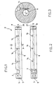
- an extruder for temperature-controlled extrusion comprising an extrusion chamber which forms a cylindrical bore with a feed aperture and a discharge aperture, the said cylindrical bore being developed about an axis of symmetry and interacting with means of conveying and processing the material to be extruded, in which the said extrusion chamber has at least one measurement cavity for housing at least one heat sensor, characterized in that the said measurement cavity extends in a direction contained in a plane tangent to a cylinder having the said axis of symmetry and a diameter greater than the diameter of the said cylindrical bore.
- an extrusion machine indicated as a whole by the number 1, comprises a base 2, an extrusion chamber 3, drive means 4 and a transmission mechanism 5.
- the extrusion chamber 3 is of elongate and essentially prismatic shape, with a cylindrical bore 6 extending through the whole length of the said extrusion chamber 3.
- the cylindrical bore 6 is developed about an axis of symmetry s, which also forms the longitudinal axis of the extrusion chamber 3.
- the extrusion chamber 3 has a transverse feed aperture 7, which is in communication with the said cylindrical bore 6.
- the cylindrical bore 6 opens to the outside at both ends of the extrusion chamber 3, forming a discharge aperture 8 and a drive aperture 9.
- conveying and processing means for the material to be extruded.
- the said conveying and processing means comprise a screw 10 with a variable core diameter and a variable pitch and inclination of the thread.
- the extrusion chamber 3 is divided longitudinally into a plurality of temperature zones, for example the temperature zones 11a, 11b and 11c.
- Heating and/or cooling devices 12 for example electrical resistors and coolant tubing, are positioned on the outer surface of the said extrusion chamber 3.
- the said heating and/or cooling devices are referred to below as temperature regulators 12.
- the extrusion chamber 3, together with the said temperature regulators 12, is wrapped in a layer of thermal insulation material 13.
- the shell of the extrusion chamber 3 has holes 14 which extend in a tangential direction with respect to the aforesaid cylindrical bore 6.
- These holes 14, referred to below as measurement cavities 14, house corresponding temperature sensors 15, which are also orientated in a tangential direction with respect to the cylindrical bore 6.
- the radial distance of the said measurement cavities 14 from the cylindrical bore 6 is less than half the wall thickness of the said extrusion chamber 3, and the radial distance of the said measurement cavities 14 from the cylindrical bore 6 is preferably less than a third of the wall thickness of the said extrusion chamber 3.
- the said radial distance between the measurement cavities 14 and the cylindrical bore 6 is equal to half the diameter of the corresponding heat sensor 15.
- the heat sensors 15 are in communication with a control unit 24 by data transmission means 23, and the control unit 24, in turn, is connected to the aforesaid temperature regulators 12 by data transmission means 23.
- the driving motor 4 in Figure 5 is an electric motor whose rotor is connected to the aforesaid transmission mechanism 5.
- the transmission mechanism 5 comprises reduction means 16 and a transmission shaft 17.
- the said transmission shaft 17 is orientated in the longitudinal direction of the extrusion chamber 3 and connected to the screw 10 through the drive aperture 9.
- the assembly consisting of the driving motor 4, the transmission mechanism 5 and the extrusion chamber 3 is fixed on a carriage chassis 18.
- the said carriage chassis 18 rests with rollers 19 on guide rails 20, provided on the base 2 of the extrusion machine 1.
- An extrusion die 21 is placed at the discharge aperture 8 of the extrusion chamber 3.
- the rotational movement of the rotor of the driving motor 4 is converted by the reduction means 16 to a rotational movement of the transmission shaft 17 with the necessary angular velocity and torque for the extrusion process.
- the transmission shaft 17, being coupled to the shank of the screw 10, transmits the said rotational movement to the screw.
- Raw material 22, introduced into the cylindrical bore 6 through the feed aperture 7, is conveyed towards the discharge aperture 8 of the extrusion chamber 3.
- the variation of the core diameter of the screw 10 causes a variation of the space available for the raw material 22 in the corresponding area within the cylindrical bore 6.
- the inclination and the pitch length of the thread of the screw 10 determine the flow rate of the material and the intensity of mixing.
- the temperature regulators 12, located on the outer surface of the extrusion chamber 3, can be used to heat and cool the shell of the extrusion chamber 3, which in turn transmits the heat to the raw material 22 within the cylindrical bore 6.
- the thermal insulation layer 13 reduces the losses of thermal energy due to natural convection and thermal radiation from the outer surface of the extrusion chamber 3 and from the temperature regulators 12 themselves.
- the said layer of thermal insulation material 13 makes the extrusion process less sensitive to external thermal and climatic conditions.
- the temperature of the material within the cylindrical bore 6 depends on many factors, which are difficult to control. Any heat treatment to be applied during the extrusion process therefore requires a system of temperature measurement and regulation.
- the measurement cavities 14, formed in the shell of the extrusion chamber 3, house the heat sensors 15.
- the said heat sensors 15, being orientated tangentially with respect to the cylindrical bore 6, are orientated essentially perpendicularly with respect to the direction of the maximum temperature gradient.
- the heat sensors 15 are therefore positioned along an isothermal line, determined solely by the radial distance between the corresponding measurement cavity 14 and the longitudinal axis s.
- the tangential positioning of the measurement cavities 14 with respect to the cylindrical bore 6 also enables the thermal probe to be inserted very deeply into the shell of the extrusion chamber 3, thus removing it from any external effects.
- the heat sensors 15 measure the temperature and the change of temperature as a function of the position in the extrusion chamber 3 and as a function of time, and transmit the corresponding data via transmission means 23 to a control unit 24 which processes the received data and, in turn, operates the temperature regulators 12, thus providing temperature control with feedback from the said sensors 15.
- the raw material 22 is conveyed to the discharge aperture 8 where an extrusion die forms the extruded or melted material into sheets, tubes, bars or any other shape suitable for profile forming.
- the extruder 1 for temperature-controlled extrusion according to the invention has numerous advantages.
- any error of positioning of the heat sensors 15 only causes a negligible error in the radial distance between the sensitive point of the thermal probe 15 and the cylindrical bore 6. This provides unusually reliable and precise measurement of the temperature.
- the positioning of the measurement cavities 14 according to the invention also enables the thermal probe 15 to be inserted very deeply into the shell of the extrusion chamber 3, thus providing exceptional protection from any external effects on the measurement of the temperature. This also has a favourable effect in situations in which the thermal insulation 13 is temporarily removed for the maintenance of the temperature regulators, for example in the case of any replacement during the operation of the extruder 1.
- the position of the measurement cavities 14 according to the invention also enables the heat sensors to be brought closer to raw material 22 than in the prior art, without weakening the extrusion chamber 3.
- the quality of temperature measurement and regulation is therefore independent of the diameter of the extrusion chamber 2.
- the aforesaid characteristics considerably increase the reliability and repeatability of measurement, and therefore of the extrusion process, in case of comparison or replacement with other heat sensors 15 of the same type.
- the response times of the heat sensors 15 and also of the temperature regulators 12 become shorter, thus providing a considerable improvement in the temperature regulation performance of the extrusion machine 1.
- one or more measurement cavities 14 in a direction which is essentially parallel to the cylindrical bore 6, one or more heat sensors 15 being inserted in the said measurement cavities.
- One embodiment of the invention has a single measurement cavity 14 which extends in a parallel way along the whole cylindrical bore 6 and can comprise a succession of heat sensors 15 or continuous temperature measurement means, as shown for example in Figure 6.
- the present invention of an extruder for temperature-controlled extrusion is not limited to the extrusion of plastic material, but can be applied to any linear temperature-controlled process, which may be repetitive, in which direct access of the sensor means to the process space is prevented, for example in the extrusion, processing and packaging of food products, the extrusion of synthetic, composite, metallic and other materials.
- the functions of the driving motor 4, the transmission mechanism 5, and the screw 10 are carried out by a pump which conveys and compresses the raw material 22 during the extrusion process.
Landscapes
- Engineering & Computer Science (AREA)
- Mechanical Engineering (AREA)
- Physics & Mathematics (AREA)
- Thermal Sciences (AREA)
- Extrusion Moulding Of Plastics Or The Like (AREA)
Applications Claiming Priority (2)
| Application Number | Priority Date | Filing Date | Title |
|---|---|---|---|
| IT0100234 | 2001-05-15 | ||
| WOPCT/IT01/00234 | 2001-05-15 |
Publications (2)
| Publication Number | Publication Date |
|---|---|
| EP1258335A1 true EP1258335A1 (de) | 2002-11-20 |
| EP1258335B1 EP1258335B1 (de) | 2005-10-26 |
Family
ID=11133657
Family Applications (1)
| Application Number | Title | Priority Date | Filing Date |
|---|---|---|---|
| EP01203378A Expired - Lifetime EP1258335B1 (de) | 2001-05-15 | 2001-09-07 | Extrudiervorrichtung für temperaturkontrollierte Extrusion |
Country Status (3)
| Country | Link |
|---|---|
| EP (1) | EP1258335B1 (de) |
| AT (1) | ATE307713T1 (de) |
| DE (1) | DE60114373T2 (de) |
Citations (3)
| Publication number | Priority date | Publication date | Assignee | Title |
|---|---|---|---|---|
| GB2107639A (en) * | 1981-10-22 | 1983-05-05 | Cincinnati Milacron Inc | Temperature control of intersecting screen extruder barrel |
| US4480981A (en) * | 1982-02-27 | 1984-11-06 | Fujikura Ltd. | System for controlling temperature of molten resin in cylinder of extruder |
| US5324108A (en) * | 1990-04-02 | 1994-06-28 | Kleinewefers Kunststoffanlagen Gmbh | Arrangement for pin cylinder extruders |
-
2001
- 2001-09-07 DE DE60114373T patent/DE60114373T2/de not_active Expired - Lifetime
- 2001-09-07 AT AT01203378T patent/ATE307713T1/de not_active IP Right Cessation
- 2001-09-07 EP EP01203378A patent/EP1258335B1/de not_active Expired - Lifetime
Patent Citations (3)
| Publication number | Priority date | Publication date | Assignee | Title |
|---|---|---|---|---|
| GB2107639A (en) * | 1981-10-22 | 1983-05-05 | Cincinnati Milacron Inc | Temperature control of intersecting screen extruder barrel |
| US4480981A (en) * | 1982-02-27 | 1984-11-06 | Fujikura Ltd. | System for controlling temperature of molten resin in cylinder of extruder |
| US5324108A (en) * | 1990-04-02 | 1994-06-28 | Kleinewefers Kunststoffanlagen Gmbh | Arrangement for pin cylinder extruders |
Also Published As
| Publication number | Publication date |
|---|---|
| EP1258335B1 (de) | 2005-10-26 |
| DE60114373D1 (de) | 2005-12-01 |
| ATE307713T1 (de) | 2005-11-15 |
| DE60114373T2 (de) | 2006-08-10 |
Similar Documents
| Publication | Publication Date | Title |
|---|---|---|
| US10684603B2 (en) | Dynamically controlled screw-driven extrusion | |
| US5820900A (en) | Heating device for an injection mold apparatus | |
| EP3625025B1 (de) | Anpassbarer hochleistungsextrusionskopf für systeme zur herstellung kondensierter filamente | |
| EP0287551B1 (de) | Verfahren zur Dickenregelung eines extrudierten Kunststoffgegenstandes | |
| Tadmor et al. | Solids conveying in screw extruders part II: Non isothermal model | |
| US5909958A (en) | Screw extruder with independently adjustable groove depth | |
| US20210053293A1 (en) | High speed extrusion 3-d printing system | |
| EP0089130A1 (de) | Vorrichtung zur Temperaturregelung von geschmolzenem Harz im Extruderzylinder | |
| WO2002036326A1 (en) | Method and apparatus for controlling a mold melt-flow process using temperature sensors | |
| US5064586A (en) | Ceramic material extruding method and apparatus therefor | |
| US10807292B2 (en) | Extrusion die and nozzle cooling system for large scale 3D additive manufacturing | |
| US20210078230A1 (en) | Plasticizing cylinder of a plastic extruder or an injection molding machine | |
| US4309114A (en) | Method for attaining maximum production effectiveness in a plasticating extruder | |
| EP1258335B1 (de) | Extrudiervorrichtung für temperaturkontrollierte Extrusion | |
| NL7811121A (nl) | Werkwijze ter vervaardiging van kunststofbuizen, als- mede inrichting voor het uitvoeren van de werkwijze. | |
| CN108327252A (zh) | 螺杆式挤出系统及包含该系统的3d打印机 | |
| EP3663073A1 (de) | 3d-druck-kopfsystem mit kombinierten verarbeitungsabschnitten und einem integral angeformten verarbeitungskanal für die generative fertigung | |
| EP0242340A2 (de) | Wärmeaustauscher, bestehend aus modularen Elementen, insbesondere für Extruderzylinder, Spritzgiessmaschinen, Ziehmaschinen und dergleichen Kunststoffverarbeitungsmaschinen | |
| US11931958B2 (en) | Extrusion nozzle for additive manufacturing | |
| EP2017062B1 (de) | Schraubengehäuse für einen Doppelschneckenextruder, der Doppelschneckenextruder und das Verfahren zur Herstellung eines Schraubengehäuses | |
| CN107073538A (zh) | 挤压机挤压筒和用于挤压机挤压筒的外套及方法 | |
| EP4673267A1 (de) | Schneckenextruder und verfahren zur steuerung des extrusionsdrucks in einem schneckenextruder | |
| WO2012099824A2 (en) | Electric heater crushable cores and compacted unitary heater device, and method of making such devices | |
| Schöppner et al. | Investigation of the barrel temperature profile on the process behavior of single screw extruders and strategies to determine the optimal temperature control | |
| Kausadikar et al. | Design and Analysis of Single Screw Extruder for Hybrid Manufacturing |
Legal Events
| Date | Code | Title | Description |
|---|---|---|---|
| PUAI | Public reference made under article 153(3) epc to a published international application that has entered the european phase |
Free format text: ORIGINAL CODE: 0009012 |
|
| AK | Designated contracting states |
Kind code of ref document: A1 Designated state(s): AT BE CH CY DE DK ES FI FR GB GR IE IT LI LU MC NL PT SE TR |
|
| AX | Request for extension of the european patent |
Free format text: AL;LT;LV;MK;RO;SI |
|
| 17P | Request for examination filed |
Effective date: 20021112 |
|
| AKX | Designation fees paid |
Designated state(s): AT BE CH CY DE DK ES FI FR GB GR IE IT LI LU MC NL PT SE TR |
|
| 17Q | First examination report despatched |
Effective date: 20040302 |
|
| GRAP | Despatch of communication of intention to grant a patent |
Free format text: ORIGINAL CODE: EPIDOSNIGR1 |
|
| GRAS | Grant fee paid |
Free format text: ORIGINAL CODE: EPIDOSNIGR3 |
|
| RAP1 | Party data changed (applicant data changed or rights of an application transferred) |
Owner name: ITALCOPPIE S.R.L. |
|
| GRAA | (expected) grant |
Free format text: ORIGINAL CODE: 0009210 |
|
| AK | Designated contracting states |
Kind code of ref document: B1 Designated state(s): AT BE CH CY DE DK ES FI FR GB GR IE IT LI LU MC NL PT SE TR |
|
| PG25 | Lapsed in a contracting state [announced via postgrant information from national office to epo] |
Ref country code: FI Free format text: LAPSE BECAUSE OF FAILURE TO SUBMIT A TRANSLATION OF THE DESCRIPTION OR TO PAY THE FEE WITHIN THE PRESCRIBED TIME-LIMIT Effective date: 20051026 Ref country code: NL Free format text: LAPSE BECAUSE OF FAILURE TO SUBMIT A TRANSLATION OF THE DESCRIPTION OR TO PAY THE FEE WITHIN THE PRESCRIBED TIME-LIMIT Effective date: 20051026 Ref country code: AT Free format text: LAPSE BECAUSE OF FAILURE TO SUBMIT A TRANSLATION OF THE DESCRIPTION OR TO PAY THE FEE WITHIN THE PRESCRIBED TIME-LIMIT Effective date: 20051026 Ref country code: LI Free format text: LAPSE BECAUSE OF FAILURE TO SUBMIT A TRANSLATION OF THE DESCRIPTION OR TO PAY THE FEE WITHIN THE PRESCRIBED TIME-LIMIT Effective date: 20051026 Ref country code: CH Free format text: LAPSE BECAUSE OF FAILURE TO SUBMIT A TRANSLATION OF THE DESCRIPTION OR TO PAY THE FEE WITHIN THE PRESCRIBED TIME-LIMIT Effective date: 20051026 Ref country code: BE Free format text: LAPSE BECAUSE OF FAILURE TO SUBMIT A TRANSLATION OF THE DESCRIPTION OR TO PAY THE FEE WITHIN THE PRESCRIBED TIME-LIMIT Effective date: 20051026 |
|
| REG | Reference to a national code |
Ref country code: GB Ref legal event code: FG4D |
|
| REG | Reference to a national code |
Ref country code: CH Ref legal event code: EP |
|
| REG | Reference to a national code |
Ref country code: IE Ref legal event code: FG4D |
|
| REF | Corresponds to: |
Ref document number: 60114373 Country of ref document: DE Date of ref document: 20051201 Kind code of ref document: P |
|
| PG25 | Lapsed in a contracting state [announced via postgrant information from national office to epo] |
Ref country code: SE Free format text: LAPSE BECAUSE OF FAILURE TO SUBMIT A TRANSLATION OF THE DESCRIPTION OR TO PAY THE FEE WITHIN THE PRESCRIBED TIME-LIMIT Effective date: 20060126 Ref country code: GR Free format text: LAPSE BECAUSE OF FAILURE TO SUBMIT A TRANSLATION OF THE DESCRIPTION OR TO PAY THE FEE WITHIN THE PRESCRIBED TIME-LIMIT Effective date: 20060126 Ref country code: DK Free format text: LAPSE BECAUSE OF FAILURE TO SUBMIT A TRANSLATION OF THE DESCRIPTION OR TO PAY THE FEE WITHIN THE PRESCRIBED TIME-LIMIT Effective date: 20060126 |
|
| PG25 | Lapsed in a contracting state [announced via postgrant information from national office to epo] |
Ref country code: ES Free format text: LAPSE BECAUSE OF FAILURE TO SUBMIT A TRANSLATION OF THE DESCRIPTION OR TO PAY THE FEE WITHIN THE PRESCRIBED TIME-LIMIT Effective date: 20060206 |
|
| PG25 | Lapsed in a contracting state [announced via postgrant information from national office to epo] |
Ref country code: PT Free format text: LAPSE BECAUSE OF FAILURE TO SUBMIT A TRANSLATION OF THE DESCRIPTION OR TO PAY THE FEE WITHIN THE PRESCRIBED TIME-LIMIT Effective date: 20060327 |
|
| NLV1 | Nl: lapsed or annulled due to failure to fulfill the requirements of art. 29p and 29m of the patents act | ||
| REG | Reference to a national code |
Ref country code: CH Ref legal event code: PL |
|
| ET | Fr: translation filed | ||
| PLBE | No opposition filed within time limit |
Free format text: ORIGINAL CODE: 0009261 |
|
| STAA | Information on the status of an ep patent application or granted ep patent |
Free format text: STATUS: NO OPPOSITION FILED WITHIN TIME LIMIT |
|
| PG25 | Lapsed in a contracting state [announced via postgrant information from national office to epo] |
Ref country code: IE Free format text: LAPSE BECAUSE OF NON-PAYMENT OF DUE FEES Effective date: 20060907 |
|
| PG25 | Lapsed in a contracting state [announced via postgrant information from national office to epo] |
Ref country code: MC Free format text: LAPSE BECAUSE OF NON-PAYMENT OF DUE FEES Effective date: 20060930 |
|
| 26N | No opposition filed |
Effective date: 20060727 |
|
| REG | Reference to a national code |
Ref country code: IE Ref legal event code: MM4A |
|
| PG25 | Lapsed in a contracting state [announced via postgrant information from national office to epo] |
Ref country code: TR Free format text: LAPSE BECAUSE OF FAILURE TO SUBMIT A TRANSLATION OF THE DESCRIPTION OR TO PAY THE FEE WITHIN THE PRESCRIBED TIME-LIMIT Effective date: 20051026 Ref country code: LU Free format text: LAPSE BECAUSE OF NON-PAYMENT OF DUE FEES Effective date: 20060907 |
|
| PG25 | Lapsed in a contracting state [announced via postgrant information from national office to epo] |
Ref country code: CY Free format text: LAPSE BECAUSE OF FAILURE TO SUBMIT A TRANSLATION OF THE DESCRIPTION OR TO PAY THE FEE WITHIN THE PRESCRIBED TIME-LIMIT Effective date: 20051026 |
|
| PGFP | Annual fee paid to national office [announced via postgrant information from national office to epo] |
Ref country code: GB Payment date: 20120920 Year of fee payment: 12 |
|
| PGFP | Annual fee paid to national office [announced via postgrant information from national office to epo] |
Ref country code: IT Payment date: 20120716 Year of fee payment: 12 |
|
| PGFP | Annual fee paid to national office [announced via postgrant information from national office to epo] |
Ref country code: FR Payment date: 20121012 Year of fee payment: 12 Ref country code: DE Payment date: 20121130 Year of fee payment: 12 |
|
| GBPC | Gb: european patent ceased through non-payment of renewal fee |
Effective date: 20130907 |
|
| REG | Reference to a national code |
Ref country code: DE Ref legal event code: R119 Ref document number: 60114373 Country of ref document: DE Effective date: 20140401 |
|
| REG | Reference to a national code |
Ref country code: FR Ref legal event code: ST Effective date: 20140530 |
|
| PG25 | Lapsed in a contracting state [announced via postgrant information from national office to epo] |
Ref country code: GB Free format text: LAPSE BECAUSE OF NON-PAYMENT OF DUE FEES Effective date: 20130907 |
|
| PG25 | Lapsed in a contracting state [announced via postgrant information from national office to epo] |
Ref country code: DE Free format text: LAPSE BECAUSE OF NON-PAYMENT OF DUE FEES Effective date: 20140401 Ref country code: FR Free format text: LAPSE BECAUSE OF NON-PAYMENT OF DUE FEES Effective date: 20130930 Ref country code: IT Free format text: LAPSE BECAUSE OF NON-PAYMENT OF DUE FEES Effective date: 20130907 |