EP1258407A2 - Procédé et dispositif pour déterminer un décalage corrigé - Google Patents
Procédé et dispositif pour déterminer un décalage corrigé Download PDFInfo
- Publication number
- EP1258407A2 EP1258407A2 EP02008629A EP02008629A EP1258407A2 EP 1258407 A2 EP1258407 A2 EP 1258407A2 EP 02008629 A EP02008629 A EP 02008629A EP 02008629 A EP02008629 A EP 02008629A EP 1258407 A2 EP1258407 A2 EP 1258407A2
- Authority
- EP
- European Patent Office
- Prior art keywords
- offset value
- vehicle
- determined
- offset
- sensor
- Prior art date
- Legal status (The legal status is an assumption and is not a legal conclusion. Google has not performed a legal analysis and makes no representation as to the accuracy of the status listed.)
- Granted
Links
Images



Classifications
-
- B—PERFORMING OPERATIONS; TRANSPORTING
- B60—VEHICLES IN GENERAL
- B60T—VEHICLE BRAKE CONTROL SYSTEMS OR PARTS THEREOF; BRAKE CONTROL SYSTEMS OR PARTS THEREOF, IN GENERAL; ARRANGEMENT OF BRAKING ELEMENTS ON VEHICLES IN GENERAL; PORTABLE DEVICES FOR PREVENTING UNWANTED MOVEMENT OF VEHICLES; VEHICLE MODIFICATIONS TO FACILITATE COOLING OF BRAKES
- B60T8/00—Arrangements for adjusting wheel-braking force to meet varying vehicular or ground-surface conditions, e.g. limiting or varying distribution of braking force
- B60T8/32—Arrangements for adjusting wheel-braking force to meet varying vehicular or ground-surface conditions, e.g. limiting or varying distribution of braking force responsive to a speed condition, e.g. acceleration or deceleration
- B60T8/88—Arrangements for adjusting wheel-braking force to meet varying vehicular or ground-surface conditions, e.g. limiting or varying distribution of braking force responsive to a speed condition, e.g. acceleration or deceleration with failure responsive means, i.e. means for detecting and indicating faulty operation of the speed responsive control means
- B60T8/885—Arrangements for adjusting wheel-braking force to meet varying vehicular or ground-surface conditions, e.g. limiting or varying distribution of braking force responsive to a speed condition, e.g. acceleration or deceleration with failure responsive means, i.e. means for detecting and indicating faulty operation of the speed responsive control means using electrical circuitry
-
- B—PERFORMING OPERATIONS; TRANSPORTING
- B60—VEHICLES IN GENERAL
- B60T—VEHICLE BRAKE CONTROL SYSTEMS OR PARTS THEREOF; BRAKE CONTROL SYSTEMS OR PARTS THEREOF, IN GENERAL; ARRANGEMENT OF BRAKING ELEMENTS ON VEHICLES IN GENERAL; PORTABLE DEVICES FOR PREVENTING UNWANTED MOVEMENT OF VEHICLES; VEHICLE MODIFICATIONS TO FACILITATE COOLING OF BRAKES
- B60T2250/00—Monitoring, detecting, estimating vehicle conditions
- B60T2250/06—Sensor zero-point adjustment; Offset compensation
-
- B—PERFORMING OPERATIONS; TRANSPORTING
- B60—VEHICLES IN GENERAL
- B60T—VEHICLE BRAKE CONTROL SYSTEMS OR PARTS THEREOF; BRAKE CONTROL SYSTEMS OR PARTS THEREOF, IN GENERAL; ARRANGEMENT OF BRAKING ELEMENTS ON VEHICLES IN GENERAL; PORTABLE DEVICES FOR PREVENTING UNWANTED MOVEMENT OF VEHICLES; VEHICLE MODIFICATIONS TO FACILITATE COOLING OF BRAKES
- B60T2270/00—Further aspects of brake control systems not otherwise provided for
- B60T2270/40—Failsafe aspects of brake control systems
- B60T2270/411—Offset failure
Definitions
- the invention relates to a device or a method to determine a corrected offset value.
- ACC Adaptive Cruise Control
- ACC Adaptive Cruise Control
- DE 196 36 443 A1 describes a system for monitoring Known sensors in a vehicle.
- This system contains Means with which at least for two sensors, starting out of at least the signals you generated, for which Sensors of the same definition are determined.
- the system also contains other means with which in Dependence on the at least determined comparison values, a reference quantity is determined. Starting from at least the determined reference quantity is in monitoring means monitoring is carried out for at least one sensor.
- the system also contains Means with which at least one sensor Correction of the signal generated by it, at least depending on it from the reference size.
- the advantage of the invention over the above State of the art is that with the invention Device or the inventive method by the second means a more precise determination of the offset values, which determine the output signals of the vehicle sensor, he follows.
- This more precise determination of the offset values takes place in that by the first means at least two the Offset of the sensor representing offset values to at least two different types can be identified.
- By the inclusion of at least one error band becomes one even higher precision in determining the corrected Offset value reached.
- the specification of the minimum and maximum values enables that the determination of the corrected offset value of the Vehicle sensor by averaging between the Minimum of all maximum values and the maximum of all minimum values those obtained in at least two different ways Minimum values and maximum values of the offset values of the vehicle sensor he follows.
- This method of determining the corrected Offset value is characterized by the fact that in the Control unit is particularly easy to implement.
- a further advantageous embodiment is characterized in that that the determination of the corrected offset value of the vehicle sensor by weighted averaging between the determined offset values of the vehicle sensor takes place, the offset value with increasing Width of the error band a lower weight in the averaging receives.
- a wide range of errors means that the specification of the offset value with a greater uncertainty connected is. Therefore "unsafe" offset values go with you less weight than “safe” offset values in the determination the corrected offset value.
- the vehicle sensor detects the yaw movement of the vehicle.
- the present invention can be advantageous to the output signals of a rotation rate sensor apply, i.e. the vehicle sensor detects the yaw rate.
- the invention can be advantageous in one system used for automatic distance control and / or control become.
- the second Corrected offset value determined at regular intervals or not at regular intervals.
- An advantageous embodiment of the invention can, for example using four methods, namely one Standstill adjustment procedure, a steering angle procedure, a histogram method and a regression method consist.
- Fig. 1 are a vehicle control system in a schematic manner 16 and the essential for the invention Input and output channels shown.
- input signals of the Vehicle control system 16 are on the input channels the output signals of a vehicle sensor 10 and others Signals from unspecified input data sources 11 available.
- the output signals of the vehicle control system 16 go to the m further control units 15a, ... 15m.
- FIG. 2 shows a special version of the present invention for the case of an adaptive cruise control (ACC) system.
- ACC adaptive cruise control
- the radar sensors are not shown, for example.
- the vehicle sensor 10 is designed as a rotation rate sensor 21b.
- the further input sources 11 are designed as steering wheel angle sensors 21a and as wheel speed sensors 21c.
- the rotation rate sensor 21b provides an output signal ⁇ which represents the yaw rate
- the steering wheel angle sensor 21a provides an output signal ⁇ which represents the steering wheel angle
- the wheel speed sensors 21c provide output signals n i which represent the wheel speeds of the individual wheels.
- These output signals ⁇ , ⁇ and n i and the signal v representing the longitudinal vehicle speed are input to the vehicle control system 16.
- the longitudinal vehicle speed is generally not detected directly by a sensor, but rather is determined from the signals n i supplied by the wheel speed sensors 21c, which represent the wheel speeds of the individual wheels. This determination can take place, for example, in the control unit of a vehicle dynamics control system (ESP).
- ESP vehicle dynamics control system
- the standstill adjustment method 23a requires, as input signals, the signal v representing the longitudinal vehicle speed and the signal ⁇ representing the yaw rate.
- the steering angle method 23b also requires the signal ⁇ representing the steering wheel angle.
- the signal ⁇ representing the yaw rate and the signal v representing the longitudinal vehicle speed are required as the input signal for the histogram method 23c.
- the regression method 23d requires as inputs the signals n i representing the wheel speeds, the signal ⁇ representing the yaw rate and the signal v representing the longitudinal vehicle speed
- the standstill adjustment method 23a provides as output signals a signal ⁇ off1 , which represents an approximate value for the yaw rate offset of the rotation rate sensor 21b, and a further signal ⁇ off1 , which represents half the width of the associated error band .
- the steering angle method 23b supplies a signal ⁇ off2 , which represents an approximate value for the yaw rate offset of the rotation rate sensor 21b, and a further signal ⁇ off2 , which represents half the width of the associated error band .
- the histogram method 23c supplies a signal ⁇ off3 , which represents the yaw rate offset of the rotation rate sensor 21b, and a further signal ⁇ off3 , which represents half the width of the associated error band .
- the regression method 23d supplies a signal ⁇ off4 , which represents the yaw rate offset of the yaw rate sensor 21b, and a further signal ⁇ off4 , which represents half the width of the associated error band .
- the error band is a measure of the maximum absolute error, with which the offset of the output signal of the rotation rate sensor 21b representative size is afflicted.
- a corrected offset value ⁇ offcorr of the yaw rate sensor which is compared with the quantities ⁇ off1,. .., ⁇ off4 is characterized by increased accuracy.
- the four methods used namely the standstill adjustment method, the steering angle method, the histogram method and the regression method different areas of validity, depending from the driving condition. That means depending on Driving condition, possibly not all four methods used at the same time the quantities representing the offset value determine. For those processes that currently do not determine the values representing the offset value, the last valid, determined with this procedure, the Size representing offset value taken. At the same time the error band determined for this size was expanded in time. That means that the associated error band all the more the longer the last valid determination of this becomes wider size representing the offset value.
- This Recourse to the last determined offset value is required for each procedure a storage of at least the last one determined offset value and the last determined Margin of error.
- FIG. 3 This widening of the error band is shown in FIG. 3 in a qualitative manner.
- the time t is plotted along the abscissa, the values ⁇ offi , ⁇ offmini and ⁇ offmaxi are plotted in the ordinate direction .
- ⁇ offi denotes the yaw rate sensor offset value determined by the i-th method.
- ⁇ offmini is the minimum value defined by the error band
- ie ⁇ offmini ⁇ offi - ⁇ offi
- ⁇ offmaxi is the minimum value defined by the error band
- ie ⁇ offmaxi ⁇ offi + ⁇ offi .
- the determined corrected offset value ⁇ offkorr is fed to a further block 12, in which further functions of the vehicle control system are implemented.
- block 12 also has the variable ⁇ offcorr as an input signal.
- blocks 23a, 23b, 23c and 23d are discussed in more detail, which deliver the quantities ⁇ off1 , ..., ⁇ off4 representing the offset of the output signal of the rotation rate sensor 21b.
- the standstill adjustment method 23a provides the variables ⁇ off1 , which represent the offset of the output signal of the rotation rate sensor 21b, regardless of the current state of motion of the vehicle, in particular also in the case of a non-stationary vehicle.
- the very small wheel speeds n i then present can no longer be detected by the wheel speed sensors and are incorrectly recognized as zero.
- a device in the vehicle for determining the longitudinal vehicle speed is incorrectly determined to be vanishing.
- the limit speed v G is the longitudinal speed of the vehicle which has just been recognized as not vanishing.
- the longitudinal speed zero is incorrectly determined for each longitudinal speed lower than the limit speed v G.
- Points b) and c) ensure that a Vehicle with a vanishing longitudinal speed stands on a rotating plate, not recorded as stationary becomes.
- the output signal ⁇ of the rotation rate sensor 21b is read into block 23a at regular discrete sampling times t i with constant time intervals ⁇ t a .
- a time interval T n n ⁇ ⁇ t a is determined, where n is an integer greater than 2. If the conditions a), b) and c) defining the standstill are met during a time interval T n at all sampling times t i falling in this interval, the standstill case is considered to be given.
- Such a time interval T n in which the conditions a), b) and c) defining the standstill are all fulfilled at the same time at every sampling time falling in this interval, is referred to below as the fulfillment interval.
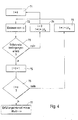
- the process sequence for the detection of a fulfillment interval is shown in FIG. 4.
- the output signal ⁇ of the yaw rate sensor is then read in in block 72.
- it is checked whether all three standstill conditions a), b) and c) are fulfilled at the same time. If this is the case, then the number i is incremented by 1 in block 75. If this is not the case, then i 0 is set in block 74 and, at the same time, block 71 is started again at a later point in time t a .
- the variable i indicates the number of uninterrupted fulfillments of all three conditions a), b) and c) defining the standstill.
- the variable "value" is assigned the most current value ⁇ of the output signal of the yaw rate sensor. In the exemplary embodiment, this is a filtered value. If the number i has not yet reached the value n in block 76, then the output signal of the yaw rate sensor ⁇ is read in again at block 72 at a later point in time (block 78).
- the last sampled signal ⁇ of the penultimate fulfillment interval is used in each case to determine the offset value ⁇ off1 in block 23a.
- a filtered or averaged or both filtered and averaged signal can also be used.
- condition a) is not met.
- the vehicle is not at a standstill.
- phase 3 all three conditions are met, so the case of a standstill is assumed, although the vehicle was still coasting. In order to avoid further processing of the first signals ⁇ determined there as signals representing vehicle standstill, the time interval T n was introduced.
- the length of the time interval T n is determined by the necessary consideration of the coasting during braking processes below the limit speed v G defined in a) and the necessary consideration of filter run times of the signal ⁇ in block 23a. Ideally, the length of the time interval T n is longer than an assumed realistic duration of phase 3 and the filter runtimes. In phase 4, all 3 conditions a), b) and c) are met at all sampling times t i .
- the output signal of the rotation rate sensor 21b is now read into block 23a over shorter time intervals T m , and the yaw rate offset ⁇ off1 from the penultimate maintenance interval is determined therefrom.
- phase 5 too, all 3 conditions a), b) and c) are met at all sampling times, even though the vehicle is no longer at a standstill.
- the yaw rate offset ⁇ off1 is determined from the penultimate compliance interval , which ideally still falls into phase 4, in which a vehicle that was actually stationary was still present.
- phase 6 the 3 conditions a), b) and c) are no longer fulfilled at the same time, which is why the vehicle is assumed to be no longer at a standstill and no further offset values ⁇ off1 are determined. Since the vehicle is now in motion, no further offset values ⁇ off1 can be determined until a new vehicle standstill , characterized by the fulfillment of all three conditions a), b) and c), occurs.
- the standstill adjustment method also works when the vehicle is not detected as standing still.
- the last valid offset value ⁇ off1 determined is read from a memory and used further.
- the error band with half the width ⁇ off1 is now widened in time. This clearly means that the wider the error band, the more time has passed since the last valid determination of the offset value ⁇ off1 .
- the steering angle method In contrast to the standstill adjustment method, the steering angle method only works when the vehicle is not stationary.
- the steering ratio i L a characteristic vehicle speed v ch and the wheelbase 1 are included in this relationship.
- the steering ratio is the mechanical ratio between the steering wheel angle ⁇ and the steering angle of the front wheels.
- the offset ⁇ off2 is the difference between the yaw rate ⁇ LWS calculated from the above relationship (1) and the yaw rate ⁇ measured by the yaw rate sensor.
- relationship (1) In addition to the calculation of an offset value ⁇ off2 , relationship (1) also allows the width of an error band to be calculated using the error propagation law.
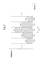
- the yaw rate value ⁇ k therefore includes the interval with the lower limit ⁇ k - ⁇ / 2 and the upper limit ⁇ k + ⁇ / 2. These intervals are referred to below as classes.
- the error band can, for example, be determined as the narrower become, the more pronounced the maximum of the histogram is.
- the histogram method it is advisable to consider only yaw rate values up to a maximum amount that can be specified. Furthermore, offset values should only be determined from the histogram method if the longitudinal vehicle speed exceeds a variable to be specified. If these conditions are not met, the last valid offset value determined is used for the histogram method, the associated error band widening with increasing time interval. Since the histogram method is a statistical method, it requires a sufficiently large number of measured values. The histogram values of the last ignition cycle are therefore read in as initialization values when the vehicle is started.
- the individual classes can be filled in the histogram, for example, by simply adding up the number of yaw rate values to be assigned to the individual classes. In the exemplary embodiment, however, the individual classes are not filled in the histogram by simply adding up the number of yaw rate values to be assigned to the individual classes, but rather by low-pass filtering with exponential characteristics.
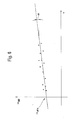
- FIG. 6 shows qualitatively an xy diagram obtained with the regression method.
- the longitudinal vehicle speed v is plotted on the x-axis and a variable ⁇ diff on the y-axis.
- v l and v r are the actual wheel speeds on the left and right wheels of the non-driven axle
- r is the nominal value of the wheel radius
- r + ⁇ r l is the actual radius of the left wheel of the non-driven axle
- r + ⁇ r r is the actual one Radius of the right wheel of the non-driven axle
- b is the track width.
- This determination of ⁇ comp is based on the fact that different wheel speeds of the inner and outer wheels are present during cornering.
- a new point is entered into the xy diagram by measuring v and determining ⁇ diff .
- a regression line is now drawn through these points.
- the y-axis intersection point and the slope m are determined from this regression line.
- the y-axis penetration point represents the yaw rate offset ⁇ off4 and the slope m can be used to determine differences in the wheel radii of the non-driven wheels using equation (2). These differences can be due to tire tolerances. The determination of these differences can lead to the saving of a tire tolerance comparison.
- the regression method requires a speed variation. If this speed variation is too small, ie the points in the xy diagram are too crowded in the x-axis direction, the result will be inaccurate.
- the error band takes into account, for example, the variance and the mean value of the values of the longitudinal vehicle speed.
- a corrected offset value ⁇ offcorr is determined in block 24.
- the corrected offset value can be determined in different ways. For example, as shown in FIG. 7, the corrected offset value can be determined as the average of the minimum of the maximum values and the maximum of the minimum values. For this purpose, a minimum value ⁇ offi - ⁇ offi and a maximum value ⁇ offi + ⁇ offi are calculated from the offset value ⁇ offi determined by the i-th method and the associated error band with half the width ⁇ offi . Now the minimum and maximum values of all 4 methods are plotted along the ⁇ axis. The largest minimum value (identified in FIG. 7 max ( ⁇ offi - ⁇ offi )) is determined from the 4 plotted minimum values. Likewise, the smallest maximum value (identified in FIG.
- the center point of the intersection is determined and used as the corrected offset value ⁇ offcorr .
- This method can also be used if there is no common intersection, ie the largest minimum value is greater than the smallest maximum value.
- the corrected offset value can also be obtained by weighted averaging from all four determined offset values. It is advantageous here that the weight of the offset value whose error bandwidth is the smallest is the largest in the weighted averaging. This can be done, for example, using the following weighted averaging:
- the determination of the corrected offset value of the yaw rate sensor should be repeated at regular or non-regular time intervals. In practice, time intervals of the order of 0.1 seconds to 1 second prove to be advantageous.
Landscapes
- Engineering & Computer Science (AREA)
- Transportation (AREA)
- Mechanical Engineering (AREA)
- Steering Control In Accordance With Driving Conditions (AREA)
- Navigation (AREA)
- Traffic Control Systems (AREA)
- Indication And Recording Devices For Special Purposes And Tariff Metering Devices (AREA)
- Measurement Of Current Or Voltage (AREA)
Applications Claiming Priority (4)
| Application Number | Priority Date | Filing Date | Title |
|---|---|---|---|
| DE10123846 | 2001-05-16 | ||
| DE10123846 | 2001-05-16 | ||
| DE10205396 | 2002-02-09 | ||
| DE10205396A DE10205396A1 (de) | 2001-05-16 | 2002-02-09 | Verfahren und Vorrichtung zur Ermittlung eines korrigierten Offsetwertes |
Publications (3)
| Publication Number | Publication Date |
|---|---|
| EP1258407A2 true EP1258407A2 (fr) | 2002-11-20 |
| EP1258407A3 EP1258407A3 (fr) | 2003-03-19 |
| EP1258407B1 EP1258407B1 (fr) | 2008-08-20 |
Family
ID=26009310
Family Applications (1)
| Application Number | Title | Priority Date | Filing Date |
|---|---|---|---|
| EP02008629A Expired - Lifetime EP1258407B1 (fr) | 2001-05-16 | 2002-04-17 | Procédé et dispositif pour déterminer un décalage corrigé |
Country Status (3)
| Country | Link |
|---|---|
| US (1) | US6704631B2 (fr) |
| EP (1) | EP1258407B1 (fr) |
| JP (1) | JP4052874B2 (fr) |
Cited By (3)
| Publication number | Priority date | Publication date | Assignee | Title |
|---|---|---|---|---|
| EP1388473A1 (fr) * | 2002-08-05 | 2004-02-11 | Ford Global Technologies, LLC | Procédé et système de correction du décalage de capteurs |
| CN100354165C (zh) * | 2004-09-20 | 2007-12-12 | 丰田自动车株式会社 | 车辆的制动力控制装置 |
| WO2012051236A1 (fr) * | 2010-10-15 | 2012-04-19 | Robert Bosch Gmbh | Correction continue de décalage d'angle du volant de direction |
Families Citing this family (34)
| Publication number | Priority date | Publication date | Assignee | Title |
|---|---|---|---|---|
| US6834218B2 (en) * | 2001-11-05 | 2004-12-21 | Ford Global Technologies, Llc | Roll over stability control for an automotive vehicle |
| US6356188B1 (en) | 2000-09-25 | 2002-03-12 | Ford Global Technologies, Inc. | Wheel lift identification for an automotive vehicle |
| US6654674B2 (en) * | 2001-11-21 | 2003-11-25 | Ford Global Technologies, Llc | Enhanced system for yaw stability control system to include roll stability control function |
| US20040024504A1 (en) * | 2002-08-05 | 2004-02-05 | Salib Albert Chenouda | System and method for operating a rollover control system during an elevated condition |
| US20040024505A1 (en) * | 2002-08-05 | 2004-02-05 | Salib Albert Chenouda | System and method for operating a rollover control system in a transition to a rollover condition |
| US7239949B2 (en) * | 2003-02-26 | 2007-07-03 | Ford Global Technologies, Llc | Integrated sensing system |
| DE102005003292A1 (de) * | 2004-04-15 | 2005-11-03 | Continental Teves Ag & Co. Ohg | Langzeitoffsetabgleich eines Sensors |
| US7451032B2 (en) * | 2004-06-02 | 2008-11-11 | Ford Global Technologies, Llc | System and method for determining desired yaw rate and lateral velocity for use in a vehicle dynamic control system |
| US7640081B2 (en) * | 2004-10-01 | 2009-12-29 | Ford Global Technologies, Llc | Roll stability control using four-wheel drive |
| US7668645B2 (en) | 2004-10-15 | 2010-02-23 | Ford Global Technologies | System and method for dynamically determining vehicle loading and vertical loading distance for use in a vehicle dynamic control system |
| US7715965B2 (en) | 2004-10-15 | 2010-05-11 | Ford Global Technologies | System and method for qualitatively determining vehicle loading conditions |
| US7660654B2 (en) | 2004-12-13 | 2010-02-09 | Ford Global Technologies, Llc | System for dynamically determining vehicle rear/trunk loading for use in a vehicle control system |
| DE102005000657A1 (de) * | 2005-01-04 | 2006-07-13 | Robert Bosch Gmbh | Verfahren zur Offseterkennung für eine Fußgängerschutzvorrichtung |
| US7472337B2 (en) * | 2005-03-22 | 2008-12-30 | Cummins, Inc. | Method and system for detecting faults in an electronic engine control module |
| US7480547B2 (en) | 2005-04-14 | 2009-01-20 | Ford Global Technologies, Llc | Attitude sensing system for an automotive vehicle relative to the road |
| US7590481B2 (en) * | 2005-09-19 | 2009-09-15 | Ford Global Technologies, Llc | Integrated vehicle control system using dynamically determined vehicle conditions |
| US7600826B2 (en) * | 2005-11-09 | 2009-10-13 | Ford Global Technologies, Llc | System for dynamically determining axle loadings of a moving vehicle using integrated sensing system and its application in vehicle dynamics controls |
| US8121758B2 (en) * | 2005-11-09 | 2012-02-21 | Ford Global Technologies | System for determining torque and tire forces using integrated sensing system |
| DE102006032727A1 (de) * | 2006-07-14 | 2008-01-31 | Lucas Automotive Gmbh | Verfahren und Vorrichtung zur Plausibilitätskontrolle von Messwerten im Kraftfahrzeugumfeld |
| JP2008032632A (ja) * | 2006-07-31 | 2008-02-14 | Denso Corp | 角速度センサのキャリブレーション装置および角速度値特定装置 |
| JP2008070224A (ja) * | 2006-09-14 | 2008-03-27 | Denso Corp | 車載用角速度センサ |
| GB2447987B (en) * | 2007-03-30 | 2011-11-02 | P G Drives Technology Ltd | Method and apparatus for determining a value of a zero point offset of a yaw rate sensor |
| US7860676B2 (en) | 2007-06-28 | 2010-12-28 | Hillcrest Laboratories, Inc. | Real-time dynamic tracking of bias |
| US8195357B2 (en) * | 2008-04-16 | 2012-06-05 | GM Global Technology Operations LLC | In-vehicle sensor-based calibration algorithm for yaw rate sensor calibration |
| TW200951665A (en) * | 2008-06-06 | 2009-12-16 | Richtek Technology Corp | Sensing circuit and method for a flyback converter |
| JP4780168B2 (ja) * | 2008-09-29 | 2011-09-28 | 日本ビクター株式会社 | 角速度センサ補正装置および角速度センサ補正方法 |
| JP4780174B2 (ja) * | 2008-10-24 | 2011-09-28 | 日本ビクター株式会社 | 角速度センサ補正装置、角速度算出装置、角速度センサ補正方法、角速度算出方法 |
| US8165742B2 (en) * | 2008-11-14 | 2012-04-24 | Robert Bosch Gmbh | System and method for compensating sensor signals |
| US20120089297A1 (en) * | 2009-06-03 | 2012-04-12 | Toyota Jidosha Kabushiki Kaisha | Sensor offset amount estimate device |
| KR101364826B1 (ko) | 2010-11-01 | 2014-02-20 | 닌텐도가부시키가이샤 | 조작 장치 및 조작 시스템 |
| US9121866B2 (en) * | 2013-03-15 | 2015-09-01 | Autoliv Asp, Inc. | System and method for inertial sensor offset compensation |
| US9728014B2 (en) * | 2013-04-23 | 2017-08-08 | B. G. Negev Technologies And Applications Ltd. | Sensor fault detection and diagnosis for autonomous systems |
| JP6639321B2 (ja) * | 2016-04-28 | 2020-02-05 | ダイハツ工業株式会社 | 車両制御装置 |
| DE102018115428A1 (de) * | 2018-06-27 | 2020-01-02 | Valeo Schalter Und Sensoren Gmbh | Verfahren zum Ermitteln eines Offsetwertes für eine inertiale Messeinheit bei einem stationären Bewegungszustand eines Kraftfahrzeugs |
Family Cites Families (10)
| Publication number | Priority date | Publication date | Assignee | Title |
|---|---|---|---|---|
| JPH0740041B2 (ja) * | 1989-04-21 | 1995-05-01 | 日産自動車株式会社 | 横加速度センサ出力値補正装置及び四輪駆動車の駆動力配分制御装置 |
| JP3423418B2 (ja) | 1994-06-30 | 2003-07-07 | 松下電器産業株式会社 | 移動体旋回角度算出装置 |
| DE4446592B4 (de) * | 1994-12-24 | 2005-08-04 | Robert Bosch Gmbh | Fahrdynamikregelsystem |
| DE4446582B4 (de) * | 1994-12-24 | 2005-11-17 | Robert Bosch Gmbh | Fahrdynamikregelsystem |
| DE19502858C1 (de) * | 1995-01-30 | 1996-07-11 | Siemens Ag | Verfahren und Schaltungsanordnung zum Kompensieren der Signalfehler eines Giergeschwindigkeitssensors |
| FR2743162B1 (fr) * | 1995-12-27 | 1998-05-07 | Dassault Electronique | Dispositif de commande pour la securisation d'un vehicule rapide, notamment guide par un operateur embarque ou non dans ledit vehicule |
| JP3204107B2 (ja) * | 1996-08-21 | 2001-09-04 | トヨタ自動車株式会社 | ヨーレートセンサ中立点推定装置 |
| DE19636443A1 (de) * | 1996-09-07 | 1998-03-12 | Bosch Gmbh Robert | Vorrichtung und Verfahren zur Überwachung von Sensoren in einem Fahrzeug |
| DE59809199D1 (de) * | 1997-07-02 | 2003-09-11 | Bosch Gmbh Robert | Verfahren und vorrichtung zur überwachung von sensoren in einem fahrzeug |
| DE19748126A1 (de) * | 1997-07-02 | 1999-01-07 | Bosch Gmbh Robert | Verfahren und Vorrichtung zur Überwachung von Sensoren in einem Fahrzeug |
-
2002
- 2002-04-17 EP EP02008629A patent/EP1258407B1/fr not_active Expired - Lifetime
- 2002-05-16 JP JP2002141308A patent/JP4052874B2/ja not_active Expired - Fee Related
- 2002-05-16 US US10/146,781 patent/US6704631B2/en not_active Expired - Lifetime
Cited By (3)
| Publication number | Priority date | Publication date | Assignee | Title |
|---|---|---|---|---|
| EP1388473A1 (fr) * | 2002-08-05 | 2004-02-11 | Ford Global Technologies, LLC | Procédé et système de correction du décalage de capteurs |
| CN100354165C (zh) * | 2004-09-20 | 2007-12-12 | 丰田自动车株式会社 | 车辆的制动力控制装置 |
| WO2012051236A1 (fr) * | 2010-10-15 | 2012-04-19 | Robert Bosch Gmbh | Correction continue de décalage d'angle du volant de direction |
Also Published As
| Publication number | Publication date |
|---|---|
| JP4052874B2 (ja) | 2008-02-27 |
| EP1258407A3 (fr) | 2003-03-19 |
| US20030040856A1 (en) | 2003-02-27 |
| US6704631B2 (en) | 2004-03-09 |
| EP1258407B1 (fr) | 2008-08-20 |
| JP2003014478A (ja) | 2003-01-15 |
Similar Documents
| Publication | Publication Date | Title |
|---|---|---|
| EP1258407B1 (fr) | Procédé et dispositif pour déterminer un décalage corrigé | |
| EP1258708B1 (fr) | Procédé et dispositif pour la détermination des décalages à l'aide d'un histogram | |
| DE3850150T2 (de) | Gierkontrolleinrichtung für ein Fahrzeug. | |
| EP1412237B1 (fr) | Procede et dispositif pour identifier et eliminer un risque de renversement | |
| EP1826530B1 (fr) | Procédé et dispositif destinés à la détection de la dimension d'une roue | |
| DE69714806T2 (de) | Verfahren zum Ermitteln der Stellung der Lenkung eines Kraftfahrzeuges | |
| EP1157899B1 (fr) | Procédé et système de sécurité pour la détection d'un tonneau et pour le déclenchement d'un system de sécurité dans un véhicule automobile | |
| EP3687875B1 (fr) | Procédé permettant de déterminer la position du centre de gravité d'un véhicule | |
| EP2613986A1 (fr) | Détermination de l'angle de direction pour un véhicule automobile | |
| EP2005120A2 (fr) | Procédé et dispositif de détermination de la valeur absolue d'une grandeur | |
| DE102008042433A1 (de) | Verfahren und Vorrichtung zum Ermitteln eines Schwerpunktes eines Kraftfahrzeugs | |
| DE102008011607A1 (de) | Verfahren zur Anpassung der Fahrpedalcharakteristik in einem Fahrzeug | |
| EP3597452A1 (fr) | Procédé et dispositif d'estimation d'une circonférence de roue actuelle d'au moins une roue montée sur un véhicule | |
| DE102016223902A1 (de) | Verfahren und System zur Bestimmung von Radumfängen und Spurweiten eines Fahrzeugs | |
| DE10205971A1 (de) | Verfahren und Vorrichtung für die Bestimmung von Offsetwerten durch ein Histogrammverfahren | |
| EP1470978B1 (fr) | Procédé et dispositif de détection de l'état de marche | |
| DE102005047021B3 (de) | Anordnung zur Bestimmung eines absoluten Neigungswinkels gegenüber der Horizontalen | |
| DE102004059002A1 (de) | Verfahren zur Anpassung von Eingriffsparametern eines Assistenzsystems eines Fahrzeuges | |
| DE102016014325A1 (de) | Verfahren zur Anpassung eines Parkassistenzsystems an ein Fahrzeug | |
| DE10065759A1 (de) | Vorrichtung und Verfahren zur Überwachung eines Drucksensors | |
| EP1258408B1 (fr) | Procédé et dispositif pour déterminer un décalage au moyen d'un procédé de régression | |
| DE19962549C1 (de) | Verfahren und Vorrichtung zur Durchführung eines automatischen Bremsvorgangs bei Kurvenfahrt | |
| EP1070007B1 (fr) | Procede et dispositif pour determiner des valeurs de correction pour des vitesses de roue | |
| WO1999001718A1 (fr) | Procede et dispositif pour le controle de detecteurs dans un vehicule | |
| EP1240038B1 (fr) | Procede et dispositif permettant de detecter une perte de pression dans les pneus d'un vehicule a moteur |
Legal Events
| Date | Code | Title | Description |
|---|---|---|---|
| PUAI | Public reference made under article 153(3) epc to a published international application that has entered the european phase |
Free format text: ORIGINAL CODE: 0009012 |
|
| AK | Designated contracting states |
Kind code of ref document: A2 Designated state(s): AT BE CH CY DE DK ES FI FR GB GR IE IT LI LU MC NL PT SE TR |
|
| AX | Request for extension of the european patent |
Free format text: AL;LT;LV;MK;RO;SI |
|
| PUAL | Search report despatched |
Free format text: ORIGINAL CODE: 0009013 |
|
| AK | Designated contracting states |
Kind code of ref document: A3 Designated state(s): AT BE CH CY DE DK ES FI FR GB GR IE IT LI LU MC NL PT SE TR Designated state(s): AT BE CH CY DE DK ES FI FR GB GR IE IT LI LU MC NL PT SE TR |
|
| AX | Request for extension of the european patent |
Extension state: AL LT LV MK RO SI |
|
| 17P | Request for examination filed |
Effective date: 20030919 |
|
| AKX | Designation fees paid |
Designated state(s): DE FR GB IT |
|
| GRAP | Despatch of communication of intention to grant a patent |
Free format text: ORIGINAL CODE: EPIDOSNIGR1 |
|
| GRAS | Grant fee paid |
Free format text: ORIGINAL CODE: EPIDOSNIGR3 |
|
| GRAA | (expected) grant |
Free format text: ORIGINAL CODE: 0009210 |
|
| AK | Designated contracting states |
Kind code of ref document: B1 Designated state(s): DE FR GB IT |
|
| REG | Reference to a national code |
Ref country code: GB Ref legal event code: FG4D Free format text: NOT ENGLISH |
|
| REF | Corresponds to: |
Ref document number: 50212660 Country of ref document: DE Date of ref document: 20081002 Kind code of ref document: P |
|
| PLBE | No opposition filed within time limit |
Free format text: ORIGINAL CODE: 0009261 |
|
| STAA | Information on the status of an ep patent application or granted ep patent |
Free format text: STATUS: NO OPPOSITION FILED WITHIN TIME LIMIT |
|
| 26N | No opposition filed |
Effective date: 20090525 |
|
| PGFP | Annual fee paid to national office [announced via postgrant information from national office to epo] |
Ref country code: IT Payment date: 20140429 Year of fee payment: 13 |
|
| REG | Reference to a national code |
Ref country code: FR Ref legal event code: PLFP Year of fee payment: 14 |
|
| PGFP | Annual fee paid to national office [announced via postgrant information from national office to epo] |
Ref country code: GB Payment date: 20150423 Year of fee payment: 14 |
|
| PGFP | Annual fee paid to national office [announced via postgrant information from national office to epo] |
Ref country code: FR Payment date: 20150422 Year of fee payment: 14 |
|
| PG25 | Lapsed in a contracting state [announced via postgrant information from national office to epo] |
Ref country code: IT Free format text: LAPSE BECAUSE OF NON-PAYMENT OF DUE FEES Effective date: 20150417 |
|
| GBPC | Gb: european patent ceased through non-payment of renewal fee |
Effective date: 20160417 |
|
| REG | Reference to a national code |
Ref country code: FR Ref legal event code: ST Effective date: 20161230 |
|
| PG25 | Lapsed in a contracting state [announced via postgrant information from national office to epo] |
Ref country code: GB Free format text: LAPSE BECAUSE OF NON-PAYMENT OF DUE FEES Effective date: 20160417 Ref country code: FR Free format text: LAPSE BECAUSE OF NON-PAYMENT OF DUE FEES Effective date: 20160502 |
|
| PGFP | Annual fee paid to national office [announced via postgrant information from national office to epo] |
Ref country code: DE Payment date: 20200623 Year of fee payment: 19 |
|
| REG | Reference to a national code |
Ref country code: DE Ref legal event code: R119 Ref document number: 50212660 Country of ref document: DE |
|
| PG25 | Lapsed in a contracting state [announced via postgrant information from national office to epo] |
Ref country code: DE Free format text: LAPSE BECAUSE OF NON-PAYMENT OF DUE FEES Effective date: 20211103 |