EP1258439A1 - Installation pour transporter des objets sur des voies de convoyage au moyen d'un rouleau de transport mû par came - Google Patents
Installation pour transporter des objets sur des voies de convoyage au moyen d'un rouleau de transport mû par came Download PDFInfo
- Publication number
- EP1258439A1 EP1258439A1 EP02010464A EP02010464A EP1258439A1 EP 1258439 A1 EP1258439 A1 EP 1258439A1 EP 02010464 A EP02010464 A EP 02010464A EP 02010464 A EP02010464 A EP 02010464A EP 1258439 A1 EP1258439 A1 EP 1258439A1
- Authority
- EP
- European Patent Office
- Prior art keywords
- transport roller
- roller
- conveyor
- transport
- profile rail
- Prior art date
- Legal status (The legal status is an assumption and is not a legal conclusion. Google has not performed a legal analysis and makes no representation as to the accuracy of the status listed.)
- Granted
Links
- 238000009434 installation Methods 0.000 title claims 3
- 230000002093 peripheral effect Effects 0.000 claims abstract description 15
- 230000005484 gravity Effects 0.000 claims description 7
- 230000001360 synchronised effect Effects 0.000 claims description 3
- 230000000149 penetrating effect Effects 0.000 claims description 2
- 238000005096 rolling process Methods 0.000 abstract description 17
- 210000000056 organ Anatomy 0.000 abstract 3
- 230000014759 maintenance of location Effects 0.000 description 9
- 238000011161 development Methods 0.000 description 3
- 230000018109 developmental process Effects 0.000 description 3
- 238000000926 separation method Methods 0.000 description 2
- 238000010516 chain-walking reaction Methods 0.000 description 1
- 230000000694 effects Effects 0.000 description 1
- 230000006870 function Effects 0.000 description 1
- 238000007373 indentation Methods 0.000 description 1
- 230000001939 inductive effect Effects 0.000 description 1
- 238000002955 isolation Methods 0.000 description 1
- 230000000717 retained effect Effects 0.000 description 1
- 230000007704 transition Effects 0.000 description 1
- 238000011144 upstream manufacturing Methods 0.000 description 1
Images


Classifications
-
- B—PERFORMING OPERATIONS; TRANSPORTING
- B65—CONVEYING; PACKING; STORING; HANDLING THIN OR FILAMENTARY MATERIAL
- B65G—TRANSPORT OR STORAGE DEVICES, e.g. CONVEYORS FOR LOADING OR TIPPING, SHOP CONVEYOR SYSTEMS OR PNEUMATIC TUBE CONVEYORS
- B65G19/00—Conveyors comprising an impeller or a series of impellers carried by an endless traction element and arranged to move articles or materials over a supporting surface or underlying material, e.g. endless scraper conveyors
- B65G19/02—Conveyors comprising an impeller or a series of impellers carried by an endless traction element and arranged to move articles or materials over a supporting surface or underlying material, e.g. endless scraper conveyors for articles, e.g. for containers
- B65G19/025—Conveyors comprising an impeller or a series of impellers carried by an endless traction element and arranged to move articles or materials over a supporting surface or underlying material, e.g. endless scraper conveyors for articles, e.g. for containers for suspended articles
-
- B—PERFORMING OPERATIONS; TRANSPORTING
- B65—CONVEYING; PACKING; STORING; HANDLING THIN OR FILAMENTARY MATERIAL
- B65G—TRANSPORT OR STORAGE DEVICES, e.g. CONVEYORS FOR LOADING OR TIPPING, SHOP CONVEYOR SYSTEMS OR PNEUMATIC TUBE CONVEYORS
- B65G2201/00—Indexing codes relating to handling devices, e.g. conveyors, characterised by the type of product or load being conveyed or handled
- B65G2201/02—Articles
- B65G2201/0229—Clothes, clothes hangers
Definitions
- the invention relates to a system for transporting objects, especially of clothes hanging on hangers the preamble of claim 1.
- Such systems transport the objects on conveyor tracks by means of a transport roller containing two parallel to each other directed spaced front flanges and a intermediate middle part as well as one between the flanges and the central opening leading through, wherein the middle part at least one peripheral, annular Has peripheral part that is rotatable separately from both flanges is, and whereby both flanges with each other and with the peripheral part in such a way that at a rotation of the peripheral part due to the conveyor track support Flanges in an idle state independent of the rotation are, with a hook-shaped carrier element for a transporting object passes through the through opening and with its free end protruding from it.
- the transport roller of the above-mentioned transport system is known from EP 10 13 569 A1 and designed for that in a traffic jam of at least two transport rollers Smoothness effect is avoided.
- An object of the present invention is to provide a Plant for the transport of objects in the preamble of the claim 1 kind of creating that with simple means a safe transport of objects to be transported Guaranteed conveyor tracks.
- the invention provides that the conveyor track one fixed runway with a transport roller track on the top, on which the transport roller rides, whose two flanges grip the runway sideways and the peripheral part of which engages with the transport roller track stands, and that along the runway, at least to the side of it according to the thickness of the flange protruding there a comb-like conveying member is guided at a distance, the gaps or gaps 78 for engaging the free end of the hook-shaped carrier element are dimensioned.
- This type of transport roller movement enables simple Training of the means of transport for the transport roller in the form a comb-like conveyor that runs along the conveyor is movable, and in the gaps the free end of the hook-shaped carrier element for goods to be transported Take the transport roll is recordable.
- the comb-like conveying member is advantageously equipped with a Link chain running parallel to the conveyor track, especially a side arc chain of a drive device connected is.
- the comb-like conveying member preferably comprises tines in the form of mutually regularly spaced drive pins that perpendicular to the through opening of the transport roller and extend perpendicular to the transport roller track to one gap as high as possible for secure engagement of the free end to provide the hook-shaped carrier element.
- the runway that provides the transport roller career, formed as part of a profile rail in which the link chain is guided.
- This profile rail preferably has a generally C-shaped shape Cross-section, with an upward-facing edge of the C-profile rail forms the transport roller career.
- the comb-like conveyor preferably spans with its Tine the gap between the edges to be pointed towards each other the C profile rail completely to provide an above and below limited gap to ensure a secure mounting of the free end of the hook-shaped carrier element and thus the To provide transport role during the entire conveying stroke.
- a drop-off point or entry point for the transport roller (s) into the conveyor track with a downward gradient has, which opens laterally into the conveyor track and a fixed runway with a transport roller track 68) includes on top of it, in the runway the conveyor track opens up, on the downhill section which the transport roller (s) by gravity the conveyor track is or will be a facility for Retention of the transport roller (s) is provided which is synchronous for the presence of a gap in the funding body in the posting point and taking into account the length of time until arrival the respective transport roll can be released at this gap is or are.
- the restraint device at the aforementioned entry point for transport rollers in the conveyor track preferably a retention pin to release a leading one Transport roller and another restraint pin for restraint trailing transport rollers, the retaining pins in the direction of their longitudinal axes between a restraint position in front of the respective transport roller and a release position are movable in which they are out of engagement with the respective Transport role stand.
- the retention pins are preferred essentially perpendicular to the conveyor roller track the slope is flexible.
- the conveyor track at least a discharge or branch line branching off from it with a slope that includes a fixed Catwalk with a transport roller track on yours Has top and on which the transport roller (s) through Gravity is promoted to a collection point or be, with the discharge point comprising a switch, which can optionally be adjusted to the conveyor track in order to transport the transport roller (s) while disengaging the free end of your through hole penetrating hook-shaped carrier element to transfer the slope of the discharge point.
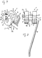
- the transport roller 1 consists essentially of two facing each other, each face disc-like outer flanges 2, 3, the above as fixed side parts designated elements, and from one intermediate middle part 4, the above as rotating Ring part designated element.
- the transport roller 1 stands over its through opening 6 with an arcuate Carrier element or bracket hook 8 of a bracket in Connection on which in the transport system in question Garments are promoted.
- the middle section 4 of the transport roller 1 on one explained in more detail below Catwalk of a conveyor of the transport system, at whose inclination is a movement of the transport roller 1 is possible.
- the support member 8 is in shape a coat hanger hook on the front Ends of the holder part 7.
- the bracket part 7 is a hollow cylindrical bushing, the end regions of which are each facing outwards are bent by riveting 24, 25.
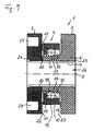
- FIG. 9 the Transport roller 1 shown in section. That between the first Flange 3 and the second flange 2 located middle part 4th has a one-sided elongated towards the second flange 2 Ring web 11 of the first disk-like flange 3 with a central hole as a through hole 6 uniform Diameter.
- the ring web 11 is from its connection on the first flange 3 to its free, perpendicular to Center axis 4 flattened end area 2 light on the outside inclined.
- the slightly inclined outer surface of the ring land 11 also provides the inner race 12 for the rolling elements 13, 14 of a rolling bearing. As a rule, a large number of Rolling elements necessary for a functional rolling bearing.
- the Inner tread 12 has a circumferential groove-shaped in the middle Indentation 18, which is the size of the outer surfaces of the rolling element 13, 14 is adapted and in which the rolling elements 13, 14 can move.
- the outside encloses the rotatable Circumferential part 15 in the form of an outer ring, the rolling elements 13, 14th radially spaced from the inner tread 12, and it has a disc-like angled perpendicular to the central axis 4 Side wall 21, which is on the with the smaller Diameter side of the ring web 11 is located.
- Side of the larger ring web diameter or to the first Flange 3 is directed, among other things, from the outer ring 15 Assembly reasons preferably open.
- the outer ring 15 is with each a slot-related minor game 16, 17 the inner surfaces 23, 22 of the first and second flanges 3, 2 provided.
- the outer ring 15 can on its pair of axial inner tread 10 also a circumferential groove-shaped depression 19 included, which also the surfaces of the rolling element 13, 14 is adapted.
- the second disc-shaped flange 2 through the mounting part 7 firmly held, the holding part 7 by a rigid riveting 24, 25 the second flange 2 to the end region 20 of the ring land 11 presses.
- a channel 26 is formed, in which the hook 8 of a hanger inserted and pushed so far the position of the hook 8 shown in FIG is obtained.
- the second flange 2 with Bar codes 37 may be provided.
- the second disc-shaped flange 2 has hole-like Cutouts 27, 28, in which instead of that in FIGS. 7, 8 Bar codes shown 37 electrical and electronic Coding devices comprising components (not shown) can be attached.
- the coding devices can, for example radial or circular inductive, magnetic and / or capacitive devices or pins material differing from the flange material, in order to be able to extract the stored information from it.
- the cutouts 27, 28 can also represent an annular groove, in which electrical components coupled with ROMand / or RAM memory modules can be inserted.
- the middle part four has at least one peripheral one annular peripheral part 15, which is separate from the two Flanges 2, 3 is rotatable, both flanges 2, 3 with each other and with the peripheral part 15 in such a connection stand that with a conveyor track support Rotation of the peripheral part 15 both flanges 2, 3 in one of rotation-independent idle state.
- the transport roller is based on the following inventive design of the transport system for transportation of clothes hanging in particular on hangers. In particular, this transport roller allows fixed External elements and rotating inner element direct Attack of a means of transport or a pushing device on the transport roller. A corresponding transport system is explained below with reference to FIGS. 1 to 6.
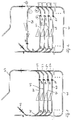
- FIG. 1 and 2 schematically show two general embodiments the transport device according to the invention for in particular of clothes hanging on hangers, the attachment 1 is provided for a one-step sorting, while Appendix 2 is intended for a two-stage sorting is.
- the transport system shown in Fig. 1 comprises one in one open circle guided conveyor track 41 with a drop point 42 at one end for unsorted goods and with one end 43 to discharge sorted goods. Between posting point 42 and the discharge end 43 of the conveyor track 41 are a plurality of parallel ones Throw lines are provided, of which only four in FIG. 1 Discharge lines 44 to 47 are shown.
- the discharge lines 44 up to 47 branches on the inlet side from the conveyor track 41 via switches 48 to 51 from.
- the discharge lines 44 to 47 go on the outlet side again via switches 52 to 55 into the conveyor track 41.
- Between The discharge lines 44 are their inlet and outlet to 47 each have a slope to the tapering Goods due to their gravity to the outlet side Turnouts 52 to 55 to transfer.
- a sorting agent has been created, which in the present case has one stage is referred to because the goods are one or more of the drop lines only happened once.
- Fig. 2 shows a modified design 1 with a two-stage sorting of goods.
- the transport system comprises according to Fig. 2 shows a return line 56, which is downstream of the discharge lines 44 to 47 via an inlet switch 57 with the conveyor track 41 communicates.
- the return line 56 upstream from the discharge lines 44 to 47 and downstream of the feed point 42 in connection with the randomlybahn 41.
- the return line 46 also includes Transporting goods down a slope that is opposite the gradients of the drop lines 44 to 47.
- each drop line 44 to 47 there is a collection point or a lock 58 is formed, with which over the discharge lines 44 to 47 incoming goods collected and targeted again in the Conveyor track 41 can be introduced.
- a similar collection point 62 is at the end of return line 56.
- the conveyor track 41 as well as the posting point 42 a profile rail 63 or 64 with a generally C-shaped Cross-section. Due to the C-shaped cross section, the profile rail 63 or 64 closed on all sides, except for one Gap 65 or 66, which is limited by the towards each other pointing edges of the C-shaped profile rail. Of these two Edge is the bottom or upward edge formed as a transport roller raceway 67 or 68.
- the career 67 or 68 thus forms the upper side of a runway 69 or 70, the one of the ends of the C-shaped to be facing each other Profile rail 63 with gap 65 therebetween or 68 forms. On this runway 69, 70 rides in Fig. 7 to 9 shown transport roller 1, of which in Fig.
- the roller bridge 69, 70 and the guide bridge 71, 72 interactively provide a lateral guidance for the transport roller 1 ready so that it does not extend to the side the profile rail 63, 64 can emerge in the gap 65, 66 however, they are essentially resistance-free, i.e. under rolling resistance able to run on track 67, 68. To this Rolling resistance comes at most when that on the transport rollers hanging goods pivoted sideways, a short-term Contact resistance between the two flanges 2, 3 and the webs 69 to 72.
- a link chain 73 which is spaced apart in the running direction Gears outside (as shown) or alternatively inside of the profile rail 63 and a not shown Electric motor drive is driven.
- the link chain 73 runs on the transport rollers Transferred by a comb-like conveyor 74, which in the Profile rail 63 runs along the gap 65 thereof.
- the comb-like Conveyor is by means of a connecting means, not shown connected to the link chain 73, which in the Profile rail is arranged and with an external link chain 73 a slot, also not shown, in the profile rail 63 passes through opposite to the gap 65.
- the Tines of the comb-like conveying member 74 run perpendicular to the Through opening 6 of the transport rollers running in the gap 63 and perpendicular to the transport roller raceway 68.
- the teeth of the comb-like Conveyor element as evenly spaced driving pins for the free end of the hook-shaped carrier element 6 of the goods holding part 7 of e.g. formed in the shape of a hanger.
- the intermediate spaces or gap spaces 78 of the tines or Driving pins, of which in Fig. 3 to 5 two pins with the Reference numerals 75 and 76 are designated, and the amount of these Spaces are chosen such that the free end of the support element in these rooms 78, coming from the loading point 42, is able to enter and then together with the respective transport roller and the goods attached to it are taken away.
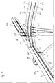
- the feed point 42 is, as stated above, by a Profile rail 64 with a C-shaped cross section corresponding to Profile rail 63 set.
- the profile rail 64 has at least in the area of the posting point 42, that is, where the Profile rail 64 opens laterally into profile rail 63, a slope, the lowest point at the confluence the profile rail 64 comes to lie in the profile rail 63. Because of this gradient, they move at the other end the profile rail 64 into these feed rollers gravity-driven with the hangers hanging on them down the slope.
- a restraint is at the drop point 42 formed in front of the mouth.
- This restraint comprises two retaining pins 84, 85 which are in the longitudinal direction the profile rail 64 one behind the other Distance are arranged.
- the retention pins 84, 85 are in on is known to be adjustable in terms of its axial position by means of drive cylinders 86, 87, with the aid of which the retaining pins 84, 85 optionally in a position in front of each Transport roller are slidable.
- Fig. 3 is the in relation to the conveying direction in the profile rail 64 front retaining pin 84 in front of the leading Transport roller 1, so that this against the retaining pin 84 abuts, while the rear retention pin 85 itself on the back of this transport roller 1 before the next one lagging transport roller 1 '.
- This is the leading one Transport roller 1 already from the trailing transport rollers 1 ', 1 "and 1"' separated, of which the roll 1 ' is retained by the rear retention pin 85 while the subsequent transport rollers 1 ", 1 '" to each other and to of the transport roller 1 '.
- a similar design of the transport system as for the The drop-off point can be found, for example, at the transition of the ejection lines 44 to 47 on the conveyor track 41. At this point if necessary, the switches 52 to 55 corresponding to the Profile rail 64 is formed at the feed point 42.
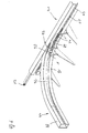
- the ejection line 44 in turn comprises a profile rail 88 similar curved course as the profile rail 64, which opens into the conveyor track.
- the profile rail 88 also opens into the profile rail 63, which the conveyor track 41 specifies.
- the profile rail 88 is used for rejection from transport rollers and the goods attached to them the conveyor track 41. Since not every transport roller from the profile rail 63 is to be transferred into the profile rail 88, is a switch between these two rails 63 and 68 educated. This switch consists of a swivel the profile rail 63 articulated roller web section 89 and a pivotable on the profile rail 63 guide web portion 90.
- the runway section forms 89 a part of the roller bar 69 of the profile rail 63, while the guide web portion 90 in the pivoted State part of the guide web 71 of the profile rail 63 forms.
- the roller bridge 69 and the guide bridge section 90 interrupts the guide web 71 and these sections 89, 90 of the turnout close in the swung out Position now on a roller bridge 91 or a guide bridge 92 of the profile rail 88, whereby arriving at the switch Transport rollers are diverted into the rail 88.
Landscapes
- Engineering & Computer Science (AREA)
- Mechanical Engineering (AREA)
- Chain Conveyers (AREA)
- Rollers For Roller Conveyors For Transfer (AREA)
- Warehouses Or Storage Devices (AREA)
- Intermediate Stations On Conveyors (AREA)
Applications Claiming Priority (2)
| Application Number | Priority Date | Filing Date | Title |
|---|---|---|---|
| DE10123598 | 2001-05-15 | ||
| DE10123598A DE10123598A1 (de) | 2001-05-15 | 2001-05-15 | Anlage zum Transport von Objekten auf Förderbahnen mittels einer förderkammangetriebenen Transportrolle |
Publications (2)
| Publication Number | Publication Date |
|---|---|
| EP1258439A1 true EP1258439A1 (fr) | 2002-11-20 |
| EP1258439B1 EP1258439B1 (fr) | 2003-09-17 |
Family
ID=7684862
Family Applications (1)
| Application Number | Title | Priority Date | Filing Date |
|---|---|---|---|
| EP02010464A Expired - Lifetime EP1258439B1 (fr) | 2001-05-15 | 2002-05-08 | Installation pour transporter des objets sur des voies de convoyage au moyen d'un rouleau de transport mû par came |
Country Status (7)
| Country | Link |
|---|---|
| US (1) | US6698575B2 (fr) |
| EP (1) | EP1258439B1 (fr) |
| JP (1) | JP4086542B2 (fr) |
| AT (1) | ATE249994T1 (fr) |
| DE (2) | DE10123598A1 (fr) |
| ES (1) | ES2206433T3 (fr) |
| PT (1) | PT1258439E (fr) |
Cited By (9)
| Publication number | Priority date | Publication date | Assignee | Title |
|---|---|---|---|---|
| EP1586517A1 (fr) * | 2004-04-16 | 2005-10-19 | Franz Gärtner | Système de transport pour rouleaux de transport |
| DE102005006455A1 (de) * | 2005-02-12 | 2006-08-24 | Dürkopp Adler AG | Transport-System für hängende Gegenstände |
| EP2196415A3 (fr) * | 2008-12-11 | 2012-05-30 | Dürkopp Fördertechnik GmbH | Station de chargement pour des sacs de transport transportés dans une installation de suspension et de transport |
| EP2886494A1 (fr) * | 2013-12-23 | 2015-06-24 | SDI Group Germany Material Handling Solutions GmbH | Dispositif de transport pour le transport d'objets suspendus |
| US10011425B2 (en) | 2016-03-29 | 2018-07-03 | Dematic Gmbh | Conveyor for conveying suspended objects |
| US10023386B2 (en) | 2016-03-29 | 2018-07-17 | Dematic Gmbh | Conveyor for conveying suspended objects |
| US10046914B1 (en) | 2017-11-03 | 2018-08-14 | Dematic Logistics Gmbh | Chain link, conveyor chain and conveyor apparatus |
| CN108584335A (zh) * | 2018-05-04 | 2018-09-28 | 浙江衣拿智能科技有限公司 | 一种跨流水线多点投放系统及方法 |
| CN108689134A (zh) * | 2018-05-04 | 2018-10-23 | 浙江衣拿智能科技有限公司 | 一种跨流水线多点转移系统及方法 |
Families Citing this family (13)
| Publication number | Priority date | Publication date | Assignee | Title |
|---|---|---|---|---|
| US20040173438A1 (en) * | 2003-03-07 | 2004-09-09 | Sdi Industries, Inc. | Trolley-less overhead conveyer system |
| US20040178048A1 (en) * | 2003-03-10 | 2004-09-16 | Sdi Industries, Inc. | Picker assembly |
| DE10320213A1 (de) * | 2003-05-05 | 2004-12-02 | Gärtner, Franz | Hängeförderbahnweiche |
| DE102006003270A1 (de) * | 2006-01-19 | 2007-08-02 | SSI Schäfer PEEM GmbH | Vorrichtung und Verfahren zum Sortieren von ungeordneten Behältern in einem Kommissioniersystem |
| DE102009009244A1 (de) * | 2009-02-17 | 2010-08-26 | Jürgen Löhrke GmbH | Reinigungssystem und Reinigungsverfahren |
| US8490774B2 (en) | 2011-02-24 | 2013-07-23 | Dürkopp Fördertechnik GmbH | Loading station for transport bags transported in an overhead conveyor system |
| AU2014348502B2 (en) * | 2013-11-15 | 2019-08-15 | Tangible Science, Inc. | Contact lens with a hydrophilic layer |
| DE102014205545B4 (de) * | 2014-03-25 | 2018-03-22 | Dürkopp Fördertechnik GmbH | Vorrichtung und Verfahren zum platzsparenden Anordnen von Hängewaren |
| CN106892248A (zh) * | 2017-02-24 | 2017-06-27 | 惠州市天泽盈丰物联网科技股份有限公司 | 制衣吊挂系统用连接组件和制衣吊挂系统 |
| CN108529157B (zh) * | 2018-05-04 | 2020-11-27 | 浙江衣拿智能科技股份有限公司 | 一种流水线投放转移系统及方法 |
| DE102018209268A1 (de) | 2018-06-11 | 2019-12-12 | Dürkopp Fördertechnik GmbH | Verfahren und Vorrichtung zum Erstellen von Aufträgen aus Einzelwaren |
| CN109250417B (zh) * | 2018-08-20 | 2021-09-28 | 浙江全佳服科技有限公司 | 一种自动上衣装置 |
| CN110255119A (zh) * | 2019-06-19 | 2019-09-20 | 徐州嘉搏纺织股份有限公司 | 一种用于便于使用的高效生产针织品吊挂系统 |
Citations (2)
| Publication number | Priority date | Publication date | Assignee | Title |
|---|---|---|---|---|
| EP0451581A1 (fr) * | 1990-03-28 | 1991-10-16 | Banss Maschinenfabrik GmbH & Co. KG | Transporteur pour abattoirs ou entrepôts frigorifiques pour la conservation de la viande |
| EP1013569A1 (fr) | 1998-12-22 | 2000-06-28 | Franz Gärtner | Rouleau de transport utilisé sur des voies de convoyage dans des installations pour transporter des objets |
Family Cites Families (4)
| Publication number | Priority date | Publication date | Assignee | Title |
|---|---|---|---|---|
| US3844406A (en) * | 1972-11-17 | 1974-10-29 | Kornylah Corp | Rotating cable conveyor |
| DE4319164C2 (de) * | 1993-06-09 | 1996-03-21 | Duerkopp Adler Ag | Förderer, insbesondere Stetigförderer für Einzelbügel |
| SE509407C2 (sv) * | 1997-05-26 | 1999-01-25 | Metric Interconveyor Ab | Medbringar - och avlastningssystem för galgar |
| SE513797C2 (sv) * | 1999-03-03 | 2000-11-06 | Jensen Sweden Ab | Transportör för klädgalgar |
-
2001
- 2001-05-15 DE DE10123598A patent/DE10123598A1/de not_active Withdrawn
-
2002
- 2002-05-08 DE DE50200045T patent/DE50200045D1/de not_active Expired - Lifetime
- 2002-05-08 AT AT02010464T patent/ATE249994T1/de not_active IP Right Cessation
- 2002-05-08 EP EP02010464A patent/EP1258439B1/fr not_active Expired - Lifetime
- 2002-05-08 PT PT02010464T patent/PT1258439E/pt unknown
- 2002-05-08 ES ES02010464T patent/ES2206433T3/es not_active Expired - Lifetime
- 2002-05-14 US US10/146,666 patent/US6698575B2/en not_active Expired - Fee Related
- 2002-05-15 JP JP2002139878A patent/JP4086542B2/ja not_active Expired - Fee Related
Patent Citations (2)
| Publication number | Priority date | Publication date | Assignee | Title |
|---|---|---|---|---|
| EP0451581A1 (fr) * | 1990-03-28 | 1991-10-16 | Banss Maschinenfabrik GmbH & Co. KG | Transporteur pour abattoirs ou entrepôts frigorifiques pour la conservation de la viande |
| EP1013569A1 (fr) | 1998-12-22 | 2000-06-28 | Franz Gärtner | Rouleau de transport utilisé sur des voies de convoyage dans des installations pour transporter des objets |
Cited By (11)
| Publication number | Priority date | Publication date | Assignee | Title |
|---|---|---|---|---|
| EP1586517A1 (fr) * | 2004-04-16 | 2005-10-19 | Franz Gärtner | Système de transport pour rouleaux de transport |
| DE102005006455A1 (de) * | 2005-02-12 | 2006-08-24 | Dürkopp Adler AG | Transport-System für hängende Gegenstände |
| EP2196415A3 (fr) * | 2008-12-11 | 2012-05-30 | Dürkopp Fördertechnik GmbH | Station de chargement pour des sacs de transport transportés dans une installation de suspension et de transport |
| EP2886494A1 (fr) * | 2013-12-23 | 2015-06-24 | SDI Group Germany Material Handling Solutions GmbH | Dispositif de transport pour le transport d'objets suspendus |
| US9205992B2 (en) | 2013-12-23 | 2015-12-08 | Sdi Group Germany Material Handling | Conveyor for conveying hanging objects |
| US10011425B2 (en) | 2016-03-29 | 2018-07-03 | Dematic Gmbh | Conveyor for conveying suspended objects |
| US10023386B2 (en) | 2016-03-29 | 2018-07-17 | Dematic Gmbh | Conveyor for conveying suspended objects |
| US10046914B1 (en) | 2017-11-03 | 2018-08-14 | Dematic Logistics Gmbh | Chain link, conveyor chain and conveyor apparatus |
| CN108584335A (zh) * | 2018-05-04 | 2018-09-28 | 浙江衣拿智能科技有限公司 | 一种跨流水线多点投放系统及方法 |
| CN108689134A (zh) * | 2018-05-04 | 2018-10-23 | 浙江衣拿智能科技有限公司 | 一种跨流水线多点转移系统及方法 |
| CN108584335B (zh) * | 2018-05-04 | 2019-12-27 | 浙江衣拿智能科技有限公司 | 一种跨流水线多点投放系统及方法 |
Also Published As
| Publication number | Publication date |
|---|---|
| EP1258439B1 (fr) | 2003-09-17 |
| US20030000806A1 (en) | 2003-01-02 |
| JP4086542B2 (ja) | 2008-05-14 |
| JP2002347912A (ja) | 2002-12-04 |
| US6698575B2 (en) | 2004-03-02 |
| PT1258439E (pt) | 2004-02-27 |
| DE10123598A1 (de) | 2002-11-21 |
| ES2206433T3 (es) | 2004-05-16 |
| DE50200045D1 (de) | 2003-10-23 |
| ATE249994T1 (de) | 2003-10-15 |
Similar Documents
| Publication | Publication Date | Title |
|---|---|---|
| EP1258439B1 (fr) | Installation pour transporter des objets sur des voies de convoyage au moyen d'un rouleau de transport mû par came | |
| EP0912426B1 (fr) | Procede de transport suspendu de recipients et dispositif approprie pour mettre ledit procede en oeuvre | |
| DE19523164B4 (de) | Flexibles Fördersystem | |
| DE102016113180B4 (de) | Vorrichtung zum Fördern und Sortieren von Stückgütern und Verfahren zum Sortieren von Stückgütern | |
| EP3225572B1 (fr) | Dispositif de transport d'objets suspendus | |
| EP1169249B1 (fr) | Procede et dispositif pour transporter des produits en vrac | |
| DE2110198B2 (de) | Gruppiervorrichtung fuer gegenstaende wie z.b. flaschen | |
| EP3818001A1 (fr) | Station de chargement de cintre pour convoyeur suspendu | |
| DE3135930A1 (de) | Verfahren zum verarbeiten von druckbogen | |
| EP2121489B1 (fr) | Convoyeur pour le transport de supports d'articles a transporter le long d'une voie de transport | |
| DE10317417B4 (de) | Vereinzelungs- und Fördervorrichtung | |
| DE3714108A1 (de) | Vorrichtung zur uebergabe von werkstuecktraegern | |
| EP0104366A1 (fr) | Convoyeur en continu, notamment convoyeur à chaînes porteuses | |
| EP2121488B1 (fr) | Separateur et convoyeur suspendu equipe de ce separateur | |
| DE10309186A1 (de) | Hängefördereinrichtung | |
| EP2117973B1 (fr) | Convoyeur suspendu avec dispositif d'aiguillage d'introduction | |
| DE20108190U1 (de) | Anlage zum Transport von Objekten auf Förderbahnen mittels einer Transportrolle | |
| DE19624503A1 (de) | Hängefördereinrichtung | |
| EP1571106B1 (fr) | Transporteur à vis pour des cintres à vêtements | |
| EP1915306A1 (fr) | Systeme de transport | |
| DE3938548C2 (de) | Vorrichtung zum Gruppieren gleichartiger Waren | |
| WO2004020317A2 (fr) | Systeme de transport concu pour transporter notamment de maniere suspendue des produits a transporter | |
| DE602005001146T2 (de) | Vorrichtung zum Überführen eines mehrreihigen Stromes aufrechtstehender Gegenstände, insbesondere Flaschen, in eine einzige Reihe | |
| EP2367745B1 (fr) | Dispositif et procédé de transfert d'objets plats flexibles | |
| DE19912391A1 (de) | Rollenbahn oder Rollenbahnabschnitt |
Legal Events
| Date | Code | Title | Description |
|---|---|---|---|
| PUAI | Public reference made under article 153(3) epc to a published international application that has entered the european phase |
Free format text: ORIGINAL CODE: 0009012 |
|
| AK | Designated contracting states |
Kind code of ref document: A1 Designated state(s): AT BE CH CY DE DK ES FI FR GB GR IE IT LI LU MC NL PT SE TR |
|
| AX | Request for extension of the european patent |
Free format text: AL;LT;LV;MK;RO;SI |
|
| 17P | Request for examination filed |
Effective date: 20030114 |
|
| GRAH | Despatch of communication of intention to grant a patent |
Free format text: ORIGINAL CODE: EPIDOS IGRA |
|
| GRAS | Grant fee paid |
Free format text: ORIGINAL CODE: EPIDOSNIGR3 |
|
| GRAA | (expected) grant |
Free format text: ORIGINAL CODE: 0009210 |
|
| AKX | Designation fees paid |
Designated state(s): AT BE CH CY DE DK ES FI FR GB GR IE IT LI LU MC NL PT SE TR |
|
| AK | Designated contracting states |
Kind code of ref document: B1 Designated state(s): AT BE CH CY DE DK ES FI FR GB GR IE IT LI LU MC NL PT SE TR |
|
| PG25 | Lapsed in a contracting state [announced via postgrant information from national office to epo] |
Ref country code: IE Free format text: LAPSE BECAUSE OF FAILURE TO SUBMIT A TRANSLATION OF THE DESCRIPTION OR TO PAY THE FEE WITHIN THE PRESCRIBED TIME-LIMIT Effective date: 20030917 Ref country code: CY Free format text: LAPSE BECAUSE OF FAILURE TO SUBMIT A TRANSLATION OF THE DESCRIPTION OR TO PAY THE FEE WITHIN THE PRESCRIBED TIME-LIMIT Effective date: 20030917 Ref country code: FI Free format text: LAPSE BECAUSE OF FAILURE TO SUBMIT A TRANSLATION OF THE DESCRIPTION OR TO PAY THE FEE WITHIN THE PRESCRIBED TIME-LIMIT Effective date: 20030917 Ref country code: TR Free format text: LAPSE BECAUSE OF FAILURE TO SUBMIT A TRANSLATION OF THE DESCRIPTION OR TO PAY THE FEE WITHIN THE PRESCRIBED TIME-LIMIT Effective date: 20030917 |
|
| REG | Reference to a national code |
Ref country code: GB Ref legal event code: FG4D Free format text: NOT ENGLISH |
|
| REG | Reference to a national code |
Ref country code: CH Ref legal event code: NV Representative=s name: TROESCH SCHEIDEGGER WERNER AG Ref country code: CH Ref legal event code: EP |
|
| REF | Corresponds to: |
Ref document number: 50200045 Country of ref document: DE Date of ref document: 20031023 Kind code of ref document: P |
|
| REG | Reference to a national code |
Ref country code: IE Ref legal event code: FG4D Free format text: GERMAN |
|
| PG25 | Lapsed in a contracting state [announced via postgrant information from national office to epo] |
Ref country code: DK Free format text: LAPSE BECAUSE OF FAILURE TO SUBMIT A TRANSLATION OF THE DESCRIPTION OR TO PAY THE FEE WITHIN THE PRESCRIBED TIME-LIMIT Effective date: 20031217 Ref country code: SE Free format text: LAPSE BECAUSE OF FAILURE TO SUBMIT A TRANSLATION OF THE DESCRIPTION OR TO PAY THE FEE WITHIN THE PRESCRIBED TIME-LIMIT Effective date: 20031217 Ref country code: GR Free format text: LAPSE BECAUSE OF FAILURE TO SUBMIT A TRANSLATION OF THE DESCRIPTION OR TO PAY THE FEE WITHIN THE PRESCRIBED TIME-LIMIT Effective date: 20031217 |
|
| GBT | Gb: translation of ep patent filed (gb section 77(6)(a)/1977) |
Effective date: 20031217 |
|
| REG | Reference to a national code |
Ref country code: IE Ref legal event code: FD4D |
|
| PG25 | Lapsed in a contracting state [announced via postgrant information from national office to epo] |
Ref country code: LU Free format text: LAPSE BECAUSE OF NON-PAYMENT OF DUE FEES Effective date: 20040508 |
|
| REG | Reference to a national code |
Ref country code: ES Ref legal event code: FG2A Ref document number: 2206433 Country of ref document: ES Kind code of ref document: T3 |
|
| PG25 | Lapsed in a contracting state [announced via postgrant information from national office to epo] |
Ref country code: MC Free format text: LAPSE BECAUSE OF NON-PAYMENT OF DUE FEES Effective date: 20040531 |
|
| ET | Fr: translation filed | ||
| PLBE | No opposition filed within time limit |
Free format text: ORIGINAL CODE: 0009261 |
|
| STAA | Information on the status of an ep patent application or granted ep patent |
Free format text: STATUS: NO OPPOSITION FILED WITHIN TIME LIMIT |
|
| 26N | No opposition filed |
Effective date: 20040618 |
|
| PGFP | Annual fee paid to national office [announced via postgrant information from national office to epo] |
Ref country code: PT Payment date: 20050413 Year of fee payment: 4 |
|
| PGFP | Annual fee paid to national office [announced via postgrant information from national office to epo] |
Ref country code: BE Payment date: 20050511 Year of fee payment: 4 |
|
| PGFP | Annual fee paid to national office [announced via postgrant information from national office to epo] |
Ref country code: AT Payment date: 20050513 Year of fee payment: 4 |
|
| PG25 | Lapsed in a contracting state [announced via postgrant information from national office to epo] |
Ref country code: AT Free format text: LAPSE BECAUSE OF NON-PAYMENT OF DUE FEES Effective date: 20060508 |
|
| PG25 | Lapsed in a contracting state [announced via postgrant information from national office to epo] |
Ref country code: CH Free format text: LAPSE BECAUSE OF NON-PAYMENT OF DUE FEES Effective date: 20060531 Ref country code: BE Free format text: LAPSE BECAUSE OF NON-PAYMENT OF DUE FEES Effective date: 20060531 Ref country code: LI Free format text: LAPSE BECAUSE OF NON-PAYMENT OF DUE FEES Effective date: 20060531 |
|
| PG25 | Lapsed in a contracting state [announced via postgrant information from national office to epo] |
Ref country code: PT Free format text: LAPSE BECAUSE OF NON-PAYMENT OF DUE FEES Effective date: 20061108 |
|
| PG25 | Lapsed in a contracting state [announced via postgrant information from national office to epo] |
Ref country code: NL Free format text: LAPSE BECAUSE OF NON-PAYMENT OF DUE FEES Effective date: 20061201 |
|
| REG | Reference to a national code |
Ref country code: PT Ref legal event code: MM4A Free format text: LAPSE DUE TO NON-PAYMENT OF FEES Effective date: 20061108 |
|
| REG | Reference to a national code |
Ref country code: CH Ref legal event code: PL |
|
| NLV4 | Nl: lapsed or anulled due to non-payment of the annual fee |
Effective date: 20061201 |
|
| BERE | Be: lapsed |
Owner name: *GARTNER FRANZ Effective date: 20060531 |
|
| PGFP | Annual fee paid to national office [announced via postgrant information from national office to epo] |
Ref country code: FR Payment date: 20120614 Year of fee payment: 11 Ref country code: GB Payment date: 20120523 Year of fee payment: 11 |
|
| PGFP | Annual fee paid to national office [announced via postgrant information from national office to epo] |
Ref country code: IT Payment date: 20120521 Year of fee payment: 11 |
|
| PGFP | Annual fee paid to national office [announced via postgrant information from national office to epo] |
Ref country code: ES Payment date: 20120523 Year of fee payment: 11 |
|
| GBPC | Gb: european patent ceased through non-payment of renewal fee |
Effective date: 20130508 |
|
| PG25 | Lapsed in a contracting state [announced via postgrant information from national office to epo] |
Ref country code: IT Free format text: LAPSE BECAUSE OF NON-PAYMENT OF DUE FEES Effective date: 20130508 |
|
| REG | Reference to a national code |
Ref country code: FR Ref legal event code: ST Effective date: 20140131 |
|
| REG | Reference to a national code |
Ref country code: DE Ref legal event code: R082 Ref document number: 50200045 Country of ref document: DE Representative=s name: SOMMER, PETER, DIPL.-WIRTSCH.-ING., DE |
|
| PG25 | Lapsed in a contracting state [announced via postgrant information from national office to epo] |
Ref country code: GB Free format text: LAPSE BECAUSE OF NON-PAYMENT OF DUE FEES Effective date: 20130508 |
|
| REG | Reference to a national code |
Ref country code: DE Ref legal event code: R081 Ref document number: 50200045 Country of ref document: DE Owner name: PSB INTRALOGISTICS GMBH, DE Free format text: FORMER OWNER: GAERTNER, FRANZ, 97656 OBERELSBACH, DE Effective date: 20140408 Ref country code: DE Ref legal event code: R082 Ref document number: 50200045 Country of ref document: DE Representative=s name: SOMMER, PETER, DIPL.-WIRTSCH.-ING., DE Effective date: 20140408 Ref country code: DE Ref legal event code: R082 Ref document number: 50200045 Country of ref document: DE Representative=s name: VIERING, JENTSCHURA & PARTNER PATENT- UND RECH, DE Effective date: 20140408 Ref country code: DE Ref legal event code: R082 Ref document number: 50200045 Country of ref document: DE Representative=s name: VIERING, JENTSCHURA & PARTNER MBB PATENT- UND , DE Effective date: 20140408 |
|
| PG25 | Lapsed in a contracting state [announced via postgrant information from national office to epo] |
Ref country code: FR Free format text: LAPSE BECAUSE OF NON-PAYMENT OF DUE FEES Effective date: 20130531 |
|
| REG | Reference to a national code |
Ref country code: ES Ref legal event code: FD2A Effective date: 20140613 |
|
| REG | Reference to a national code |
Ref country code: DE Ref legal event code: R082 Ref document number: 50200045 Country of ref document: DE Representative=s name: VIERING, JENTSCHURA & PARTNER PATENT- UND RECH, DE Ref country code: DE Ref legal event code: R082 Ref document number: 50200045 Country of ref document: DE Representative=s name: VIERING, JENTSCHURA & PARTNER MBB PATENT- UND , DE |
|
| PG25 | Lapsed in a contracting state [announced via postgrant information from national office to epo] |
Ref country code: ES Free format text: LAPSE BECAUSE OF NON-PAYMENT OF DUE FEES Effective date: 20130509 |
|
| PGFP | Annual fee paid to national office [announced via postgrant information from national office to epo] |
Ref country code: DE Payment date: 20170530 Year of fee payment: 16 |
|
| REG | Reference to a national code |
Ref country code: DE Ref legal event code: R119 Ref document number: 50200045 Country of ref document: DE |
|
| PG25 | Lapsed in a contracting state [announced via postgrant information from national office to epo] |
Ref country code: DE Free format text: LAPSE BECAUSE OF NON-PAYMENT OF DUE FEES Effective date: 20181201 |