EP1258643B1 - Vis à billes - Google Patents
Vis à billes Download PDFInfo
- Publication number
- EP1258643B1 EP1258643B1 EP02010749A EP02010749A EP1258643B1 EP 1258643 B1 EP1258643 B1 EP 1258643B1 EP 02010749 A EP02010749 A EP 02010749A EP 02010749 A EP02010749 A EP 02010749A EP 1258643 B1 EP1258643 B1 EP 1258643B1
- Authority
- EP
- European Patent Office
- Prior art keywords
- lubricant
- ball screw
- ball nut
- cylinder
- ball
- Prior art date
- Legal status (The legal status is an assumption and is not a legal conclusion. Google has not performed a legal analysis and makes no representation as to the accuracy of the status listed.)
- Expired - Lifetime
Links
- 239000000314 lubricant Substances 0.000 claims description 107
- 238000005096 rolling process Methods 0.000 claims description 16
- 238000001914 filtration Methods 0.000 claims description 2
- 239000004519 grease Substances 0.000 description 20
- 210000002445 nipple Anatomy 0.000 description 8
- 230000002093 peripheral effect Effects 0.000 description 5
- 239000000843 powder Substances 0.000 description 3
- 239000000126 substance Substances 0.000 description 3
- 241001391944 Commicarpus scandens Species 0.000 description 1
- 230000015572 biosynthetic process Effects 0.000 description 1
- 238000004140 cleaning Methods 0.000 description 1
- 230000000694 effects Effects 0.000 description 1
- 238000007789 sealing Methods 0.000 description 1
Images


Classifications
-
- F—MECHANICAL ENGINEERING; LIGHTING; HEATING; WEAPONS; BLASTING
- F16—ENGINEERING ELEMENTS AND UNITS; GENERAL MEASURES FOR PRODUCING AND MAINTAINING EFFECTIVE FUNCTIONING OF MACHINES OR INSTALLATIONS; THERMAL INSULATION IN GENERAL
- F16H—GEARING
- F16H25/00—Gearings comprising primarily only cams, cam-followers and screw-and-nut mechanisms
- F16H25/18—Gearings comprising primarily only cams, cam-followers and screw-and-nut mechanisms for conveying or interconverting oscillating or reciprocating motions
- F16H25/20—Screw mechanisms
- F16H25/22—Screw mechanisms with balls, rollers, or similar members between the co-operating parts; Elements essential to the use of such members
- F16H25/2204—Screw mechanisms with balls, rollers, or similar members between the co-operating parts; Elements essential to the use of such members with balls
-
- F—MECHANICAL ENGINEERING; LIGHTING; HEATING; WEAPONS; BLASTING
- F16—ENGINEERING ELEMENTS AND UNITS; GENERAL MEASURES FOR PRODUCING AND MAINTAINING EFFECTIVE FUNCTIONING OF MACHINES OR INSTALLATIONS; THERMAL INSULATION IN GENERAL
- F16H—GEARING
- F16H57/00—General details of gearing
- F16H57/04—Features relating to lubrication or cooling or heating
- F16H57/048—Type of gearings to be lubricated, cooled or heated
- F16H57/0497—Screw mechanisms
-
- Y—GENERAL TAGGING OF NEW TECHNOLOGICAL DEVELOPMENTS; GENERAL TAGGING OF CROSS-SECTIONAL TECHNOLOGIES SPANNING OVER SEVERAL SECTIONS OF THE IPC; TECHNICAL SUBJECTS COVERED BY FORMER USPC CROSS-REFERENCE ART COLLECTIONS [XRACs] AND DIGESTS
- Y10—TECHNICAL SUBJECTS COVERED BY FORMER USPC
- Y10T—TECHNICAL SUBJECTS COVERED BY FORMER US CLASSIFICATION
- Y10T74/00—Machine element or mechanism
- Y10T74/18—Mechanical movements
- Y10T74/18568—Reciprocating or oscillating to or from alternating rotary
- Y10T74/18576—Reciprocating or oscillating to or from alternating rotary including screw and nut
- Y10T74/186—Alternate power path operable on failure of primary
-
- Y—GENERAL TAGGING OF NEW TECHNOLOGICAL DEVELOPMENTS; GENERAL TAGGING OF CROSS-SECTIONAL TECHNOLOGIES SPANNING OVER SEVERAL SECTIONS OF THE IPC; TECHNICAL SUBJECTS COVERED BY FORMER USPC CROSS-REFERENCE ART COLLECTIONS [XRACs] AND DIGESTS
- Y10—TECHNICAL SUBJECTS COVERED BY FORMER USPC
- Y10T—TECHNICAL SUBJECTS COVERED BY FORMER US CLASSIFICATION
- Y10T74/00—Machine element or mechanism
- Y10T74/18—Mechanical movements
- Y10T74/18568—Reciprocating or oscillating to or from alternating rotary
- Y10T74/18576—Reciprocating or oscillating to or from alternating rotary including screw and nut
- Y10T74/18712—Contamination related
-
- Y—GENERAL TAGGING OF NEW TECHNOLOGICAL DEVELOPMENTS; GENERAL TAGGING OF CROSS-SECTIONAL TECHNOLOGIES SPANNING OVER SEVERAL SECTIONS OF THE IPC; TECHNICAL SUBJECTS COVERED BY FORMER USPC CROSS-REFERENCE ART COLLECTIONS [XRACs] AND DIGESTS
- Y10—TECHNICAL SUBJECTS COVERED BY FORMER USPC
- Y10T—TECHNICAL SUBJECTS COVERED BY FORMER US CLASSIFICATION
- Y10T74/00—Machine element or mechanism
- Y10T74/18—Mechanical movements
- Y10T74/18568—Reciprocating or oscillating to or from alternating rotary
- Y10T74/18576—Reciprocating or oscillating to or from alternating rotary including screw and nut
- Y10T74/18712—Contamination related
- Y10T74/1872—Imperforate enclosure
-
- Y—GENERAL TAGGING OF NEW TECHNOLOGICAL DEVELOPMENTS; GENERAL TAGGING OF CROSS-SECTIONAL TECHNOLOGIES SPANNING OVER SEVERAL SECTIONS OF THE IPC; TECHNICAL SUBJECTS COVERED BY FORMER USPC CROSS-REFERENCE ART COLLECTIONS [XRACs] AND DIGESTS
- Y10—TECHNICAL SUBJECTS COVERED BY FORMER USPC
- Y10T—TECHNICAL SUBJECTS COVERED BY FORMER US CLASSIFICATION
- Y10T74/00—Machine element or mechanism
- Y10T74/18—Mechanical movements
- Y10T74/18568—Reciprocating or oscillating to or from alternating rotary
- Y10T74/18576—Reciprocating or oscillating to or from alternating rotary including screw and nut
- Y10T74/18744—Lubrication
-
- Y—GENERAL TAGGING OF NEW TECHNOLOGICAL DEVELOPMENTS; GENERAL TAGGING OF CROSS-SECTIONAL TECHNOLOGIES SPANNING OVER SEVERAL SECTIONS OF THE IPC; TECHNICAL SUBJECTS COVERED BY FORMER USPC CROSS-REFERENCE ART COLLECTIONS [XRACs] AND DIGESTS
- Y10—TECHNICAL SUBJECTS COVERED BY FORMER USPC
- Y10T—TECHNICAL SUBJECTS COVERED BY FORMER US CLASSIFICATION
- Y10T74/00—Machine element or mechanism
- Y10T74/19—Gearing
- Y10T74/19642—Directly cooperating gears
- Y10T74/19698—Spiral
- Y10T74/19702—Screw and nut
- Y10T74/19744—Rolling element engaging thread
Definitions
- the present invention relates to a ball screw and, in particular, to an improvement in lubricant supply means which supplies lubricant such as grease into between a ball screw shaft and a ball nut.
- a ball screw for use in table feed apparatus is conventionally structured in such a manner as shown in Fig. 6.
- reference character 11 designates a ball screw shaft
- 12 designates a ball nut
- 13 designates a plurality of balls serving as rolling elements .
- first spiral groove 14 in the outer peripheral surface of the ball screw shaft 11
- second spiral groove 15 in the inner peripheral surface of the ball nut 12
- the balls 13 are allowed to roll along rolling passages respectively formed between the second and first spiral grooves 15 and 14.
- rolling body circulation passages (not shown).
- the balls 13 are allowed to roll repeatedly along the rolling passages which are formed between the first and second spiral grooves 14 and 15, and the rolling body circulation passages.
- a pulley 16 is mounted on the ball nut 12, and, in case where the pulley 16 is rotated by a motor 19 through a belt 17 and another pulley 18, the balls 13 are allowed to roll repeatedly between the first and second spiral grooves 14 and 15. With the repeated rolling movements of the balls 13, the ball screw shaft 11 is moved in the axial direction thereof with respect to the ball nut 12.
- reference character 20 designates a seal member for sealing a clearance between the ball screw shaft 11 and ball nut 12.
- a grease nipple 21 is mounted on the ball nut 12. That is, lubricant such as grease is supplied from the grease nipple 21 into the interior portion of the ball nut 12 to thereby control the wear of the ball screw shaft 11 and ball nut 12.
- lubricant such as grease is supplied from the grease nipple 21 into the interior portion of the ball nut 12 to thereby control the wear of the ball screw shaft 11 and ball nut 12.
- an oil film is easy to break and thus the lubricant must be supplied frequently into the interior portion of the ball nut 12 in order to prevent such oil film breakage, which results in a large amount of lubricant used.
- WO-A-0029764 discloses a cup inserted in a bore of the screw, whereas a flange and a sleeve form an annular ring in which the free ends of the screw are inserted.
- the corresponding cup contains grease lubricant that may bleed under the influence of centrifugal forces or increased temperature through apertures towards the raceways and balls through a corresponding annulus defined between bore and cup.
- the lubricant filled into the lubricant filling and storing space is pushed out from this space, and the lubricant is allowed to flow between the ball screw shaft and cylinder, then the lubricant is supplied into the interior portion of the ball nut. Therefore, the lubricant can be supplied into the interior portion of the ball nut without supplying the lubricant from a greased nipple mounted on the ball nut. That eliminates the need to fill and store and extra amount of lubricant in the interior portion of the ball nut, thereby being able to reduce the supply amount of lubricant to be supplied into the interior portion of the ball nut.
- the lubricant supplied into the interior portion of the ball nut can be collected from the lubricant discharge opening.
- lubricant discharged from the lubricant discharge opening can be supplied again into the interior portion of the ball nut from the lubricant filling and storing space.
- Fig. 1 shows a first embodiment of a ball screw according to the present invention.
- reference character 11 designates a ball screw shaft
- 12 designates a ball nut
- 13 designates a plurality of balls serving as rolling elements; and, in the outer peripheral surface of the ball screw shaft 11, there are formed first spiral groove 14.
- the balls 13 are allowed to roll along rolling passages which are respectively formed between the second and first spiral grooves 15 and 14. Also, in the interior portion of the ball nut 12, there are formed rolling body circulation passages (not shown). The balls 13 are allowed to roll repeatedly along the rolling passages which are formed between the first and second spiral grooves 14 and 15, and the rolling body circulation passages. Further, a pulley 16 is mounted on the ball nut 12, and, in case where the pulley 16 is rotated by a motor 19 through a belt 17 and another pulley 18, the balls 13 are allowed to roll repeatedly between the first and second spiral grooves 14 and 15.
- reference character 20 designates a seal member which seals a clearance between the ball screw shaft 11 and ball nut 12.
- a cylindrical-shaped cylinder 22 On the outer periphery of the ball screw shaft 11, there is disposed a cylindrical-shaped cylinder 22. One end of the cylinder 22 is fixed to the end face of the ball nut 12, whereby the cylinder 22 can be rotated integrally with the ball nut 12. On the other hand, the other end of the cylinder 22 is closed by an end plate 23. Between the end plate 23 serving as the closed end portion of the cylinder 22 and the leading end face of the ball screw shaft 11, there is formed a lubricant filling and storing space 24.
- lubricant filling space 24 Into the lubricant filling and storing space 24, in the following abbreviated as lubricant filling space 24, there can be supplied lubricant such as grease from a grease nipple 21 which is disposed on the closed-side end portion of the cylinder 22 and is used as lubricant supply means (unit).
- lubricant such as grease from a grease nipple 21 which is disposed on the closed-side end portion of the cylinder 22 and is used as lubricant supply means (unit).
- Fig. 2A shows the state of the present ball screw in which lubricant G such as grease is filled into the lubricant filling space 24 from the grease nipple 21 disposed on the cylinder 22.
- lubricant G such as grease
- the ball nut 12 and cylinder 22 are rotated by a motor 19 to thereby approach the leading end face of the ball screw shaft 11 toward the end plate 23, as shown in Fig. 2B, the lubricant G filled and stored in the lubricant filling space 24 is pushed out from the lubricant filling space 24.
- the lubricant G pushed out from the lubricant filing space 24 is made to flow between the ball screw shaft 11 and cylinder 22 and is then supplied into the interior portion of the ball nut 12. Therefore, even in case where the lubricant is not supplied from the grease nipple 21 mounted on the ball nut 12, the lubricant G can be supplied into the interior portion of the ball nut 12.
- the present embodiment there is eliminated the need to fill and store an extra amount of lubricant in the interior portion of the ball nut 12, which can reduce the supply amount of the lubricant to be supplied into the interior portion of the ball nut 12.
- the periphery of the ball nut 12 can be prevented from being soiled with the lubricant pushed out from the interior portion of the ball nut 12. Further, by adjusting the amount of the lubricant G pushed out from the lubricant filling space 24, the deteriorated lubricant G can be removed from the interior portion of the ball nut 12.
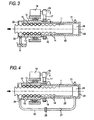
- FIG. 3 shows a schematic structure view of a second embodiment of a ball screw according to the present invention.
- the second embodiment is different from the previously-described first embodiment in that a lubricant discharge opening 25 is formed in the end portion of the ball nut 12 situated on the opposite side to the cylinder 22.
- the remaining portions of the second embodiment are similar in structure to the first embodiment.
- the lubricant discharge opening 25 is formed in the end portion of the ball nut 12 situated on the opposite side to the cylinder 22, the lubricant G supplied into the interior portion of the ball nut 12 can be discharged from the lubricant discharge opening 25.
- the lubricant G supplied from the lubricant filling space 24 into the interior portion of the ball nut 12 can be collected.
- the old lubricant within the ball nut 12 can be discharged from the lubricant discharge opening 25. it is possible to clean the interior portion of the ball nut 12 with the lubricant.
- the structure is arranged such that new lubricant is allowed to start flowing at and from the large load distribution area of the interior portion of the ball nut 12, there can be obtained a better cleaning effect.
- Fig. 4 shows a schematic structure view of a third embodiment of a ball screw according to the present invention.
- the third embodiment is different from the previously-described second embodiment in that a pipe passage 26 for returning the lubricant discharged from the lubricant discharge opening 25 to the lubricant filling space 24 is formed on the outside of the cylinder 22.
- a check valve 27 and a filter 28 which is used as lubricant filtering means(unit).
- the remaining portions of the third embodiment are similar in structure to the second embodiment.
- the lubricant discharged from the lubricant discharge opening 25 is returned through the pipe passage 26 to the lubricant filling space 24, the lubricant discharged from the lubricant discharge opening 25 can be supplied again into the interior portion of the ball nut 12. Also, the provision of the filter 28 on the pipe passage 26 makes it possible to remove polluting substances such as worn powder from the lubricant.
- the lubricant G filled into the lubricant filling space 24 is pushed out from the lubricant filling space 24, and the lubricant G is then supplied into the interior portion of the ball nut 12.
- the lubricant G may be previously filled and stored into a space between stroke A (the normal stroke range of the ball screw shaft 11) and stroke B (the stroke of the ball screw shaft 11 in the lubricant supply time thereof) of the lubricant filling space 24. Then, as the need for the lubricant arises, the ball screw shaft 11 may be moved or stroked up to stroke B in Fig. 5 to thereby supply the lubricant G into the interior portion of the ball nut 12.
- the lubricant can be supplied into the interior portion of the ball nut without supplying the lubricant from the grease nipple mounted on the ball nut.
- This eliminates the need to fill and store an extra amount of lubricant in the interior portion of the ball nut, thereby being able to reduce the supply amount of lubricant to be supplied into the interior portion of the ball nut.
- the lubricant discharged from the lubricant discharge opening can be supplied again into the interior portion of the ball nut from the lubricant filling space.
- the lubricant discharged from the lubricant discharge opening can be supplied again into the interior portion of the ball nut from the lubricant filling space.
- Polluting substances such as worn powder can be removed from the lubricant.
Landscapes
- Engineering & Computer Science (AREA)
- General Engineering & Computer Science (AREA)
- Mechanical Engineering (AREA)
- Transmission Devices (AREA)
Claims (5)
- Vis à billes comprenant :un axe de vis à billes (11) ayant une première rainure hélicoïdale (14) formée sur une périphérie extérieure de celui-ci ;un écrou sphérique (12) ayant une seconde rainure hélicoïdale (15) formée sur une périphérie intérieure de celui-ci pour définir un passage de roulement entre la première rainure hélicoïdale (14) et la seconde rainure hélicoïdale (15) pour des éléments de roulement de forme sphérique (13), caractérisée en ce queun cylindre (22) est disposé sur la périphérie extérieure de l'axe de vis à billes (11), une extrémité du cylindre étant fixée à une face d'extrémité de l'écrou sphérique (12), et l'autre extrémité du cylindre étant fermée par une plaque d'extrémité, dans laquelle un espace de remplissage et de stockage de lubrifiant (24) est formé entre une face d'extrémité avant de l'axe de vis à billes (11) et l'autre extrémité fermée du cylindre (22).
- Vis à billes selon la revendication 1, caractérisée en ce qu'une ouverture de décharge de lubrifiant (25) est formée dans une partie d'extrémité de l'écrou sphérique (12) située sur le côté opposé au cylindre (22).
- Vis à billes selon la revendication 2, comprenant en outre:un passage de tuyau (26) disposé à l'extérieur du cylindre (22), pour renvoyer le lubrifiant déchargé de l'ouverture de décharge de lubrifiant (25) vers l'espace de remplissage de lubrifiant (24), etune soupape anti-retour (27) disposée sur le passage de tuyau (26), pour limiter l'écoulement du lubrifiant de l'espace de remplissage de lubrifiant (24) vers l'ouverture de décharge de lubrifiant (25).
- Vis à billes selon la revendication 3, caractérisée par le fait de comprendre en outre une unité de filtrage de lubrifiant (28) disposée sur la partie du milieu du passage de tuyau (26).
- Vis à billes selon l'une quelconque des revendications précédentes, caractérisée en ce qu'une unité de fourniture de lubrifiant (21) est disposée sur le cylindre (22) pour fournir du lubrifiant dans l'espace de remplissage de lubrifiant.
Applications Claiming Priority (2)
| Application Number | Priority Date | Filing Date | Title |
|---|---|---|---|
| JP2001144785A JP2002340131A (ja) | 2001-05-15 | 2001-05-15 | ボールねじ |
| JP2001144785 | 2001-05-15 |
Publications (2)
| Publication Number | Publication Date |
|---|---|
| EP1258643A1 EP1258643A1 (fr) | 2002-11-20 |
| EP1258643B1 true EP1258643B1 (fr) | 2007-11-14 |
Family
ID=18990686
Family Applications (1)
| Application Number | Title | Priority Date | Filing Date |
|---|---|---|---|
| EP02010749A Expired - Lifetime EP1258643B1 (fr) | 2001-05-15 | 2002-05-14 | Vis à billes |
Country Status (4)
| Country | Link |
|---|---|
| US (1) | US6711963B2 (fr) |
| EP (1) | EP1258643B1 (fr) |
| JP (1) | JP2002340131A (fr) |
| DE (1) | DE60223444T2 (fr) |
Families Citing this family (26)
| Publication number | Priority date | Publication date | Assignee | Title |
|---|---|---|---|---|
| US6865963B2 (en) * | 2001-05-16 | 2005-03-15 | Sumitomo Heavy Industries, Ltd. | Apparatus and method for lubricating feed mechanism of forming machine |
| JP3723796B2 (ja) * | 2002-10-11 | 2005-12-07 | 三菱電機株式会社 | 自動変速装置の変速制御弁操作用アクチュエータ |
| TWI230653B (en) * | 2003-01-27 | 2005-04-11 | Sumitomo Heavy Industries | Molding machine with lubrication mechanism and method for lubricating molding machine |
| US7223084B2 (en) * | 2003-06-30 | 2007-05-29 | Nissei Plastic Industrial Co., Ltd. | Electric motor driven toggle mold clamping device |
| TWI248078B (en) * | 2004-03-03 | 2006-01-21 | Asustek Comp Inc | Automatic oiling device for screw of optical disc player |
| DE102004038951A1 (de) * | 2004-08-11 | 2006-02-23 | Ina-Schaeffler Kg | Kugelgewindetrieb |
| US20080141803A1 (en) * | 2006-10-26 | 2008-06-19 | Honeywell International, Inc. | Electromechanical linear actuator including an environmental control and air management system |
| JP5098442B2 (ja) * | 2007-05-31 | 2012-12-12 | 日本精工株式会社 | 直動ねじ装置 |
| US7634952B2 (en) * | 2007-11-26 | 2009-12-22 | Hiwin Technologies Corp. | Rotating nut ball screw unit with lubricating arrangement |
| US8196484B2 (en) * | 2008-04-18 | 2012-06-12 | Tol-O-Matic, Inc. | Electric actuator |
| JP5169508B2 (ja) * | 2008-06-10 | 2013-03-27 | 株式会社ジェイテクト | ボールねじ |
| US8082814B2 (en) * | 2008-06-17 | 2011-12-27 | Hiwin Technologies Corp. | Ball screw device having lubricating device |
| DE102009005887A1 (de) * | 2009-01-23 | 2010-07-29 | Robert Bosch Gmbh | Spindelantrieb |
| US20100276233A1 (en) * | 2009-04-30 | 2010-11-04 | Goodrich Corporation | System to eliminate electric actuator contamination |
| TWI405918B (zh) * | 2009-12-25 | 2013-08-21 | Hiwin Tech Corp | 具保養功能之滾珠螺桿 |
| DE102011108962B4 (de) | 2010-12-29 | 2020-07-09 | Robert Bosch Gmbh | Elektrischer Spindelantrieb |
| DE102012105709A1 (de) * | 2012-06-28 | 2014-04-03 | Wittenstein Ag | Spindeltrieb |
| CN102996740B (zh) * | 2012-11-27 | 2015-06-03 | 上海惠中医疗科技有限公司 | 一种用于微量柱塞泵的螺杆驱动机构及该微量柱塞泵 |
| DE102013214093B4 (de) * | 2013-07-18 | 2017-12-21 | Robert Bosch Gmbh | Spindeltrieb |
| US9360095B2 (en) * | 2013-11-04 | 2016-06-07 | Goodrich Corporation | Electromechanical actuator distal position stopping assembly |
| JP2018168918A (ja) * | 2017-03-29 | 2018-11-01 | 株式会社ジェイテクト | ボールねじ装置 |
| JP2018168909A (ja) * | 2017-03-29 | 2018-11-01 | 株式会社ジェイテクト | 直動アクチュエータの潤滑剤塗布方法 |
| DE102017214812A1 (de) * | 2017-08-24 | 2019-02-28 | Robert Bosch Gmbh | Gewindetrieb |
| JP2019168044A (ja) * | 2018-03-23 | 2019-10-03 | 三菱重工業株式会社 | アクチュエータ及び航空機舵面駆動システム |
| EP3744997B8 (fr) | 2019-05-29 | 2022-08-24 | Goodrich Actuation Systems SAS | Actionneurs de vis à billes |
| US12460714B2 (en) | 2020-08-24 | 2025-11-04 | Nsk Ltd. | Method and device for sealing grease into ball screw device, ball screw device, method for producing ball screw device, method for producing linear actuator, method for producing vehicle brake, and method for producing vehicle |
Family Cites Families (16)
| Publication number | Priority date | Publication date | Assignee | Title |
|---|---|---|---|---|
| US1453532A (en) * | 1923-01-02 | 1923-05-01 | Frederick R Stevens | Steam-engine-valve-reversing gear |
| US2606454A (en) * | 1951-06-07 | 1952-08-12 | Carl J Westling | Screw drive mechanism |
| US2708374A (en) * | 1952-12-29 | 1955-05-17 | Casper H Engh | Screw lifting jack with lubricating chamber sealed at both ends |
| DE1777311C3 (de) * | 1963-03-27 | 1974-09-19 | Ulrico Mailand Walchhuetter (Italien) | Schmiereinrichtung für den Gewindeteil einer Spindelpresse. Ausscheidung aus: 1584824 |
| US3220277A (en) * | 1963-05-20 | 1965-11-30 | Duff Norton Co | Worm gear jack |
| US3371551A (en) * | 1966-09-01 | 1968-03-05 | Duff Norton Co | Nut and screw mechanism |
| US3731546A (en) * | 1971-12-01 | 1973-05-08 | Sundstrand Corp | Power operable pivot joint |
| US4000664A (en) | 1975-09-08 | 1977-01-04 | Duff-Norton Company, Inc. | Mechanical actuator |
| GB8406697D0 (en) * | 1984-03-14 | 1984-04-18 | Teleflex Morse Ltd | Seat recline unit |
| AU4298896A (en) * | 1994-12-23 | 1996-07-19 | Linak A/S | Linear actuator and method of making a linear actuator |
| US5809838A (en) | 1995-05-30 | 1998-09-22 | Nsk Ltd. | Ball screw device with means for maintaining balance |
| JP3390124B2 (ja) * | 1997-02-19 | 2003-03-24 | アイダエンジニアリング株式会社 | ね じ |
| JPH11118017A (ja) * | 1997-10-15 | 1999-04-30 | Nippon Seiko Kk | 潤滑剤の補給方法 |
| NL1010575C2 (nl) * | 1998-11-17 | 2000-05-18 | Skf Eng & Res Centre Bv | Schroefactuator met smeermiddeldosering, en remklauw. |
| JP3367911B2 (ja) * | 1999-02-26 | 2003-01-20 | Thk株式会社 | 潤滑油供給装置及びこれを用いた転動体ねじ装置 |
| TW463019B (en) * | 1999-07-08 | 2001-11-11 | Isel Co Ltd | Ball screw and linearly movable apparatus using the ball screw |
-
2001
- 2001-05-15 JP JP2001144785A patent/JP2002340131A/ja active Pending
-
2002
- 2002-05-14 EP EP02010749A patent/EP1258643B1/fr not_active Expired - Lifetime
- 2002-05-14 US US10/143,976 patent/US6711963B2/en not_active Expired - Lifetime
- 2002-05-14 DE DE60223444T patent/DE60223444T2/de not_active Expired - Fee Related
Also Published As
| Publication number | Publication date |
|---|---|
| DE60223444D1 (de) | 2007-12-27 |
| EP1258643A1 (fr) | 2002-11-20 |
| JP2002340131A (ja) | 2002-11-27 |
| US6711963B2 (en) | 2004-03-30 |
| DE60223444T2 (de) | 2008-02-28 |
| US20020170369A1 (en) | 2002-11-21 |
Similar Documents
| Publication | Publication Date | Title |
|---|---|---|
| US6711963B2 (en) | Ball screw | |
| DE3106318C1 (de) | Abdichtungsanordnung mit Kuehleinrichtung | |
| US5168767A (en) | Compact ball screw assembly | |
| US5169160A (en) | Lubricating seal for pneumatic cylinder | |
| US9816602B2 (en) | Lubrication pinion module, lubrication pinion, and method for manufacturing a lubrication pinion module | |
| US6928922B2 (en) | Lubricating structure for hydraulic driving apparatus | |
| DE602004011316T2 (de) | Wälzlager Vorrichtung | |
| EP1487587B1 (fr) | Separateur presentant un axe a etancheite hydrohermetique | |
| CN1325836C (zh) | 轴承装置的润滑油供给机构 | |
| US6595327B2 (en) | Linear motion unit | |
| DE112006001860T5 (de) | Schmiereinrichtung für Wälzlager | |
| US20070280572A1 (en) | Torque transmission device lubrication method | |
| EP2080921A2 (fr) | Dispositif de lubrification pour un roulement | |
| JP5045411B2 (ja) | 転がり軸受 | |
| DE102017220984B4 (de) | Elektromotorischer Spindelantrieb | |
| DE102005023575A1 (de) | Lageranordnung zur Lagerung einer Welle | |
| JP4941134B2 (ja) | 直動ねじ装置 | |
| AU749591B2 (en) | Centring sleeve | |
| CN110725864B (zh) | 机械组件和机械装置 | |
| KR102300420B1 (ko) | 볼나사 | |
| US5400871A (en) | Slideway guide unit | |
| CA2074414C (fr) | Amenagement de compensation du jeu des soupapes hydrauliquesd'un moteur a combustion interne | |
| JP3789578B2 (ja) | 軸受の給脂装置 | |
| DE102007012650B4 (de) | Linearwälzlager | |
| DE102004062842B3 (de) | Lageranordnung |
Legal Events
| Date | Code | Title | Description |
|---|---|---|---|
| PUAI | Public reference made under article 153(3) epc to a published international application that has entered the european phase |
Free format text: ORIGINAL CODE: 0009012 |
|
| 17P | Request for examination filed |
Effective date: 20020514 |
|
| AK | Designated contracting states |
Kind code of ref document: A1 Designated state(s): AT BE CH CY DE DK ES FI FR GB GR IE IT LI LU MC NL PT SE TR |
|
| AX | Request for extension of the european patent |
Free format text: AL;LT;LV;MK;RO;SI |
|
| AKX | Designation fees paid |
Designated state(s): DE |
|
| 17Q | First examination report despatched |
Effective date: 20050209 |
|
| GRAP | Despatch of communication of intention to grant a patent |
Free format text: ORIGINAL CODE: EPIDOSNIGR1 |
|
| GRAS | Grant fee paid |
Free format text: ORIGINAL CODE: EPIDOSNIGR3 |
|
| GRAA | (expected) grant |
Free format text: ORIGINAL CODE: 0009210 |
|
| AK | Designated contracting states |
Kind code of ref document: B1 Designated state(s): DE |
|
| REF | Corresponds to: |
Ref document number: 60223444 Country of ref document: DE Date of ref document: 20071227 Kind code of ref document: P |
|
| PLBE | No opposition filed within time limit |
Free format text: ORIGINAL CODE: 0009261 |
|
| STAA | Information on the status of an ep patent application or granted ep patent |
Free format text: STATUS: NO OPPOSITION FILED WITHIN TIME LIMIT |
|
| 26N | No opposition filed |
Effective date: 20080815 |
|
| PGFP | Annual fee paid to national office [announced via postgrant information from national office to epo] |
Ref country code: DE Payment date: 20080626 Year of fee payment: 7 |
|
| PG25 | Lapsed in a contracting state [announced via postgrant information from national office to epo] |
Ref country code: DE Free format text: LAPSE BECAUSE OF NON-PAYMENT OF DUE FEES Effective date: 20091201 |