EP1258703A2 - Procédé et dispositif pour rendre visible la position d'un faisceau laser - Google Patents
Procédé et dispositif pour rendre visible la position d'un faisceau laser Download PDFInfo
- Publication number
- EP1258703A2 EP1258703A2 EP02008634A EP02008634A EP1258703A2 EP 1258703 A2 EP1258703 A2 EP 1258703A2 EP 02008634 A EP02008634 A EP 02008634A EP 02008634 A EP02008634 A EP 02008634A EP 1258703 A2 EP1258703 A2 EP 1258703A2
- Authority
- EP
- European Patent Office
- Prior art keywords
- light
- photodiode
- photodiodes
- laser beam
- assigned
- Prior art date
- Legal status (The legal status is an assumption and is not a legal conclusion. Google has not performed a legal analysis and makes no representation as to the accuracy of the status listed.)
- Withdrawn
Links
Images

Classifications
-
- G—PHYSICS
- G01—MEASURING; TESTING
- G01C—MEASURING DISTANCES, LEVELS OR BEARINGS; SURVEYING; NAVIGATION; GYROSCOPIC INSTRUMENTS; PHOTOGRAMMETRY OR VIDEOGRAMMETRY
- G01C15/00—Surveying instruments or accessories not provided for in groups G01C1/00 - G01C13/00
- G01C15/002—Active optical surveying means
- G01C15/004—Reference lines, planes or sectors
- G01C15/006—Detectors therefor
Definitions
- construction lasers are often used Commitment. They serve as aids for measuring, positioning and marking processes.
- Construction lasers can be used on walls, ceilings and floors horizontally and vertically Lines defined or precisely defined horizontal or vertical planes in space become.
- the desired position e.g. An attachment point can be bundled using one Laser beam are projected onto a surface. Lines can be on the one Distance from the laser area can be projected by the laser beam periodically is rotated or deflected.
- the lines are tiled, for example, as boundaries Surfaces, for the determination of an exactly horizontal course of lines or required to align the cutouts for doors and windows.
- the laser beam leaves no permanent marking on the respective area. A permanent mark must be done manually (e.g.
- auxiliary devices which Register the laser beam using photoelectric detectors.
- the detectors are included a positioning aid. The positioning aid tells the user which one Direction he has to move the auxiliary device to get his center position exactly with the projected To match point.
- DE 197 57 461 A1 relates to a construction laser with one arranged within a device housing Laser light source for the generation of visible laser radiation around a Axis of rotation is rotatable. Furthermore, the construction laser comprises an actuator Leveling device for the alignment of the axis of rotation of the laser radiation depending from a position of the axis of rotation detected by inclination sensors.
- DE 196 34 800 A1 relates to a device for applying markings Surfaces, especially on walls and ceilings, for example in construction or in the House technic.
- the device contains a photoelectric detector arrangement for detection of bundled light signals one at a distance from the surface Light source, preferably a laser. It also contains a signal-generating positioning aid, which interacts with the detector assembly to provide positioning for the user to enable the device on the surface in accordance with the detected light signals.
- the device also includes a marking device by means of which correct positioning of the device a mark can be made on the surface.
- the DE 199 02 075 A1 relates to a marking tool for making markings on surfaces, especially position markings on walls to be machined or ceilings of buildings.
- the marking tool contains a means for attaching one Marking on a surface, the agent with a photosensitive element is connected to one unit.
- the marking tool further comprises a control device, those with the photosensitive member and the means for attaching a marker is functionally related to operate the latter when the photosensitive Element detects a beam of light.
- the means for applying a marking comprises preferably a nib that is passed through a nozzle for dispensing color powder or Ink is formed.
- a point projected by a laser beam or a projected Line can be made visible by the method according to the invention, in particular in low laser power, bright light conditions and long distance of the laser.
- the resulting background signals are "filtered out” by means of comparators, so that only those signals are stored in the memory elements and displayed by the LEDs caused by the laser beam.
- the one assigned to a photodiode is preferably located LED directly next to the photodiode.
- This arrangement of photodiodes and LEDs has the advantage that a "copy" of the incident laser beam through the LEDs is reproduced.
- Detectors which have to be displaced in order to locate the beam are used in the invention the position and shape of the incident beam are actively reflected back. It is therefore unnecessary to hit the center position of the detector.
- the conversion of the current of the photodiodes into voltages can preferably be done by means of only a current-voltage converter is done after performing a multiplexing process has been. With a multiplexer, one line can be used for several transmissions become. Multiplexing involves "compressing" several data channels onto one. In the The present invention is preferably a line by time division multiplexing used to transmit the signals of all photodiodes. With time multiplexing, the available time period divided into time slots, i.e. the entire period is alternated handed over to all clients for a short time. The clients are in this context the photodiodes.
- Performing a multiplexing process as a step of the method according to the invention is particularly advantageous when the currents a large number of photodiodes converted into voltages and via comparators must be forwarded to the storage elements. Required due to multiplexing you only need a current-voltage converter and a comparator for all photodiode signals. This means a cost and space advantage.
- the Laser beam around visible light or around infrared radiation. It is advantageous that means of the present invention also the infrared not visible to the human eye Light can be made visible.
- the present invention relates to a device for making a laser beam position visible, especially in bright ambient light that use a detector to detect of laser beams and a display element for making the laser beam position visible contains.
- the detector comprises photodiodes, the alternating current component of Current-voltage converters can be converted into voltages. Comparators also suppress Background signals and memory elements store the laser signals.
- the display element includes light emitting diodes for indicating the positions of those in the memory elements stored signals and is used to display the laser beam position.
- the device according to the invention has the advantage that one projected by a laser beam Point or a projected line can be made visible, especially at low Laser power, in bright lighting conditions and when the laser is far away. Background signals are suppressed by means of comparators, so that only those caused by the laser beam caused signals stored in the memory elements and by the LEDs are displayed.
- the present invention relates to the use of the device according to the invention to make the laser beam of a construction laser visible.
- Construction lasers mostly used in bright lighting conditions. For safety reasons However, construction lasers have a low output. To make the laser beam visible therefore the use of the device according to the invention is appropriate.
- the device is preferably part of a Marking tool.
- a marking tool is a device to understand, which is used to mark areas such as Walls, the ceiling or the floor of a building to make marks, the Position is specified by the laser beam of a construction laser.
- the device controls the Write head of a marking tool, so that exactly at the laser beam position Marking is placed on a surface under the print head.
- the print head can, similar to a plotter, automatically in the x and y direction be moved. This allows the print head to be marked on the Face the side of the marking tool so that it is the extension of a laser beam incident on the side facing away from the surface.
- the print head can then be used, for example, to draw ink or a colored powder Spray the marking area to create a color marking at the location of the projected mark to install.
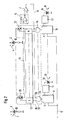
- Figure 1 shows the structure of a device according to the invention, in each of which a photodiode a current-voltage converter and a comparator are assigned.
- the photodiodes 1, 2 are in the reverse direction connected. When the light falls (3 and 4, symbolized by the arrows), a photodiode current flows, which is proportional to the intensity of the incident light 3, 4.
- the incident Light can be laser light and / or ambient light.
- the AC component of the photodiodes 1, 2 is preferably converted into Tensions in the method according to the invention and in the device according to the invention by means of current-voltage converters, one current-voltage converter each Photodiode is assigned.
- the respective Photodiode current of the photodiodes 1, 2 by means of a current-voltage converter 5, 6 in converted a voltage.
- the output of each current-voltage converter 5, 6 is with a Comparator 7, 8 connected.
- a comparator 7, 8 is assigned to a photodiode 1, 2.
- the N comparators 7, 8 serve the signal component, which is created by the laser light, from the background signal to distinguish.
- the comparator 7, 8 specifies a threshold value above which the signal voltage must lie in order to be recognized as a laser signal.
- flip-flops 9, 10 are preferred Storage elements used. These flip-flops 9, 10 can assume two states, the set state and the reset state. For example, there is the flip-flop 9, 10 in the present invention in the reset state (zero state), until a laser beam hits the associated photodiode 1, 2 and the resulting one Signal caused a switching of the flip-flop 9, 10 in the set state. The position of the incident laser beam is saved in this way.
- an associated flip-flop 9, 10 is reset from the reset state (zero state) switched to the set state, whereby the signal caused by laser light is stored becomes.
- Each flip-flop 9, 10 controls the current via an interface 11, 12 a light emitting diode 13, 14. If a flip-flop 9, 10 is in the zero state, then it flows no current to the associated light emitting diode 13, 14 and the light emitting diode 13, 14 lights up Not. If a flip-flop 9, 10 is in the set state, a current flows to it associated LED 13, 14 and it emits light 15, 16 (symbolized by arrows).
- each memory element is erased regularly by setting it to zero the flip-flop 9, 10, that is, a setting in the reset state. All N flip-flops 9, 10 are regularly and at the same time by a signal in the reset state switched, the signal via a line 17 each having an input of the flip-flops 9, 10 reached. This clears the memory elements.
- Figure 2 shows the structure of a device according to the invention with a multiplex arrangement.
- the device is a multiplex arrangement which is arranged downstream of the photodiodes 1, 2.
- the Multiplex arrangement for carrying out a multiplex method can, for example, be a Multiplexer, a line and a demultiplexer include.
- the line can go to Example the multiplexer with a current-voltage converter 5, 6, a comparator 7, 8 and connect the demultiplexer.
- FIG. 1 two of N photodiodes 1, 2 are shown in FIG.
- the photodiodes 1, 2 is followed by a multiplex arrangement 18, which is shown in dashed lines in FIG Box is located.
- the technology shown here is a time-division multiplex method.
- a single signal line 19 is used alternately for signal transmission for the N photodiodes 1, 2 unlocked. This is shown schematically in FIG. 2 by N switches 20, 21 shown.
- N switches 20, 21 shown With the help of a current-voltage converter 5, all are successively AC components of the photodiodes 1, 2 flowing through the single signal line 19, converted into tensions.
- a comparator 7 gives the threshold value for all photodiode signals in front and thus suppresses underground signals.
- a control unit 22 with N inputs and outputs and N digital serve for this purpose AND gate 23, 24.
- a flip-flop 9, 10 is only switched to the set state if both inputs of the associated AND gate have the state "1".
- On Input 25 of each AND gate is connected to an output of control unit 22.
- This input 25 of the AND gate 23 has the state "1" when the control unit 22nd reports that a signal line 19 at the second input 26 of the AND gate 23rd incoming signal of that photodiode 1 can be assigned to this AND gate 23 heard.
- the second input 26 of the AND gate has the state "1", if a signal conducted via line 19 is not suppressed by comparator 7 was interpreted as a laser signal. Both inputs 25, 26 of an AND gate accordingly have the state "1" when a signal from the associated photodiode 1 is assigned and the signal is not suppressed by the comparator 7.
- the rest the circuit shown in Figure 2 is similar to the circuit in Figure 1 (flip-flops 9, 10, interfaces 11, 12, LEDs 13, 14, line for the reset signal 17).
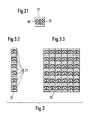
- Figure 3 shows possible arrangements of photo and light emitting diodes.
- Figure 3.1 is one Base cell 27 of the device according to the invention is shown.
- a base cell 27 contains a photodiode 28 and a light-emitting diode 29, which are side by side are arranged.
- the photodiode 28 and the light-emitting diode 29 can be optically opposite one another be isolated to avoid mutual interference.
- the light emitting diode 29 lights up when the photodiode 28 has detected laser radiation.
- the photodiodes 1, 2, 28 and the light emitting diodes 13, 14, 29 arranged on a line or a surface.
- the basic cells 27 are arranged on a straight line 30, in FIG. 3.3 on a surface 31.
- the base cells 27 can be in a straight line 30 with a Length of 100 mm or arranged on a square surface 31 of 100 mm x 100 mm his.
Landscapes
- Physics & Mathematics (AREA)
- Engineering & Computer Science (AREA)
- General Physics & Mathematics (AREA)
- Radar, Positioning & Navigation (AREA)
- Remote Sensing (AREA)
- Length Measuring Devices By Optical Means (AREA)
- Lasers (AREA)
Applications Claiming Priority (2)
| Application Number | Priority Date | Filing Date | Title |
|---|---|---|---|
| DE2001123756 DE10123756A1 (de) | 2001-05-16 | 2001-05-16 | Verfahren und Vorrichtung zum Sichtbarmachen einer Laserstrahlposition |
| DE10123756 | 2001-05-16 |
Publications (2)
| Publication Number | Publication Date |
|---|---|
| EP1258703A2 true EP1258703A2 (fr) | 2002-11-20 |
| EP1258703A3 EP1258703A3 (fr) | 2003-04-02 |
Family
ID=7684953
Family Applications (1)
| Application Number | Title | Priority Date | Filing Date |
|---|---|---|---|
| EP02008634A Withdrawn EP1258703A3 (fr) | 2001-05-16 | 2002-04-17 | Procédé et dispositif pour rendre visible la position d'un faisceau laser |
Country Status (2)
| Country | Link |
|---|---|
| EP (1) | EP1258703A3 (fr) |
| DE (1) | DE10123756A1 (fr) |
Cited By (2)
| Publication number | Priority date | Publication date | Assignee | Title |
|---|---|---|---|---|
| JP2017528202A (ja) * | 2014-08-19 | 2017-09-28 | コーニンクレッカ フィリップス エヌ ヴェKoninklijke Philips N.V. | X線イメージング装置 |
| EP3663710A4 (fr) * | 2017-08-04 | 2021-05-19 | Northwest Instrument Inc. | Ensemble de détecteur, détecteur et système de télémétrie laser |
Family Cites Families (13)
| Publication number | Priority date | Publication date | Assignee | Title |
|---|---|---|---|---|
| US3819273A (en) * | 1972-02-14 | 1974-06-25 | Laser Alignment | Light target and sensor |
| US3887012A (en) * | 1973-12-03 | 1975-06-03 | Caterpillar Tractor Co | Automatic levelling system for earth working blades and the like |
| US3972622A (en) * | 1974-09-19 | 1976-08-03 | New Hampshire Ball Bearings, Inc. | Electronic survey target |
| DE2756364C3 (de) * | 1977-12-17 | 1989-06-29 | Ruhrkohle Ag, 4300 Essen | Fotoelektrische Nivellierlatte |
| DE3506304C1 (de) * | 1985-02-22 | 1986-04-10 | Harms, Paul G., 6253 Hadamar | Optoelektronischer Messempfaenger und Verfahren zum Steuern des optoelektronischen Messempfaengers |
| DE3833153A1 (de) * | 1988-09-29 | 1990-04-05 | Ernst Wilhelm Mende | Verfahren zum erfassen des zentrums eines von einem nivelliergeraet (sog. baulaser) projizierten laserstrahls mittels mindestens zweier spiegelbildlich zu einer "null-linie" angeordneten laserlichempfindlichen signalgebenden empfangselementen, sowie vorrichtung zur durchfuehrung d. verfahrens |
| JP2743493B2 (ja) * | 1989-07-10 | 1998-04-22 | 株式会社ニコン | 受光位置検出装置 |
| JP3015059B2 (ja) * | 1989-12-20 | 2000-02-28 | 株式会社トプコン | 光検出方法およびそのための装置 |
| US5343033A (en) * | 1993-06-22 | 1994-08-30 | Apache Technology Inc. | Method and apparatus for detecting laser light having a plurality of pulse integrator and automatic gain control circuits |
| JP3670075B2 (ja) * | 1996-03-06 | 2005-07-13 | 株式会社トプコン | 適正高さ表示装置 |
| DE19634800A1 (de) * | 1996-08-29 | 1998-03-05 | Hilti Ag | Vorrichtung zum Anbringen von Markierungen an Flächen |
| DE19757461A1 (de) * | 1997-12-23 | 1999-06-24 | Hilti Ag | Baulaser |
| DE19902075A1 (de) * | 1999-01-20 | 2000-08-17 | Bosch Gmbh Robert | Markierwerkzeug |
-
2001
- 2001-05-16 DE DE2001123756 patent/DE10123756A1/de not_active Ceased
-
2002
- 2002-04-17 EP EP02008634A patent/EP1258703A3/fr not_active Withdrawn
Non-Patent Citations (1)
| Title |
|---|
| None * |
Cited By (2)
| Publication number | Priority date | Publication date | Assignee | Title |
|---|---|---|---|---|
| JP2017528202A (ja) * | 2014-08-19 | 2017-09-28 | コーニンクレッカ フィリップス エヌ ヴェKoninklijke Philips N.V. | X線イメージング装置 |
| EP3663710A4 (fr) * | 2017-08-04 | 2021-05-19 | Northwest Instrument Inc. | Ensemble de détecteur, détecteur et système de télémétrie laser |
Also Published As
| Publication number | Publication date |
|---|---|
| EP1258703A3 (fr) | 2003-04-02 |
| DE10123756A1 (de) | 2002-12-05 |
Similar Documents
| Publication | Publication Date | Title |
|---|---|---|
| DE69309226T3 (de) | Lichtvorhang mit Anzeigern für einzelne Lichtstrahlen und Betriebsverfahren | |
| DE2952106C2 (de) | Lichtelektrische inkrementale Längen- oder Winkelmeßeinrichtung | |
| DE3743180C2 (fr) | ||
| DE2948854C2 (fr) | ||
| DE3104972C2 (de) | Lichtelektrische inkrementale Positioniereinrichtung | |
| EP0892280B1 (fr) | Procédé pour faire fonctionner un dispositif capteur opto-électronique | |
| EP2638359B1 (fr) | Système à laser pour la construction, constitué d'un laser rotatif et d'un récepteur de laser et procédé associé | |
| EP0049764B1 (fr) | Dispositif de mesure incrémental des longueurs ou des angles | |
| DE2922471A1 (de) | Passanten-zaehlvorrichtung | |
| WO2003009476A1 (fr) | Dispositif optoelectronique de detection de position et de mouvement et procede correspondant | |
| DE3512708C1 (de) | Optoelektronische Messlatte | |
| DE2850117A1 (de) | Daten-eingabetablett-steuerung | |
| DE3511330A1 (de) | Anordnung zum eingeben von grafischen mustern | |
| EP0395844B1 (fr) | Dispositif de mesure de position à points de repère | |
| DE1905392A1 (de) | Vorrichtung zum Erzeugen von elektrischen Signalen mittels eines Skalengitters,das relativ zu einem Indexgitter bewegbar ist | |
| AT518369B1 (de) | Verfahren und ICT-Einrichtung zum Überprüfen von zumindest zwei LEDs enthaltenden Modulen einer Beleuchtungseinrichtung | |
| DE3924951C2 (fr) | ||
| EP2926087A1 (fr) | Objet cible pour un appareil de mesure à laser et procédé pour l'identification de l'objet cible | |
| DE3625643A1 (de) | Ortsaufloesender sensor zur erfassung einzelner lichtblitze | |
| EP1258703A2 (fr) | Procédé et dispositif pour rendre visible la position d'un faisceau laser | |
| DE3248911C2 (de) | Informationsgerät für den Fahrgastraum öffentlicher Verkehrsmittel | |
| EP0370009B1 (fr) | Salle de controle | |
| DE69012556T3 (de) | Flugzeugpark- und informationssystem. | |
| DE4308456A1 (de) | Vorrichtung zur Lagebestimmung eines Positionierkörpers relativ zu einem Bezugskörper | |
| DE10064534A1 (de) | Anzeigevorrichtung für Fassaden-Displays |
Legal Events
| Date | Code | Title | Description |
|---|---|---|---|
| PUAI | Public reference made under article 153(3) epc to a published international application that has entered the european phase |
Free format text: ORIGINAL CODE: 0009012 |
|
| AK | Designated contracting states |
Kind code of ref document: A2 Designated state(s): AT BE CH CY DE DK ES FI FR GB GR IE IT LI LU MC NL PT SE TR |
|
| AX | Request for extension of the european patent |
Free format text: AL;LT;LV;MK;RO;SI |
|
| PUAL | Search report despatched |
Free format text: ORIGINAL CODE: 0009013 |
|
| AK | Designated contracting states |
Kind code of ref document: A3 Designated state(s): AT BE CH CY DE DK ES FI FR GB GR IE IT LI LU MC NL PT SE TR Designated state(s): AT BE CH CY DE DK ES FI FR GB GR IE IT LI LU MC NL PT SE TR |
|
| AX | Request for extension of the european patent |
Extension state: AL LT LV MK RO SI |
|
| 17P | Request for examination filed |
Effective date: 20031002 |
|
| AKX | Designation fees paid |
Designated state(s): CH DE FR GB IT LI |
|
| 17Q | First examination report despatched |
Effective date: 20061115 |
|
| STAA | Information on the status of an ep patent application or granted ep patent |
Free format text: STATUS: THE APPLICATION IS DEEMED TO BE WITHDRAWN |
|
| 18D | Application deemed to be withdrawn |
Effective date: 20070526 |