EP1258763A2 - Couches gonflantes dans du gel sur fibres, rubans de fibres et tubes de protection - Google Patents
Couches gonflantes dans du gel sur fibres, rubans de fibres et tubes de protection Download PDFInfo
- Publication number
- EP1258763A2 EP1258763A2 EP02290923A EP02290923A EP1258763A2 EP 1258763 A2 EP1258763 A2 EP 1258763A2 EP 02290923 A EP02290923 A EP 02290923A EP 02290923 A EP02290923 A EP 02290923A EP 1258763 A2 EP1258763 A2 EP 1258763A2
- Authority
- EP
- European Patent Office
- Prior art keywords
- gel
- fiber optic
- swellable
- optic cable
- cable according
- Prior art date
- Legal status (The legal status is an assumption and is not a legal conclusion. Google has not performed a legal analysis and makes no representation as to the accuracy of the status listed.)
- Withdrawn
Links
- 239000000835 fiber Substances 0.000 title claims abstract description 120
- XLYOFNOQVPJJNP-UHFFFAOYSA-N water Substances O XLYOFNOQVPJJNP-UHFFFAOYSA-N 0.000 claims abstract description 9
- 239000000463 material Substances 0.000 claims description 47
- 239000013307 optical fiber Substances 0.000 claims description 18
- 229920000098 polyolefin Polymers 0.000 claims description 14
- 229920001577 copolymer Polymers 0.000 claims description 8
- 229920001897 terpolymer Polymers 0.000 claims description 6
- 230000008961 swelling Effects 0.000 abstract description 11
- 238000001125 extrusion Methods 0.000 abstract description 4
- 238000000034 method Methods 0.000 abstract description 4
- 239000002245 particle Substances 0.000 abstract description 4
- 238000000926 separation method Methods 0.000 abstract description 4
- 238000003848 UV Light-Curing Methods 0.000 abstract description 3
- 238000013007 heat curing Methods 0.000 abstract description 3
- 238000010521 absorption reaction Methods 0.000 abstract description 2
- 230000015556 catabolic process Effects 0.000 abstract description 2
- 230000002522 swelling effect Effects 0.000 abstract description 2
- 230000000930 thermomechanical effect Effects 0.000 abstract description 2
- 230000007704 transition Effects 0.000 abstract description 2
- 238000005452 bending Methods 0.000 abstract 1
- 230000001050 lubricating effect Effects 0.000 abstract 1
- 239000000499 gel Substances 0.000 description 62
- 239000010410 layer Substances 0.000 description 53
- 150000001875 compounds Chemical class 0.000 description 9
- 230000001681 protective effect Effects 0.000 description 9
- -1 Polyethylene Polymers 0.000 description 6
- 238000000576 coating method Methods 0.000 description 6
- 239000003921 oil Substances 0.000 description 6
- 239000004698 Polyethylene Substances 0.000 description 5
- 230000000694 effects Effects 0.000 description 5
- 239000011248 coating agent Substances 0.000 description 4
- 229920000573 polyethylene Polymers 0.000 description 4
- 239000004743 Polypropylene Substances 0.000 description 3
- 238000011049 filling Methods 0.000 description 3
- 230000003287 optical effect Effects 0.000 description 3
- PPBRXRYQALVLMV-UHFFFAOYSA-N Styrene Natural products C=CC1=CC=CC=C1 PPBRXRYQALVLMV-UHFFFAOYSA-N 0.000 description 2
- 230000007423 decrease Effects 0.000 description 2
- 239000002355 dual-layer Substances 0.000 description 2
- BXOUVIIITJXIKB-UHFFFAOYSA-N ethene;styrene Chemical compound C=C.C=CC1=CC=CC=C1 BXOUVIIITJXIKB-UHFFFAOYSA-N 0.000 description 2
- 239000011159 matrix material Substances 0.000 description 2
- 229920001155 polypropylene Polymers 0.000 description 2
- 238000012360 testing method Methods 0.000 description 2
- 230000002411 adverse Effects 0.000 description 1
- 230000003247 decreasing effect Effects 0.000 description 1
- 238000000151 deposition Methods 0.000 description 1
- 230000001066 destructive effect Effects 0.000 description 1
- 235000004879 dioscorea Nutrition 0.000 description 1
- 239000003814 drug Substances 0.000 description 1
- 238000005516 engineering process Methods 0.000 description 1
- 230000007613 environmental effect Effects 0.000 description 1
- 239000000945 filler Substances 0.000 description 1
- 238000007667 floating Methods 0.000 description 1
- 238000009472 formulation Methods 0.000 description 1
- 229910021485 fumed silica Inorganic materials 0.000 description 1
- 239000011521 glass Substances 0.000 description 1
- 239000003365 glass fiber Substances 0.000 description 1
- 230000005484 gravity Effects 0.000 description 1
- 238000009434 installation Methods 0.000 description 1
- 230000003993 interaction Effects 0.000 description 1
- 238000011068 loading method Methods 0.000 description 1
- 229920001684 low density polyethylene Polymers 0.000 description 1
- 239000004702 low-density polyethylene Substances 0.000 description 1
- 238000005461 lubrication Methods 0.000 description 1
- 239000002480 mineral oil Substances 0.000 description 1
- 239000000203 mixture Substances 0.000 description 1
- 239000003607 modifier Substances 0.000 description 1
- 238000005457 optimization Methods 0.000 description 1
- 229920005606 polypropylene copolymer Polymers 0.000 description 1
- 229920005653 propylene-ethylene copolymer Polymers 0.000 description 1
- 230000009467 reduction Effects 0.000 description 1
- 230000008439 repair process Effects 0.000 description 1
- 230000035939 shock Effects 0.000 description 1
- 238000003860 storage Methods 0.000 description 1
Images


Classifications
-
- G—PHYSICS
- G02—OPTICS
- G02B—OPTICAL ELEMENTS, SYSTEMS OR APPARATUS
- G02B6/00—Light guides; Structural details of arrangements comprising light guides and other optical elements, e.g. couplings
- G02B6/44—Mechanical structures for providing tensile strength and external protection for fibres, e.g. optical transmission cables
- G02B6/4401—Optical cables
- G02B6/4429—Means specially adapted for strengthening or protecting the cables
- G02B6/44384—Means specially adapted for strengthening or protecting the cables the means comprising water blocking or hydrophobic materials
-
- G—PHYSICS
- G02—OPTICS
- G02B—OPTICAL ELEMENTS, SYSTEMS OR APPARATUS
- G02B6/00—Light guides; Structural details of arrangements comprising light guides and other optical elements, e.g. couplings
- G02B6/44—Mechanical structures for providing tensile strength and external protection for fibres, e.g. optical transmission cables
- G02B6/4401—Optical cables
- G02B6/441—Optical cables built up from sub-bundles
- G02B6/4411—Matrix structure
Definitions
- the present invention generally relates to the field of optical fibers, in particular a fiber optical cable, ribbon, fiber or buffer tube having a gel-swellable layer for added protection and stability of the fibers in the cable structure.
- Optical fibers are very small diameter glass strands which are capable of transmitting an optical signal over great distances, at high speeds, and with relatively low signal loss as compared to standard wire or cable (including wire cable) networks.
- the use of optical fibers in today's technology has developed into many widespread areas, such as: medicine, aviation, communications, etc. Many of the areas of use for optical fibers, such as communications, require the optical fibers be protected from various destructive factors, such as adverse weather, moisture, impact damage, etc. This protection for the fibers can come in various ways.
- One common way to protect fibers, or fiber ribbons is to have a water resistant gel placed between the individual fibers, or fiber ribbons, and the cable buffer tubes, or the fiber ribbon stacks and the buffer tubes.
- This water resistant gel minimizes the amount of water or moisture that enters the fiber optic cable and protects the fibers from impact damage during installation, storage, repair, etc.
- An example of such a gel, along with its characteristics can be found in U.S. Patent No. 6,085,009 to Risch et al., which is incorporated herein by reference.
- One requirement for fiber optic cables is that the waterblocking gel within a fiberoptic cable does not exude out the end of the cable, even at elevated temperatures. Satisfactory resistance to flow of the waterblocking gel may be problematic especially for large diameter cables at high temperatures. Attenuation in individual fibers (loss of signal power in the fibers) may also be a problem in large cables containing fiber ribbons. In this case attenuation is generally attributable to microbending in the fibers, which tends to occur when the outer most fibers make contact with the walls of the buffer tubes or outer jackets. This is most common in the outer most fibers (corners) of ribbon stacks.
- One common test for determining whether or not a protective gel material is adequate is having the sample cable (with the gel compound) cut and vertically positioned in an oven. The temperature in the oven is then raised to approximately 70°C for a period of 24 hours. As the temperature of the compound or gel increases the viscosity and yield stress of the compound or gel decreases. When the viscosity and shear stress decreases, to a certain point, the gel or compound will drip or leak from the cut portion of the cable. This dripping or leaking is evidence that the particular gel or compound is not acceptable or the tube size is too large compared to a relatively small fiber bundle or ribbon stack for applications in fiber optic cables where such conditions may exist (i.e. higher temperatures)
- the compound or gel flow is governed by a number of different factors, such as: gravity, yield stress of the material, oil separation in the material, viscosity of the materials, coefficient of expansion of the material, adhesion or slippage of the material or compound to the walls of the buffer tube or outer jacket, and the diameter (cross-sectional area of the gel) of the cable.
- the present invention is directed to eliminating the above problems with using a protective gel or compound layer in fiber optic cables.
- the present invention addresses the problems recited above by adding a "gel-swellable" layer onto either the individual fibers or onto groupings of fibers, such as individual fiber or a stack of ribbons, or as a second layer for dual-layer gel-swellable buffer tubes.
- Materials such as swellable polyolefin or styrene copolymer are among some of the materials that can be used as the gel-swellable material on the fibers, ribbons, or for the dual-layer gel-swellable buffer tubes.
- the gel-swellable layers can be placed on the fibers or stacks by various methods, such as co-extrusion, and can be cured by either heat curing or UV curing.
- the gel-swellable layer adds a third layer on individual fibers, as it is deposited on top of the secondary coating, or adds a layer on top of the matrix material used to bind a ribbon or ribbon stack.
- the individually coated ribbons may be lubricated due to the swelling and thus slide with respect to each other in the stacks. This lubrication effect reduces stress under various thermo-mechanical loading conditions.
- the gel-swellable layers of this invention can be either smooth or textured (i.e. corrugated, longitudinal grooves, etc.).
- the gel-swellable layer absorbs some of the gel causing it to "swell".
- an initial concentration of gel may have increased concentration of oil to be absorbed by swelling coatings on the fibers, ribbons and inner surface of the tube.
- a certain volume of gel is absorbed by the layer, thus reducing the capability of the gel to flow at elevated temperatures.
- the swelled layers create a desirable stiffness transition from harder (less swelled) particles at the surface of the fiber to softer (more swelled) particles on the surface of the swelled layer.
- This variable-stiffness swelled layer then acts as a bumper and positioning structure between the fibers and the buffer tube or outer jacket, keeping the fibers in the center of the tube, and preventing gel flow at higher temperatures.
- the swelling action results in the absorption of the lower-viscosity components of the gel, thereby reducing the likelihood of oil separation in the gel, which leads to gel breakdown.
- the gel-swellable layer reduces the effective cross-section of the gel material in a tube or cable, which again aids the gel in reducing dripping and overall maintaining its stability to protect the optical fibers.
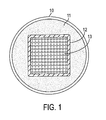
- a fiber optic cable is shown, where the cable (in the central-tube configuration) has an outer jacket 10, a ribbon stack 13, a protective gel 11 and a gel-swellable layer 12.
- the outer jacket 11 can be of any commonly used or known material, size and shape, and is not limited in any way by the present invention. Moreover the outer jacket 11 does not have to be the outer jacket of the cable, but can be one of many buffer tubes in a cable.
- the ribbon stack 13 can also be comprised of any number of individual ribbons or optical fibers. Any conventional or known ribbon stack configuration may be used with the present invention.
- the fibers do not have to be in a ribbon stack configuration, but can be wound in a helical pattern grouped as a fiber bundle, can be placed loosely or individually, or configured in any known or conventional manner within the tube 10.
- the configuration or positioning of the fibers or fiber ribbons 13 within the tube 10 is not critical to the present invention, although preferably the fiber should be approximately centered within the tube 10 to provide the maximum protection for the fibers on all sides of the tube 10.
- the gel material 11 can also be of any commonly known or used gel material. It is preferable that the gel material 11 provide moisture or water protection, as well as shock absorbing characteristics. Depending on the application of the fiber or cable the gel 11 should also have good viscosity characteristics at higher temperatures (above 70°C) to avoid having the gel lose its protective characteristics.
- An example of the gel that can be used can be found in U.S. Patent No. 6,085,009 to Risch et al., which is incorporated herein by reference.
- suitable gel formulations include gels comprised of mineral oils and/or synthetic polyolefin oils combined with a polymeric thixotropy modifier or pyrogenic silica. Further, gels such as commercially available Mastergel R-1806 and R-1806LT can be used.
- the gel-swellable layer 12 can be deposited on the ribbon stack 13 or the fibers by any commonly known or used method of depositing a layer onto such items, including co-extrusion. Further, the gel-swellable layer 12 can be cured by any commonly known or used method, such as heat or UV curing.
- the layer 12 can be either smooth or have an uneven shape, with ridges and valleys, channels, corrugation, etc. either running longitudinally along the length of the cable or concentrically. Further, it is not required that the layer 12 be continuous around the perimeter of the ribbon stack 13 or fibers, as shown in Figures 1-2B.
- the layer 12 can be made up of separate longitudinal strips running the length of the cable or fiber or may have a number of patches of gel-swellable material, which are placed along the length of the fiber or cable, but do not necessarily run the entire length of the cable or fiber. Moreover, although preferred, it is not necessary for the gel-swellable material to be placed or secured on the ribbon stack, or fiber, but it can be secured on the inside surface of the jacket or tube 10, or can be "floating" in the gel material between the jacket or tube 10 and the ribbon stack 13 or fibers. Further, it is possible to use more than one gel-swellable layer to optimize fiber performance.
- a polyolefin swellable type material is to be used for the gel-swellable material.
- the preferred density of the gel-swellable coating is less than 0.90 g/cc which would give a swelling interaction of greater than 10% at 85°C in polyolefin oilbased filling gels.
- Styrene copolymer materials can also be used as the layer 12.
- Another useful class of compounds for such an application that are highly swellable are ethylene-styrene interpolymers.
- a copolymer or terpolymer of polyethylene with a density of less than 0.90 g/cc is used as the gel swellable layer.
- any material which demonstrates any type of gel-swelling characteristics can be used, and the materials chosen for both the protective gel 11 and the gel-swellable layer 12 can be altered to optimize the protective characteristics of both the gel 11 and the gel-swellable layer 12.
- a desirable attribute to be achieved is to have the gel-swellable material absorb some of the lower-viscosity components of the protective gel, thereby reducing the likelihood of oil separation in the protective gel. Further, as the layer 12 absorbs some of the gel 11, the layer 12 should swell in size, growing larger and softer, therefore providing more protection for the fibers and effectively reducing the cross-section of the gel material, thus decreasing the tendency of the gel to flow at higher temperatures.
- the swellable layers of the present invention create soft bumpers or cushions for the fibers in the cables, and act as self-aligning members ensuring proper positioning of the stack 13 or fibers within the tube 10. It should be noted, however, that it is preferred to use materials for both the gel 11 and the gel-swellable layer 12 to optimize the above characteristics and advantages, but such optimization is not necessary for the present invention, and the characteristics desired may vary from application to application, depending on the intended use of the cable or fiber.
- Figure 3 depicts the swelling (% swelling on the vertical axis) of polyethylene as a function of temperature (Room Temperature, 60°C, and 85°C) and density
- Figure 4 depicts the effect of material type and density on swelling at 85°C, where PE is a polyethylene material and PP is a polypropylene material.
- the swellability of different material densities at 85°C can be anywhere from moderately swelled to totally miscible. It is desirable to have a gel-swellable material where the swellability varies as a function of temperature.
- the material chosen for the gel-swellable layer be softer than that used for the outer jacket or tube 10, which is normally a polypropylene copolymer type material, which typically has a density greater than 0.900 g/cc.
- swelling of the jacket materials at 85°C reaches a maximum value of less than 3% with a polyolefin oil based gel.
- a polyolefin oil based gel The characteristics of such a gel are discussed in U.S. Patent No. 6,085,009).
- both polethylenes and polypropylenes with a density below about 0.89 g/cc are substantially swellable with a polyolefin based gel. Therefore, when this type of material is used for the gel-swellable layer, the gel-swellable layer will absorb some of the gel while the buffer tube or jacket 10 would remain substantially unaffected.
- Examples of materials suitable for the gel filling materials include polyolefin oilbased filling gel. Overall the gel-swellable materials in the form of strings, coatings, etc. include ethylene-octene copolymers, propylene-ethylene copolymers, ethylene-octene-propylene terpolymers or other similar copolymers or terpolymers. Other suitable materials for such an application, which are highly swellable, are ethylene-styrene interpolymers. In the preferred embodiment, low-density polyethylene, with a density less than 0.90 g/cc is used as a gel-swellable layer on the fibers, ribbons and ribbon stacks.
- the further refinements of material selection and material combination can be accomplished to optimize the protective characteristics of both the gel and gel-swellable layer combination under various different potential environmental conditions. Further, it is contemplated that the performance of the present invention can be enhanced by the use of additional fillers, strings, or yams commonly known or used in the art, either placed in the gel material, or secured to the gel swellable layer to provide additional fiber or cable protection, and aid in maintaining the stability of the gel-swellable layer.
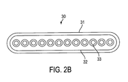
- Figures 2A and 2B show a typical optical fiber and fiber ribbon, respectively, with the gel-swellable layer of the present invention.
- Figure 2A shows a typical individual fiber 20 having the glass fiber 21, a primary coating 22, secondary coating 23, and a gel-swellable layer 24.
- Figure 2B shows a typical twelve fiber ribbon 30 having twelve fibers 33 positioned in a matrix material 32 and gel-swellable material layer 31.
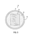
- Figure 5 shows yet another embodiment of the present invention, where a cable or buffer tube assembly 50 has the gel-swellable layer 52 secured or adhered to the inner surface of buffer tube or outer jacket 51 such that the gel 53 is positioned between the gel-swellable layer 52 and the ribbon stack 54.
- the gel-swellable inner layer of the buffer tube can be smooth, or have corrugated or any other topology to increase or reduce contact area engaged with gel and as sliding or contact surface with ribbons.
- the ribbon stack 54 can be replaced with loose fibers or a single fiber ribbon or any common fiber configuration.
- the gel-swellable layer 52 can be secured or adhered to the jacket or tube 51 by any acceptable or commonly used means, including co-extrusion with the tube 51.
- Figure 6 shows an alternate embodiment of the present invention as shown in Figure 5, where the gel-swellable layer 52 on the inner surface of the tube 50 is not smooth, but is corrugated or has longitudinally running grooves.
Landscapes
- Physics & Mathematics (AREA)
- General Physics & Mathematics (AREA)
- Optics & Photonics (AREA)
- Insulated Conductors (AREA)
- Light Guides In General And Applications Therefor (AREA)
- Laminated Bodies (AREA)
Applications Claiming Priority (2)
| Application Number | Priority Date | Filing Date | Title |
|---|---|---|---|
| US09/851,247 US6876799B2 (en) | 2001-05-09 | 2001-05-09 | Gel-swellable layers on fibers, fiber ribbons and buffer tubes |
| US851247 | 2001-05-09 |
Publications (2)
| Publication Number | Publication Date |
|---|---|
| EP1258763A2 true EP1258763A2 (fr) | 2002-11-20 |
| EP1258763A3 EP1258763A3 (fr) | 2004-12-08 |
Family
ID=25310333
Family Applications (1)
| Application Number | Title | Priority Date | Filing Date |
|---|---|---|---|
| EP02290923A Withdrawn EP1258763A3 (fr) | 2001-05-09 | 2002-04-12 | Couches gonflantes dans du gel sur fibres, rubans de fibres et tubes de protection |
Country Status (3)
| Country | Link |
|---|---|
| US (2) | US6876799B2 (fr) |
| EP (1) | EP1258763A3 (fr) |
| CN (1) | CN1238747C (fr) |
Families Citing this family (19)
| Publication number | Priority date | Publication date | Assignee | Title |
|---|---|---|---|---|
| US6876799B2 (en) * | 2001-05-09 | 2005-04-05 | Alcatel | Gel-swellable layers on fibers, fiber ribbons and buffer tubes |
| US6970629B2 (en) * | 2002-12-19 | 2005-11-29 | Corning Cable Systems Llc | Optical tube assembly having a dry insert and methods of making the same |
| US7471862B2 (en) | 2002-12-19 | 2008-12-30 | Corning Cable Systems, Llc | Dry fiber optic cables and assemblies |
| US7664354B2 (en) * | 2006-08-01 | 2010-02-16 | Nexans | System and method for loose tube tight buffer indoor/outdoor optical fiber cable |
| NL1034923C2 (nl) * | 2008-01-16 | 2009-07-20 | Draka Comteq Bv | Optische kabel. |
| US8401353B2 (en) * | 2008-09-12 | 2013-03-19 | Draka Comteq B.V. | Optical fiber cable assembly |
| US7970247B2 (en) * | 2008-09-12 | 2011-06-28 | Draka Comteq B.V. | Buffer tubes for mid-span storage |
| US7974507B2 (en) * | 2008-09-12 | 2011-07-05 | Draka Comteq, B.V. | High-fiber-density optical fiber cable |
| EP2172619A1 (fr) | 2008-10-03 | 2010-04-07 | Services Pétroliers Schlumberger | Ensemble de bande à fibres optiques |
| US8625945B1 (en) | 2009-05-13 | 2014-01-07 | Draka Comteq, B.V. | Low-shrink reduced-diameter dry buffer tubes |
| US8625944B1 (en) | 2009-05-13 | 2014-01-07 | Draka Comteq, B.V. | Low-shrink reduced-diameter buffer tubes |
| GB0919902D0 (en) * | 2009-11-13 | 2009-12-30 | Qinetiq Ltd | Improvements in fibre optic cables for distributed sensing |
| US9464883B2 (en) | 2013-06-23 | 2016-10-11 | Eric Swanson | Integrated optical coherence tomography systems and methods |
| US9683928B2 (en) | 2013-06-23 | 2017-06-20 | Eric Swanson | Integrated optical system and components utilizing tunable optical sources and coherent detection and phased array for imaging, ranging, sensing, communications and other applications |
| US10969571B2 (en) | 2016-05-30 | 2021-04-06 | Eric Swanson | Few-mode fiber endoscope |
| US20210055491A1 (en) * | 2018-03-29 | 2021-02-25 | Sterlite Technologies Limited | Micro sheath buffer tube with rollable ribbons |
| CN111482194B (zh) * | 2019-01-25 | 2021-05-14 | 中国石油化工股份有限公司 | 一种烷基化催化剂及其应用 |
| US11681093B2 (en) | 2020-05-04 | 2023-06-20 | Eric Swanson | Multicore fiber with distal motor |
| CN119244689B (zh) * | 2024-12-06 | 2025-03-25 | 长春工业大学 | 一种自加载内应力的两杆两索张拉超材料胞元结构 |
Citations (3)
| Publication number | Priority date | Publication date | Assignee | Title |
|---|---|---|---|---|
| EP0422573A2 (fr) | 1989-10-09 | 1991-04-17 | Sumitomo Electric Industries, Ltd. | Câble à fibres optiques résistant à l'eau |
| EP0510967A2 (fr) | 1991-04-26 | 1992-10-28 | AT&T Corp. | Cable à fibre optique |
| WO2001014922A1 (fr) | 1999-08-23 | 2001-03-01 | Pirelli Cavi E Sistemi S.P.A. | Cable a fibres optiques dote de composants possedant une compatibilite amelioree avec les compositions de remplissage bloquant l'eau |
Family Cites Families (19)
| Publication number | Priority date | Publication date | Assignee | Title |
|---|---|---|---|---|
| US4645298A (en) | 1983-07-28 | 1987-02-24 | At&T Bell Laboratories | Optical fiber cable |
| EP0392265A3 (fr) | 1989-04-12 | 1991-02-06 | Siemens Aktiengesellschaft | Câble de communication optique |
| US5062685A (en) | 1989-10-11 | 1991-11-05 | Corning Incorporated | Coated optical fibers and cables and method |
| US5029974A (en) | 1990-01-22 | 1991-07-09 | Alcatel Na Cable Systems, Inc. | Unitube optical fiber cable |
| US5373578A (en) | 1993-12-21 | 1994-12-13 | At&T Corp. | Strippable coating for optical fiber |
| US5408561A (en) | 1994-03-23 | 1995-04-18 | Siecor Corporation | Flexible dielectric fiber optic drop cable |
| US5509097A (en) | 1994-04-07 | 1996-04-16 | Pirelli Cable Corporation | Optical fiber core and cable with reinforced buffer tube loosely enclosing optical fibers |
| CA2131219C (fr) | 1994-08-31 | 2003-01-28 | Tsuyoshi Nonaka | Fibre optique revetue |
| FR2725042B1 (fr) | 1994-09-26 | 1996-12-27 | Alcatel Cable | Cable a fibres optiques et dispositif de fabrication d'un tel cable |
| DE19516970A1 (de) | 1995-05-09 | 1996-11-14 | Siemens Ag | Kabel mit einer Füllmasse und Verfahren zu deren Herstellung |
| DE19517118A1 (de) | 1995-05-10 | 1996-11-14 | Siemens Ag | Langgestrecktes, optisches Übertragungselement |
| FR2760540B1 (fr) | 1997-03-10 | 1999-04-16 | Alsthom Cge Alcatel | Cable a fibres optiques serrees dans une gaine |
| US6085010A (en) | 1997-06-11 | 2000-07-04 | Dsm N.V. | Optical glass fiber ribbon assemblies and radiation-curable compositions for use in forming ribbon assemblies |
| US5911023A (en) | 1997-07-10 | 1999-06-08 | Alcatel Alsthom Compagnie Generale D'electricite | Polyolefin materials suitable for optical fiber cable components |
| US6146556A (en) * | 1998-04-29 | 2000-11-14 | Katoot; Mohammad W. | Polymer additives for forming objects |
| US6085009A (en) | 1998-05-12 | 2000-07-04 | Alcatel | Water blocking gels compatible with polyolefin optical fiber cable buffer tubes and cables made therewith |
| US6041153A (en) | 1998-07-01 | 2000-03-21 | Alcatel | Continuous composite reinforced buffer tubes for optical fiber cables |
| US6876799B2 (en) * | 2001-05-09 | 2005-04-05 | Alcatel | Gel-swellable layers on fibers, fiber ribbons and buffer tubes |
| US6859591B2 (en) * | 2001-12-12 | 2005-02-22 | Alcatel | Gel-swellable particles and yarns in gel-filled buffer tubes |
-
2001
- 2001-05-09 US US09/851,247 patent/US6876799B2/en not_active Expired - Fee Related
-
2002
- 2002-04-12 EP EP02290923A patent/EP1258763A3/fr not_active Withdrawn
- 2002-04-25 CN CN02118445.3A patent/CN1238747C/zh not_active Expired - Fee Related
-
2004
- 2004-12-29 US US11/023,387 patent/US6947648B2/en not_active Expired - Fee Related
Patent Citations (3)
| Publication number | Priority date | Publication date | Assignee | Title |
|---|---|---|---|---|
| EP0422573A2 (fr) | 1989-10-09 | 1991-04-17 | Sumitomo Electric Industries, Ltd. | Câble à fibres optiques résistant à l'eau |
| EP0510967A2 (fr) | 1991-04-26 | 1992-10-28 | AT&T Corp. | Cable à fibre optique |
| WO2001014922A1 (fr) | 1999-08-23 | 2001-03-01 | Pirelli Cavi E Sistemi S.P.A. | Cable a fibres optiques dote de composants possedant une compatibilite amelioree avec les compositions de remplissage bloquant l'eau |
Also Published As
| Publication number | Publication date |
|---|---|
| US6876799B2 (en) | 2005-04-05 |
| US6947648B2 (en) | 2005-09-20 |
| US20020168155A1 (en) | 2002-11-14 |
| US20050105863A1 (en) | 2005-05-19 |
| EP1258763A3 (fr) | 2004-12-08 |
| CN1238747C (zh) | 2006-01-25 |
| CN1384380A (zh) | 2002-12-11 |
Similar Documents
| Publication | Publication Date | Title |
|---|---|---|
| US6876799B2 (en) | Gel-swellable layers on fibers, fiber ribbons and buffer tubes | |
| US6714707B2 (en) | Optical cable housing an optical unit surrounded by a plurality of gel layers | |
| US7751666B2 (en) | Optical tube assembly having a dry insert and methods of making the same | |
| US7469087B2 (en) | Optical tube assembly having a dry insert and methods of making the same | |
| US9182566B2 (en) | Optical-fiber cable having a perforated water blocking element | |
| US7050688B2 (en) | Fiber optic articles, assemblies, and cables having optical waveguides | |
| US11656419B2 (en) | High density fiber optic ribbon cable | |
| US9279952B2 (en) | Water-blocked optical cable and process for the production thereof | |
| US5384880A (en) | Dielectric ribbon optical fiber cable | |
| US7936957B1 (en) | High-density fiber optic ribbon cable with enhanced water blocking performance | |
| US7336873B2 (en) | Optical tube assembly having a dry insert and methods of making the same | |
| US7646952B2 (en) | Optical fiber cable having raised coupling supports | |
| US5321788A (en) | Optical fiber cable which includes waterblocking and freeze preventing provisions | |
| US20040258372A1 (en) | Fiber optic cable having no rigid strength members and a reduced coefficient of thermal expansion | |
| US20050281517A1 (en) | Multi-layered buffer tube for optical fiber cable | |
| US8676011B1 (en) | Water blocked fiber optic cable | |
| US20110293230A1 (en) | Optical cable with dry core and dry buffer tubes | |
| WO2001084206A2 (fr) | Cable a fibres optiques | |
| US6618527B2 (en) | Fiber optic cables having grease layers with reduced agglomerate sizes | |
| KR200245859Y1 (ko) | 방수특성을 향상시킨 슬롯형 광케이블 |
Legal Events
| Date | Code | Title | Description |
|---|---|---|---|
| PUAI | Public reference made under article 153(3) epc to a published international application that has entered the european phase |
Free format text: ORIGINAL CODE: 0009012 |
|
| AK | Designated contracting states |
Kind code of ref document: A2 Designated state(s): AT BE CH CY DE DK ES FI FR GB GR IE IT LI LU MC NL PT SE TR |
|
| AX | Request for extension of the european patent |
Free format text: AL;LT;LV;MK;RO;SI |
|
| PUAL | Search report despatched |
Free format text: ORIGINAL CODE: 0009013 |
|
| AK | Designated contracting states |
Kind code of ref document: A3 Designated state(s): AT BE CH CY DE DK ES FI FR GB GR IE IT LI LU MC NL PT SE TR |
|
| AX | Request for extension of the european patent |
Extension state: AL LT LV MK RO SI |
|
| 17P | Request for examination filed |
Effective date: 20050324 |
|
| 17Q | First examination report despatched |
Effective date: 20050425 |
|
| AKX | Designation fees paid |
Designated state(s): AT BE CH CY DE DK ES FI FR GB GR IE IT LI LU MC NL PT SE TR |
|
| RAP1 | Party data changed (applicant data changed or rights of an application transferred) |
Owner name: DRAKA COMTEQ B.V. |
|
| 17Q | First examination report despatched |
Effective date: 20050425 |
|
| RAP1 | Party data changed (applicant data changed or rights of an application transferred) |
Owner name: DRAKA COMTEQ B.V. |
|
| RAP1 | Party data changed (applicant data changed or rights of an application transferred) |
Owner name: DRAKA COMTEQ B.V. |
|
| GRAP | Despatch of communication of intention to grant a patent |
Free format text: ORIGINAL CODE: EPIDOSNIGR1 |
|
| RTI1 | Title (correction) |
Free format text: OPTICAL FIBRE CABLE HAVING GEL-SWELLABLE LAYER |
|
| STAA | Information on the status of an ep patent application or granted ep patent |
Free format text: STATUS: THE APPLICATION IS DEEMED TO BE WITHDRAWN |
|
| 18D | Application deemed to be withdrawn |
Effective date: 20111101 |