EP1259862B1 - Dispositif de commande a manette de jeu et retroaction haptique - Google Patents
Dispositif de commande a manette de jeu et retroaction haptique Download PDFInfo
- Publication number
- EP1259862B1 EP1259862B1 EP01918220A EP01918220A EP1259862B1 EP 1259862 B1 EP1259862 B1 EP 1259862B1 EP 01918220 A EP01918220 A EP 01918220A EP 01918220 A EP01918220 A EP 01918220A EP 1259862 B1 EP1259862 B1 EP 1259862B1
- Authority
- EP
- European Patent Office
- Prior art keywords
- control handle
- gimbal
- axis
- joystick
- shaft
- Prior art date
- Legal status (The legal status is an assumption and is not a legal conclusion. Google has not performed a legal analysis and makes no representation as to the accuracy of the status listed.)
- Expired - Lifetime
Links
Images




Classifications
-
- G—PHYSICS
- G05—CONTROLLING; REGULATING
- G05G—CONTROL DEVICES OR SYSTEMS INSOFAR AS CHARACTERISED BY MECHANICAL FEATURES ONLY
- G05G25/00—Other details or appurtenances of control mechanisms, e.g. supporting intermediate members elastically
- G05G25/04—Sealing against entry of dust, weather or the like
-
- G—PHYSICS
- G05—CONTROLLING; REGULATING
- G05G—CONTROL DEVICES OR SYSTEMS INSOFAR AS CHARACTERISED BY MECHANICAL FEATURES ONLY
- G05G9/00—Manually-actuated control mechanisms provided with one single controlling member co-operating with two or more controlled members, e.g. selectively, simultaneously
- G05G9/02—Manually-actuated control mechanisms provided with one single controlling member co-operating with two or more controlled members, e.g. selectively, simultaneously the controlling member being movable in different independent ways, movement in each individual way actuating one controlled member only
- G05G9/04—Manually-actuated control mechanisms provided with one single controlling member co-operating with two or more controlled members, e.g. selectively, simultaneously the controlling member being movable in different independent ways, movement in each individual way actuating one controlled member only in which movement in two or more ways can occur simultaneously
- G05G9/047—Manually-actuated control mechanisms provided with one single controlling member co-operating with two or more controlled members, e.g. selectively, simultaneously the controlling member being movable in different independent ways, movement in each individual way actuating one controlled member only in which movement in two or more ways can occur simultaneously the controlling member being movable by hand about orthogonal axes, e.g. joysticks
-
- G—PHYSICS
- G05—CONTROLLING; REGULATING
- G05G—CONTROL DEVICES OR SYSTEMS INSOFAR AS CHARACTERISED BY MECHANICAL FEATURES ONLY
- G05G9/00—Manually-actuated control mechanisms provided with one single controlling member co-operating with two or more controlled members, e.g. selectively, simultaneously
- G05G9/02—Manually-actuated control mechanisms provided with one single controlling member co-operating with two or more controlled members, e.g. selectively, simultaneously the controlling member being movable in different independent ways, movement in each individual way actuating one controlled member only
- G05G9/04—Manually-actuated control mechanisms provided with one single controlling member co-operating with two or more controlled members, e.g. selectively, simultaneously the controlling member being movable in different independent ways, movement in each individual way actuating one controlled member only in which movement in two or more ways can occur simultaneously
- G05G9/047—Manually-actuated control mechanisms provided with one single controlling member co-operating with two or more controlled members, e.g. selectively, simultaneously the controlling member being movable in different independent ways, movement in each individual way actuating one controlled member only in which movement in two or more ways can occur simultaneously the controlling member being movable by hand about orthogonal axes, e.g. joysticks
- G05G9/04785—Manually-actuated control mechanisms provided with one single controlling member co-operating with two or more controlled members, e.g. selectively, simultaneously the controlling member being movable in different independent ways, movement in each individual way actuating one controlled member only in which movement in two or more ways can occur simultaneously the controlling member being movable by hand about orthogonal axes, e.g. joysticks the controlling member being the operating part of a switch arrangement
- G05G9/04788—Manually-actuated control mechanisms provided with one single controlling member co-operating with two or more controlled members, e.g. selectively, simultaneously the controlling member being movable in different independent ways, movement in each individual way actuating one controlled member only in which movement in two or more ways can occur simultaneously the controlling member being movable by hand about orthogonal axes, e.g. joysticks the controlling member being the operating part of a switch arrangement comprising additional control elements
- G05G9/04792—Manually-actuated control mechanisms provided with one single controlling member co-operating with two or more controlled members, e.g. selectively, simultaneously the controlling member being movable in different independent ways, movement in each individual way actuating one controlled member only in which movement in two or more ways can occur simultaneously the controlling member being movable by hand about orthogonal axes, e.g. joysticks the controlling member being the operating part of a switch arrangement comprising additional control elements for rotary control around the axis of the controlling member
-
- G—PHYSICS
- G06—COMPUTING OR CALCULATING; COUNTING
- G06F—ELECTRIC DIGITAL DATA PROCESSING
- G06F3/00—Input arrangements for transferring data to be processed into a form capable of being handled by the computer; Output arrangements for transferring data from processing unit to output unit, e.g. interface arrangements
- G06F3/01—Input arrangements or combined input and output arrangements for interaction between user and computer
- G06F3/016—Input arrangements with force or tactile feedback as computer generated output to the user
-
- A—HUMAN NECESSITIES
- A63—SPORTS; GAMES; AMUSEMENTS
- A63F—CARD, BOARD, OR ROULETTE GAMES; INDOOR GAMES USING SMALL MOVING PLAYING BODIES; VIDEO GAMES; GAMES NOT OTHERWISE PROVIDED FOR
- A63F2300/00—Features of games using an electronically generated display having two or more dimensions, e.g. on a television screen, showing representations related to the game
- A63F2300/10—Features of games using an electronically generated display having two or more dimensions, e.g. on a television screen, showing representations related to the game characterized by input arrangements for converting player-generated signals into game device control signals
- A63F2300/1037—Features of games using an electronically generated display having two or more dimensions, e.g. on a television screen, showing representations related to the game characterized by input arrangements for converting player-generated signals into game device control signals being specially adapted for converting control signals received from the game device into a haptic signal, e.g. using force feedback
-
- G—PHYSICS
- G05—CONTROLLING; REGULATING
- G05G—CONTROL DEVICES OR SYSTEMS INSOFAR AS CHARACTERISED BY MECHANICAL FEATURES ONLY
- G05G9/00—Manually-actuated control mechanisms provided with one single controlling member co-operating with two or more controlled members, e.g. selectively, simultaneously
- G05G9/02—Manually-actuated control mechanisms provided with one single controlling member co-operating with two or more controlled members, e.g. selectively, simultaneously the controlling member being movable in different independent ways, movement in each individual way actuating one controlled member only
- G05G9/04—Manually-actuated control mechanisms provided with one single controlling member co-operating with two or more controlled members, e.g. selectively, simultaneously the controlling member being movable in different independent ways, movement in each individual way actuating one controlled member only in which movement in two or more ways can occur simultaneously
- G05G9/047—Manually-actuated control mechanisms provided with one single controlling member co-operating with two or more controlled members, e.g. selectively, simultaneously the controlling member being movable in different independent ways, movement in each individual way actuating one controlled member only in which movement in two or more ways can occur simultaneously the controlling member being movable by hand about orthogonal axes, e.g. joysticks
- G05G2009/04766—Manually-actuated control mechanisms provided with one single controlling member co-operating with two or more controlled members, e.g. selectively, simultaneously the controlling member being movable in different independent ways, movement in each individual way actuating one controlled member only in which movement in two or more ways can occur simultaneously the controlling member being movable by hand about orthogonal axes, e.g. joysticks providing feel, e.g. indexing means, means to create counterforce
-
- G—PHYSICS
- G05—CONTROLLING; REGULATING
- G05G—CONTROL DEVICES OR SYSTEMS INSOFAR AS CHARACTERISED BY MECHANICAL FEATURES ONLY
- G05G9/00—Manually-actuated control mechanisms provided with one single controlling member co-operating with two or more controlled members, e.g. selectively, simultaneously
- G05G9/02—Manually-actuated control mechanisms provided with one single controlling member co-operating with two or more controlled members, e.g. selectively, simultaneously the controlling member being movable in different independent ways, movement in each individual way actuating one controlled member only
- G05G9/04—Manually-actuated control mechanisms provided with one single controlling member co-operating with two or more controlled members, e.g. selectively, simultaneously the controlling member being movable in different independent ways, movement in each individual way actuating one controlled member only in which movement in two or more ways can occur simultaneously
- G05G9/047—Manually-actuated control mechanisms provided with one single controlling member co-operating with two or more controlled members, e.g. selectively, simultaneously the controlling member being movable in different independent ways, movement in each individual way actuating one controlled member only in which movement in two or more ways can occur simultaneously the controlling member being movable by hand about orthogonal axes, e.g. joysticks
- G05G2009/04774—Manually-actuated control mechanisms provided with one single controlling member co-operating with two or more controlled members, e.g. selectively, simultaneously the controlling member being movable in different independent ways, movement in each individual way actuating one controlled member only in which movement in two or more ways can occur simultaneously the controlling member being movable by hand about orthogonal axes, e.g. joysticks with additional switches or sensors on the handle
-
- Y—GENERAL TAGGING OF NEW TECHNOLOGICAL DEVELOPMENTS; GENERAL TAGGING OF CROSS-SECTIONAL TECHNOLOGIES SPANNING OVER SEVERAL SECTIONS OF THE IPC; TECHNICAL SUBJECTS COVERED BY FORMER USPC CROSS-REFERENCE ART COLLECTIONS [XRACs] AND DIGESTS
- Y10—TECHNICAL SUBJECTS COVERED BY FORMER USPC
- Y10T—TECHNICAL SUBJECTS COVERED BY FORMER US CLASSIFICATION
- Y10T74/00—Machine element or mechanism
- Y10T74/20—Control lever and linkage systems
- Y10T74/20012—Multiple controlled elements
- Y10T74/20201—Control moves in two planes
Definitions
- the present invention generally concerns an input and control device, and more specifically, a control handle gimbal support mechanism for use in a joystick with haptic feedback, which is employed to produce control signals for controlling machinery, computer games, and the like.
- Joysticks are typically used to provide input control signals for controlling machinery and computer application programs, such as computer games.
- a typical joystick includes a control handle that is pivotally rotatable relative to a base in response to input forces applied by a user who is grasping the control handle. Movement of the control handle varies an output signal usually corresponding to the angular displacement of the control handle about orthogonal "X" and "Y" axes. It should be noted that movement of the joystick control handle is sometimes referred to in terms of its motion in the direction of planar X and Y axes, rather than a rotation about these axes.
- the output signal from a joystick is typically input to a receiving device, such as a computer, which processes the signal for controlling hardware or a computer software program.
- a receiving device such as a computer
- a forward or reverse movement of the joystick control handle about the X axis causes an output signal to be generated that is used to simulate control of the elevators of the aircraft and which thus affects the pitch of the aircraft in the simulation
- lateral movement of the joystick control handle about the Y axis produces a corresponding output signal that is used to control the ailerons of the simulated aircraft, and thus affects roll or rotation of the simulated aircraft about its longitudinal axis.
- Joysticks are generally designed to function either as on/off devices or as proportional devices.
- Lower cost joysticks operating as on/off devices only change the state of a positional switch to provide an indication of whether a minimum displacement of the control handle about one of the axes of the joystick has occurred, whereas proportional devices provide output signals having a magnitude varying proportionally with the extent of the displacement of the joystick control handle away from a known point, generally its "center" point.
- Higher performance software applications, such as flight simulators require the use of joysticks that provide proportional output signals.
- some joysticks provide an input signal corresponding to a third axis, which is commonly referred to as the "Z" axis.
- the Z axis generally extends longitudinally through the joystick control handle, and the Z-axis output signal typically is indicative of a rotational angular displacement of the joystick control handle about its longitudinally central axis.
- some joysticks are designed to provide force or tactile (“haptic”) feedback to the user.
- haptic force or tactile
- Such devices are often used with computer games, and the haptic feedback feature adds to the user experience.
- a haptic joystick can convey to the user the physical sensation of an object controlled by the user in a game or simulation colliding with a wall, moving through mud, driving over a bumpy road, etc. This haptic feedback makes the game or simulation more realistic and entertaining.
- a quarter gimbal mechanism typically includes a control handle shaft 12, to which a control handle (not shown) is fixedly or rotatably coupled.
- the control handle is pivotally coupled to an X-axis gimbal arm 14 by a pivot bearing 15 and is pivotally coupled to a Y-axis gimbal arm 16 by a pivot bearing 17.
- a cantilevered end 18 of X-axis gimbal arm 14 is pivotally mounted to a base member, e.g., a housing or frame (not shown), by a bearing mount 19 having a centerline 20 that is aligned with the "X" axis, while a cantilevered end 22 of Y-axis gimbal arm 16 is pivotally mounted to the base member by a similar bearing mount 23 having a centerline 24 aligned with the Y axis.
- a centerline 25 of pivot bearing 17 is substantially in coaxial alignment with centerline 20
- a centerline 26 of pivot bearing 15 is substantially in coaxial alignment with centerline 24.
- all of the centerlines are co-planar when the control handle shaft is in this configuration.
- a separate servo motor for each axis is operatively coupled to the joystick control handle via various mechanisms such that a desired force and/or velocity can be applied to the joystick control handle having a magnitude that is a function of the torque and/or velocity of the motor drive shaft.
- each servo motor is typically coupled to a respective gimbal arm through a transmission such as a gear train, so that the force generated at the joystick control handle is increased and the velocity is reduced.
- a transmission such as a gear train
- X-axis gimbal arm 14 is operatively coupled to a servo motor 28 by a gear train 29 that includes a pinion gear 30, a combination gear drive 32, and a drive gear 34.
- Drive gear 34 is mounted on a drive shaft 36 that is fixedly coupled to X-axis gimbal arm 14.
- Y-axis gimbal arm 16 is operatively coupled to a servo motor 38 by a gear train 39 that includes a pinion gear 40, a combination gear drive 42, and a drive gear 44 mounted on a drive shaft 46, which is fixedly coupled to Y-axis gimbal arm 16.
- the position of the joystick control handle needs to be determined. This function is generally performed by various electromechanical or optical position sensors that are operatively coupled to the joystick control handle. Examples of such sensors include rotary or linear potentiometers, optical encoders, and linear displacement voltage transducers (LDVTs).
- rotary or linear potentiometers In the exemplary quarter gimbal mechanism shown in FIGURE 1, an X-axis potentiometer 48 is coupled to drive shaft 36 via drive gear 34, and a Y-axis potentiometer 50 is coupled to drive shaft 46 via drive gear 44.
- Quarter gimbal 10 works in the following manner. It will be initially assumed that the servo motors are not powered and are free to rotate. In response to a user input force upon joystick control handle 12 in a forward direction F along the Y axis and perpendicular to the X axis, control handle shaft 12 pivots about pivot bearing 17, causing X-axis gimbal arm 14 to pivot about centerline 20 (i.e., about the X axis) in a counterclockwise direction. Since forward direction F is along the Y axis (and thus, aligned with centerline 24), there is no moment applied about centerline 24 to cause a rotation of Y-axis gimbal arm 16 about the Y axis.
- control handle shaft' 12 pivots about pivot bearing 15, causing Y-axis gimbal arm 16 to pivot about centerline 24 (i.e., about the Y axis) in a counterclockwise direction. Since direction L is along the X axis (and thus, aligned with centerline 20), there is no moment applied about centerline 20 to cause a rotation of X-axis gimbal arm 14 about the X axis.
- a control signal will be applied to each of servo motors 28 and 38 based on a sensed position of joystick control handle 12 and in accord with game criteria. For instance, a "rumble" effect can be applied to the joystick control handle by rapidly oscillating one or both of the servo motors to simulate the feel of a vehicle in the game rolling over bumpy terrain.
- Another common effect comprises applying a resistance to the joystick control handle that is proportional to the displacement of the control handle about an axis, such as to simulate the force that would be felt when a character in the game advances into an elastic medium. Under this effect, a command signal is generated to increase the torque of a given servo motor as a function of a displacement of the control handle about the axis corresponding to the given servo motor.
- each drive gear is drivingly coupled to a corresponding drive shaft using a keyway or spline to prevent the drive gear run spinning around the drive shaft.
- the loading on the keyway or spline teeth is substantial, so that the interface between the drive gear and drive shaft is a common point of failure. The frequency of these failures is increased due to the extreme level of vibration that often accompanies haptic feedback effects.
- each drive gear or drive member in the case of a transmission that employs belts or cables
- its respective gimbal that is substantially less susceptible to damage or failure caused by heavy loading and vibration.
- a haptic feedback joystick that primarily employs low-cost components and materials, yet provides performance that is as good as or better than more expensive devices.
- a joystick is provided with the features of claim 1, which joystick can be called a "haptic feedback joystick" and addresses many of the foregoing limitations in the prior art.
- signals are produced by the joystick for use in controlling a computer software program such as a computer game, in response to a pivotal displacement of a joystick control handle about two orthogonal axes.
- the joystick control handle is coupled to a multi-axis full-gimbal assembly, which is connected to electric motors that provide a haptic feedback force.
- the multi-axis full-gimbal assembly includes an upper and lower gimbal operatively coupled to a corresponding motor.
- the movement of the control handle about each axis is sensed by position sensors, which produce signals that are input to a computer running the software program.
- haptic feedback signals are generated and transmitted to the joystick and decoded by a motor controller.
- the motor controller produces appropriate electrical currents that energize the motors to produce the desired haptic feedback force effect applied to the control handle, which is experienced by a user gripping the control handle.
- the joystick also includes a third input axis (the "Z" axis), and rotation of the joystick control handle about the Z axis produces a third proportional output signal.
- Embodiments of the present invention are thus directed to a haptic feedback joystick that includes a control handle adapted to enable a user to apply an input force that pivotally displaces the control handle about the X, Y, and/or Z axis.
- the control handle is supported by a control handle shaft, which is coupled to a multiple axis, full-gimbal assembly that enables the control handle shaft (and thus the control handle) to be pivotally displaced about the X and Y axes.
- the full-gimbal assembly includes an upper gimbal having an opening through which the control handle shaft extends.
- Opposing ends of the upper gimbal are coupled to a frame so that the upper gimbal is rotatable about the Y axis, and is pivotally coupled to the control handle shaft so as to enable rotation of the control handle shaft about the X axis.
- a lower gimbal which preferably has substantially the same form as the upper gimbal, is also operatively coupled at opposing ends to the frame so as to be rotatable about the X axis and is pivotally coupled to the control handle shaft so as to enable rotation of the control handle shaft about the Y axis.
- Each of the upper and lower gimbals are coupled to a corresponding angular position sensor - each angular position sensor preferably comprising a potentiometer that senses the displacement of the control handle about one of the X and Y axes.
- Output signals indicative of the position of the control handle about these two axes are transmitted to a computer executing an application program.
- the computer generates haptic feedback signals corresponding to a desired haptic feedback force effect determined as a function of the control handle position and in accord with application program criteria.
- the haptic feedback signals are transmitted to a motion controller in the joystick that decodes the signals and produces appropriate electrical drive currents for the motors that are operatively coupled to the upper and lower gimbals, i.e., using a different motor for each gimbal.
- the motors When thus energized, the motors produce haptic feedback torques that are applied to the control handle, tending to cause it to rotate about the X and/or Y axes.
- the control handle shaft includes a lower portion having a first pair of support shafts extending in opposite directions along a common centerline that is generally aligned with the X axis.
- a second pair of support shafts, orthogonal to the first pair, also extend in opposite directions from the control handle shaft along a common centerline that is generally aligned with the Y axis.
- Each of the upper and lower gimbals comprises a yoke-shaped frame that includes a pair of bearings mounted on opposing sides of the frame.
- the upper gimbal bearings are adapted to rotatably support the X-axis support shafts and the lower gimbal bearings are adapted to rotatably support the Y-axis support shafts.
- control handle shaft preferably comprises an upper part and a lower part.
- the upper part includes a saddle from which the X-axis support shafts extend and in which a recess is defined.
- the Y-axis support shafts extend from the lower part.
- the lower part fits within the recess in the upper part enabling the lower and upper parts to be coupled together.
- Each motor is operatively coupled to a corresponding one of the upper and lower gimbals via a corresponding transmission.
- Each transmission includes an input member coupled to one of the motors and an output member coupled to the one of the upper and lower gimbals.
- the input member of each transmission includes a pinion gear coupled to one of the motors
- the output member comprises a sector gear operatively coupled to the pinion gear through a combination gear that is driven by the pinion gear.
- Each combination gear includes a large gear and a small gear mounted on a common rotational axis. The pinion gear engages the large gear, while the small gear engages the sector gear.
- each of the upper and lower gimbals includes a yoke-shaped frame having a pair of drive pins extending from a first end and having a shaft extending from a second end that is opposite the first end.
- the shaft of each yoke-shaped frame is received by a corresponding bearing mounted to the primary frame.
- Each of the transmissions includes a transmission bracket mounted to the primary frame that supports one of the motors.
- each transmission bracket includes a shaft extending from the bracket that is aligned with a different one of the X and Y axes, around which the sector gear rotates.
- Each transmission bracket also includes a pair of clearance slots through which the drive pins of a corresponding gimbal extend. The drive pins are received by holes defined in the sector gear so that the sector gear is fixedly coupled to the gimbal.
- a bearing support is thus provided for each end of both gimbals enabling the gimbals to rotate.
- control handle it is further preferable for the control handle to be rotatably mounted on the control handle shaft so as to enable rotation of the control handle about a longitudinal axis of the control handle shaft corresponding to a "Z" axis.
- a position sensor preferably a potentiometer, produces a signal indicative of the angular position of the control handle about the Z axis, as the control handle is rotated about this axis.
- a spring provides a bias force tending to return the control handle to a center position about the Z axis, if the joystick control handle is rotated away from the center position.
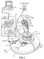
- a preferred embodiment of a joystick 110 in accord with the present invention enables a user to control three proportional input signals for a computer game by rotating or pivoting a control handle 112 about either of a pair of orthogonal axes, labeled "X" and “Y,” and/or by rotating control handle 112 about a third axis, labeled "Z,” which is coincident with a longitudinal axis of a control handle shaft 114.
- Joystick 110 is preferably connected to a Universal Serial Bus (USB) port 118 in a computer 116 through a USB cable 119.
- USB Universal Serial Bus
- the USB port provides a bi-directional communications link for the three proportional input signals and various control button input signals (as indicated by input signal data in a block 120) in regard to a computer game executing on computer 116.
- appropriate haptic control signals 122 are generated and transmitted to joystick 110 through the USB port.
- control handle 112 includes a left-half shell 123 and a right-half shell 124, each of which include a plurality of cylindrical bearing surfaces 125 that are adapted to rotatingly engage adjacent surfaces of control handle shaft 114 such that control handle 112 is supported by the control handle shaft, but can be rotated about the longitudinal axis of control handle shaft 114.
- This longitudinal axis defines the Z axis.
- a Z-axis potentiometer 126 is disposed within the control handle and is coupled to control handle shaft 114 such that the input shaft of the potentiometer is rotated relative to the potentiometer's body when the control handle is rotated about the Z axis. Accordingly, Z-axis potentiometer 126 controls a voltage of a signal output from the joystick so that the voltage is proportional to the extent of rotation of the control handle about the Z axis.
- control handle shaft 114 is pivotally coupled to a full-gimbal assembly 127, which includes an X-axis motor 128 and a Y-axis motor 129. These two motors apply haptic feedback torques acting on the control handle to rotate it about the X and Y axes, respectively, in response to haptic control signals 122.
- the full-gimbal assembly enables control handle shaft 114 to be pivoted about the X and Y axis, and further details of the full-gimbal mechanism are discussed below.
- Full-gimbal assembly 116 is disposed in a housing 132 that is connected to a base 133 by a plurality of fasteners 134.
- Base 133 includes a pair of motor supports 135 and 136, which are adapted to mate with the undersides of corresponding X- and Y-axis motors 128 and 129 (when assembled there will be 1 mm clearance between motor supports and the motors to keep the plastics away from the hot motors. The supports will prevent excessive movement of the motors.).
- a power supply/motor controller 137 that receives input power supplied from a conventional AC line outlet receptacle 138 through a power cable 140.
- the power supply/motor controller provides separate pulse width modulated electrical drive currents to selectively energize each of the X- and Y-axis motors 128 and 129.
- Full-gimbal assembly 127 also includes an X-axis potentiometer 130 and a Y-axis potentiometer 131 that control the magnitudes of the voltage of the output signals, so that they are proportional to the displacement of control handle shaft 114 about the X and Y axes, respectively.
- Housing 132 includes a generally square-shaped opening 142 (with chamfered corners) through which an upper portion of control handle shaft 114 extends.
- a lip 144 is formed along the perimeter of opening 142 and is shaped so as to define a spherical bearing surface that slidingly engages a spherical-shaped upper surface of a hemispherical collar 146, which is coupled to control handle shaft 114.
- hemispherical collar 146 slides against lip 144, thereby preventing debris from entering the full-gimbal assembly and preventing a user from injuring a finger that might otherwise be inserted through the opening.
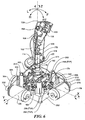
- joystick 110 is shown in a left rear-quarter view, relative to the perspective of a user of the joystick.
- moving control handle 112 in a forward direction "F” corresponds to a counterclockwise rotation of the control handle about the X axis (relative to the indicated view)
- moving the control handle in a reverse direction "R” corresponds to a clockwise rotation of the control handle about the X axis (relative to the indicated view).
- moving the control handle toward the right corresponds to a clockwise rotation of the control handle about the Y axis
- moving the control handle toward the left corresponds to a counterclockwise rotation about the Y axis
- Rotation of control handle 112 about the central longitudinal axis of control handle shaft 114 in either the clockwise or counterclockwise direction corresponds to the rotation of the control handle about the Z axis.
- joystick 110 In addition to the proportional input control signals provided by potentiometers 126, 130, and 131, joystick 110 also enables a user to provide an additional proportional input control signal through displacement of a throttle lever 148 that is pivotally mounted to base 133 and is coupled to a potentiometer (not shown) that produces an output signal indicative of the displacement of the throttle lever about a throttle axis T. Furthermore, "on/off"-type control signals are produced in response to a user actuating any of a plurality of control switches/buttons that are disposed on an upper portion of control handle 12, including a trigger switch 150, an 8-way point of view (POV) switch 152, and control buttons 154, 156, and 158.
- POV 8-way point of view
- the joystick also enables a user to selectively produce input signals by actuating any of a plurality of buttons 160 disposed on housing 132.
- Signal conditioning and processing of the proportional potentiometer signals and of the signals produced by the various buttons or controls on the joystick is carried out by electronic circuitry on a circuit board 161, which mounted to base 133.
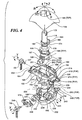
- control handle shaft 114 includes a slot 172 that is adapted to receive a tab (not shown) in a cap 173 (shown in FIGURE 6).
- Cap 173 is coupled to an input shaft of Z-axis potentiometer 126 so that the input shaft is turned with respect to the body of the potentiometer when control handle 112 is rotated relative to control handle shaft 114.
- Torsion spring 176 in which a torsion spring 176 is disposed is formed in a middle section of control handle shaft 114.
- Torsion spring 176 comprises a loop that encircles control handle shaft 114 and a pair of tangs 177 (only one of which is shown) that are nested within torsion spring housing 174 such that one of tangs 177 extends through a slot 178, while the other tang 177 extends through a slot 180 (shown in FIGURE 4).
- tangs 177 engage respective side walls 182 and 183 defined in torsion spring housing 174.
- control handle 112 is rotated about control handle shaft 114 in either direction away from a centered position, the end of one of tangs 177 is displaced away from an adjacent one of side walls 182 and 183, while the other tang 177 remains in contact with its adjacent side wall.
- a torque about the Z axis is produced by torsion spring 176 that opposes rotation of the control handle around the Z axis, away from the centered position of the control handle.
- a plurality of protrusions 184 and a shelf 186 couple control handle shaft 114 to hemispherical collar 146 and are formed in a lower portion of control handle shaft 114.
- a plurality of slots 189 are defined in hemispherical collar 146 so as to receive respective protrusions 184 to control input shaft 114, while shelf 186 controls the vertical position of hemispherical collar 146 relative to the control handle shaft.
- Control handle shaft 114 is able to freely pivot about the X axis with respect to upper gimbal frame 162.
- a pair of support shafts 188 and 190 extend from opposing sides of a saddle 187 disposed toward the bottom of the control handle shaft and share a common centerline that aligned with the X axis.
- Support shafts 188 and 190 are received by corresponding plain bearing 191 and 193, which are integrally formed in bearing bracket 192 and 194, respectively.
- the bearing brackets extend downwardly from upper gimbal frame 162 and are coupled to upper gimbal frame 162 by corresponding fasteners 196 and 198.
- upper gimbal frame 162 is formed as a yoke that includes an opening 201 through which an upper portion of control handle shaft 114 passes when the components are assembled.
- upper gimbal frame 162 comprises a plurality of cavities 202 separated by ribs 203 to reduce its weight and cost.
- a support shaft 204 that rotates within a plain bearing integrally formed in a bearing mount 164 extends from one end of upper gimbal frame 162, while a pair of drive pins 206 and 208 extend from a bracket 210 depending from an opposite end of the gimbal frame.
- Each of drive pins 206 and 208 includes a plurality of stiffeners 212 and a cylindrical portion 214 in which a threaded hole 216 (this hole is not threaded before the assembly.
- the screw is a thread forming screw and will form a thread during assembly) is defined.
- a stiffener 218 extends across bracket 210 to provide structural rigidity to the bracket and to drive pins 206, 208.
- Lower gimbal input shaft 166 comprises a cylindrical upper portion 222 that is mated with control handle shaft 114 upon assembly such that pivotal motion of the control handle shaft results in a corresponding motion of lower gimbal input shaft 166.
- both control handle shaft 114 and lower gimbal input shaft 166 are hollow so as to enable lead wires from Z-axis potentiometer 126, trigger switch 150, POV switch 152, and buttons 154, 156, and 158 to pass through and be routed to circuit board 161.
- Lower gimbal input shaft 166 also includes a pair of shafts 224 and 226 extending from opposing sides of a lower portion thereof and sharing a common centerline that is aligned with the Y axis that are pivotally mounted within respective bearing brackets 228 and 230. These bearing brackets are mounted on lower gimbal frame 168 using fasteners 232 and 234. It is noted that each of the upper and lower gimbal frames 162 and 168 preferably are of identical form such that the gimbal frames can be used interchangeably (In order for the upper and lower gimbal frames to be of identical form, the potentiometer 131 and 130 would need to be mounted differently because of the D shaft 247 and 246.
- lower gimbal frame 168 is yoke-shaped and is connected at opposing ends to a support shaft 238 and a bracket 240 from which a pair of drive pins 242 and 244 extend.
- Support shaft 238 is rotatably mounted within lower gimbal bearing mount 170 and includes a relief 245 comprising a foreshortened cylinder for receiving a similar flatted portion of an input shaft 246 of X-axis potentiometer 130 so as to couple the potentiometer's input shaft to lower gimbal frame 168.
- a similar relief is formed in support shaft 204 for receiving an input shaft 247 of Y-axis potentiometer 131 so as to couple the potentiometer's input shaft to upper gimbal frame 196.
- Drive pins 242 and 244 are of substantially identical form as drive pins 206 and 208 discussed above, and include a cylindrical portion 248 and threaded hole 250.
- full-gimbal assembly 127 in response to a pivotal displacement of control handle shaft 114 by a user will now be described, without considering any force applied by motors 128 and 129 and their corresponding transmission components.
- support shafts 188 and 190 pivot within respective bearing brackets 192 and 194.
- the pivot motion is solely about the X axis, which is coplanar with the Y axis and thus imparts no moment about the Y axis.
- control handle shaft 114 Due to coupling between control handle shaft 114 and lower gimbal input shaft 166, a moment is applied to lower gimbal frame 168 that results in support shaft 238 rotating within bearing mount 170, thereby causing lower gimbal frame 168 to rotate about the X axis.
- input shaft 246 of X-axis potentiometer 130 is rotated accordingly, enabling the extent of rotation of the control handle about the X axis to be detected through use of suitable signal conditioning and processing electronic circuitry disposed on circuit board 161. Details of the circuitry required for such signal conditioning and processing are well known by those of ordinary skill in the art, and accordingly, further details are not disclosed herein. Pivotal displacement of control handle shaft 114 in a reverse direction R results in a similar rotation about the X axis, except that this time, the rotation is in an opposite direction.
- a pivotal displacement of control handle shaft 114 in a left direction L and a right direction RT results in a similar rotation about the Y-axis, with no rotation about the X axis.
- a pivotal displacement of control handle shaft 114 toward left direction L causes a moment to be applied to upper gimbal frame 162, which results in rotation of support shaft 204 within bearing mount 164 about the Y axis in a clockwise direction.
- support shafts 224 and 226 of lower gimbal input shaft 166 are caused to pivot about the Y axis within their respective bearing brackets 228 and 230.
- control handle shaft 114 toward right direction RT produces a similar result, except that it is in a counterclockwise direction about the Y axis.
- control handle shaft 114 is common during game playing activities and simply produces a combination of the above described movements that is readily supported by the full-gimbal assembly.
- the configuration of the full-gimbal assembly is such that a maximal displacement of the control handle about both the X and Y axes can occur simultaneously, and so that a maximal displacement about one of the X and Y axes can be maintained while moving control handle 112 through a full range of motion about the other axis.
- full-gimbal assembly 127 provides haptic feedback forces in response to joystick control handle inputs and game criteria. In order to perform this function, it is necessary to be able to apply haptic feedback torques acting on control handle 112 about each of the X and Y axes. This function is accomplished by the motor and gear train described above for each axis. The motors are coupled to the frame of the full-gimbal assembly, as follows.
- full-gimbal assembly 127 is mounted to a frame 252 that is in turn attached to base 133 with a plurality of threaded fasteners (not shown).
- Frame 252 includes a plurality of threaded bosses 254 to which bearing mounts 164 and 170 are respectively mounted through use of corresponding pairs of fasteners 256.
- Frame 252 also includes four extended bosses 258 that are arranged at the corners of frame 252 and are adapted to receive corresponding tabs (not shown) that depend from housing 132.
- Each of lower and upper gimbal frames 162 and 168 are coupled to a corresponding motor and transmission that enables the gimbal frames to exert a feedback force upon control handle 112 about the gimbal axes in response to haptic feedback control signals.
- Y-axis motor 129 is mounted to a transmission bracket 260 by a pair of fasteners 262.
- Transmission bracket 260 includes a plurality of alignment holes 264 that are configured opposite corresponding threaded alignment pins 266 that are formed in frame 252 such that transmission bracket 260 can be secured to frame 252 by a plurality of fasteners 268.
- the transmission components include a pinion gear 270, a combination gear 272, and a sector gear 274.
- Pinion gear 270 is mounted on a shaft 276 that is coupled to the rotor of Y-axis motor 129.
- Combination gear 272 is rotatably mounted on a support shaft 278 and extends outwardly from transmission bracket 260.
- sector gear 274 is rotatably mounted on a support shaft 280 that extends outwardly from transmission bracket 260.
- Transmission bracket 260 further includes a pair of arcuate slots 282 through which drive pins 206 and 208 move freely as the control handle of the joystick pivots, and a pair of tabs 283 that limit the extend to the rotation of sector gear 274 in each direction.
- Sector gear 274 includes a pair of alignment holes 284 that receive cylindrical portions 214 of drive pins 206 and 208. Upon assembly, sector gear 274 is secured to upper gimbal frame 162 with a pair of fasteners 286 that are threaded into threaded holes 216 in drive pins 206 and 208. Stiffeners 212 define a backing surface, and sector gear 274 is sandwiched between this backing surface and the heads of fasteners 286 upon assembly, so that a rigid coupling exists between upper gimbal frame 164 and sector gear 274. As a result, upper gimbal frame 162 is provided with a gimbaled bearing support at each of its opposite ends, one of which is the bearing surface upon which the sector gear is mounted. Additionally, when control handle 114 is displaced about the Y axis through a given angle, sector gear 274 is caused to rotate through an equivalent angle.
- Combination gear 272 includes a large gear 286 and a small gear 288 that share a common axis. Small gear 288 extends from the central hub of the combination gear, and the large gear is the larger diameter portion of the combination gear.
- Combination gear 272 is secured to support shaft 278 by a snap ring retainer 290 and is prevented from moving forward toward transmission bracket 260 by sliding engagement with a ridge 292 formed in the periphery of sector gear 274.
- pinion gear 270 engages large gear 286, causing the combination gear to rotate.
- the gear teeth (not specifically shown) of small gear 288 engage plurality of gear teeth 294 of sector gear 274, causing sector gear 274 to rotate, thereby producing a torque about the Y axis that results in a haptic feedback force upon control handle 112 about the Y axis in the direction of the rotation of the sector gear. Movement of the control handle by the user about the Y axis produces a corresponding motion of the sector gear that is transmitted through the combination gear back to the pinion gear, causing the rotor of the Y-axis motor to rotate in corresponding fashion.
- the desired haptic feedback effect will require a torque to be applied to the control handle that causes no or little rotation of the sector gear, as would be the case if the desired effect was to simulate a user controlled object (in a game) bumping into a wall (in the game).
- the extent of the rotation of the Y-axis motor 129 rotor caused by the user moving the control handle is equal to the extent of rotation of the sector gear times the gear ratio of the transmission, which is approximately 18.3.
- the amount of torque produced by Y-axis motor 129 is equal to the gear ratio times the amount of torque produced at the motor's rotor.
- a motor and transmission of substantially identical form is provided to generate haptic feedback forces about the X axis.
- These include X-axis motor 128, a transmission bracket 300, a pinion gear 302, a combination gear 304 comprising a large gear 305 and a small gear 306, and a sector gear 308.
- Transmission bracket 300 which includes a plurality of alignment holes 310 is secured to frame 252 by a plurality of fasteners 312.
- Sector gear 308 which is rotatably mounted on a shaft 313 extending outwardly from transmission bracket 300, includes a pair of alignment holes 314 that are adapted to receive cylindrical portions 248 of drive pins 242 and 244.
- a pair of fasteners 315 are threaded into threaded holes 250 to secure sector gear 308 to drive pins 242 and 244. Additionally, drive pins 242 and 244 are enabled to pass through transmission bracket 300 by means of a pair of arcuate slots 316, and transmission bracket 300 includes a pair of tabs 317 for limiting the rotation of sector gear 308 in each direction.
- X-axis motor 128 is mounted to transmission bracket 300 with a pair of threaded fasteners 319.
- Combination gear 304 is rotatably mounted on a support shaft 318 that extends outwardly from transmission bracket 300 and is secured to support shaft 318 by a snap ring retainer 320.
- Pinion gear 302 which engages large gear 305 of combination gear 304, is mounted on a shaft 322 that is coupled to the rotor of X-axis motor 128.
- sector gear 308 engages small gear 306 of combination gear 304, while large gear 305 engages sector gear 308.
- a displacement of control handle shaft 114 about the X axis causes lower gimbal frame 168 to pivot about the X axis, causing sector gear 308 to rotate.
- This rotation causes combination gear 304 and pinion gear 302 to rotate, thereby rotating the rotor of X-axis motor 128.
- the extent of rotation of the rotor is equal to the extent of rotation of sector gear 308 times the gear ratio of the transmission. The converse is also true.
- the amount of torque applied at sector gear 308 by energizing X-axis motor 128 is equal to the amount of torque produced at the rotor of X-axis motor 128 times the gear ratio of the transmission.
- a desired haptic feedback force can also readily be applied to control handle 112 relative to the X axis.
- the components used in joystick 110 are preferred for high-volume injection molding of the parts, which is the preferred manufacturing technique for these components, although other types of plastic and other forming processes may alternatively be used.
- the components ideally suited for injection molding include upper and lower gimbal frames 162 and 168, bearing mounts 164 and 170, bearing brackets 192, 194, 228, and 230, control handle shaft 114, lower gimbal input shaft 166, hemispherical collar 146, upper housing 132, base 133, left-half shell 123, and right-half shell 124.
- Transmission brackets 260 and 300 are preferably fabricated of sheet metal using common metal forming techniques, such as stamping. It is further noted that where possible, many of the foregoing components have been designed to be of identical shape as corresponding other components. For example, the upper and lower gimbal frames, and corresponding bearing brackets and bearing mounts for the full-gimbal assembly are of identical shape. A particular advantage of the full-gimbal configuration of the present invention is that a single gimbal frame component can be suitable for use with either the upper or lower gimbals.
- each of the transmissions for the X and Y axes comprise a set of gears, including a sector gear, a combination gear, and a pinion gears. It is noted that other types of transmissions can alternatively be used, including transmissions that employ toothed drive belts and pulleys, cables and pulleys, or a combination of gears, drive belts and/or cables. Additionally, a full gear can be used in place of the sector gears, although sector gears are preferred in the embodiment discussed above because they provide a large gear radius without requiring the space of a conventional circular gear, and are lower in weight.
- appropriate servo motors that produce large torques at low speeds (through use of high-strength magnets and/or internal gear reduction) may be employed to eliminate the need for any transmission.
- the input shaft of the motor would be coupled to a drive member that is driven by a pair of drive pins extending from one end of the gimbal frame so as to couple the drive member (and thus the motor) to one of the upper and lower gimbal frames.
Landscapes
- Engineering & Computer Science (AREA)
- Physics & Mathematics (AREA)
- General Physics & Mathematics (AREA)
- Automation & Control Theory (AREA)
- General Engineering & Computer Science (AREA)
- Theoretical Computer Science (AREA)
- Human Computer Interaction (AREA)
- Mechanical Control Devices (AREA)
- Position Input By Displaying (AREA)
- User Interface Of Digital Computer (AREA)
- Switches With Compound Operations (AREA)
Claims (17)
- Manette de jeu comprenant :(a) une poignée de commande (112) adaptée pour permettre à un utilisateur d'appliquer une force qui déplace la poignée de commande (112) par pivotement;(b) un arbre de poignée de commande (114) s'étendant à partir de la poignée de commande (112) ;(c) un ensemble de cardans complet à axes multiples comprenant :(i) un boîtier principale (252) ;(ii) un cardan supérieur (162) comportant une ouverture (201) à travers laquelle l'arbre de poignée de commande (114) s'étend, ledit cardan supérieur (162) étant couplé fonctionnellement au niveau d'extrémités opposées audit boîtier principal (252) de façon à pouvoir tourner autour d'un premier axe (Y) et étant couplé de manière pivotante audit arbre de poignée de commande (114) de façon à permettre la rotation dudit arbre de poignée de commande (114) autour d'un second axe (X), ledit premier axe (Y) étant orthogonal au second axe (X) ; et(iii) un cardan inférieur (168) qui est couplé fonctionnellement au niveau d'extrémités opposées audit boîtier principal (252) de façon à pouvoir tourner autour du second axe (X) et qui est couplé de manière pivotante audit arbre de poignée de commande (114) de façon à permettre la rotation dudit arbre de poignée de commande (114) autour du premier axe (Y),(d) un premier capteur de position angulaire couplé fonctionnellement au cardan supérieur (162) de façon à détecter un déplacement pivotant de la poignée de commande (112) autour du premier axe (Y) ;(e) un second capteur de position angulaire couplé fonctionnellement au cardan inférieur (168) de façon à détecter un déplacement pivotant de la poignée de commande (112) autour du second axe (X) ;(f) un premier moteur (129) couplé fonctionnellement au cardan supérieur (162) et au boîtier principal (252) de façon à produire un couple agissant sur la poignée de commande (112) autour du premier axe en réponse à un premier courant d'attaque ; et(g) un second moteur (128) couplé fonctionnellement au cardan inférieur (168) et au boîtier principal (252) de façon à produire un couple agissant sur la poignée de commande (112) autour du second axe en réponse à un second courant d'attaque.
- Manette de jeu selon la revendication 1, comprenant en outre :(a) une première transmission comprenant un organe d'entrée couplé au premier moteur (129) et un organe de sortie couplé au cardan supérieur (162) ; et(b) une seconde transmission comprenant un organe d'entrée couplé au second moteur (128) et un organe de sortie couplé au cardan inférieur (168).
- Manette de jeu selon la revendication 2, caractérisée en ce que :(a) l'organe d'entrée de la première transmission comprend un premier engrenage à pignon (270) monté sur un arbre (276) s'étendant à partir du premier moteur (129) et tournant par entraînement à l'aide de ce dernier ;(b) l'organe de sortie de la première transmission comprend un premier engrenage d'entraînement, ladite première transmission comprenant en outre un premier grand engrenage (286) en alignement coaxial avec un premier petit engrenage (288) et couplé à ce dernier, ledit premier engrenage à pignon (270) étant engagé avec ledit premier grand engrenage (286) et ledit premier petit engrenage (288) étant engagé avec ledit premier engrenage d'entraînement ;(c) l'organe d'entrée de la seconde transmission comprend un second engrenage à pignon (302) monté sur un arbre (322) s'étendant à partir du second moteur (128) et tournant par entraînement à l'aide de ce dernier ; et(d) l'organe de sortie de la seconde transmission comprend un second engrenage d'entraînement, ladite seconde transmission comprenant en outre un second grand engrenage (305) en alignement coaxial avec un second petit engrenage (306) et couplé à ce dernier, ledit second engrenage à pignon (302) étant engagé avec ledit second grand engrenage (305) et ledit second petit engrenage (306) étant engagé avec ledit second engrenage d'entraînement.
- Manette de jeu selon la revendication 3, caractérisée en ce que le premier engrenage d'entraînement comprend un premier secteur denté (274), et le second engrenage d'entraînement comprend un second secteur denté (308).
- Manette de jeu selon au moins l'une des revendications précédentes, caractérisée en ce que chacun des cardans supérieur et inférieur (162, 168) comprend une armature en forme de fourche à partir de laquelle s'étend une paire de tiges d'entraînement (206, 208, 242, 244) au niveau d'une première extrémité et à partir de laquelle s'étend un arbre (204, 238) au niveau d'une deuxième extrémité en face de la première extrémité, ledit arbre (204, 238) étant reçu par un palier monté sur le boîtier principal (252), ledit manche à balai comprenant en outre :(a) un premier support de transmission (260), monté sur le boîtier principal (252), sur lequel le premier moteur (129) est monté et à partir duquel s'étend un arbre de maintien (278), en alignement coaxial avec ledit premier axe, sur lequel l'organe de sortie de la première transmission est monté de manière rotative, ledit premier support de transmission (260) comportant une paire d'ouvertures de dégagement (282), lesdites tiges d'entraînement (206, 208) du cardan supérieur (162) s'étendant à travers différentes ouvertures de la paire d'ouvertures de dégagement (282), lesdites tiges d'entraînement (206, 208) étant reçues par des réceptacles (284) correspondants définis dans ledit élément de sortie de la première transmission de sorte que ledit organe de sortie est couplé audit cardan supérieur (162) et que ledit cardan supérieur (162) est maintenu de manière rotative au niveau de ses première et seconde extrémités ; et(b) un second support de transmission (300), monté sur le boîtier principal (252), sur lequel le second moteur (128) est monté et à partir duquel s'étend un arbre de maintien (318), en alignement coaxial avec ledit second axe, sur lequel l'organe de sortie de la seconde transmission est monté de manière rotative, ledit second support de transmission (300) comportant une paire d'ouvertures de dégagement (316), lesdites tiges d'entraînement (242, 244) du cardan inférieur (168) s'étendant à travers différentes ouvertures de la paire d'ouvertures de dégagement (316) du second support de transmission (300), lesdites tiges d'entraînement (242, 244) étant reçues par des réceptacles (314) correspondants définis dans ledit organe de sortie de la seconde transmission de sorte que ledit organe de sortie est couplé audit cardan inférieur (168) et que ledit cardan inférieur (168) est maintenu de manière rotative au niveau de ses première et seconde extrémités.
- Manette de jeu selon la revendication 5, caractérisée en ce que l'organe de sortie de ladite première transmission comprend un premier secteur denté (274); ladite seconde transmission comprend un second secteur denté (308); et dans lequel s'étend une paire de languettes (283, 317) à partir de chacun des premier et second supports de transmission (260, 300), lesquelles sont configurées pour limiter la rotation en sens horaire et en sens anti-horaire de l'un des secteurs dentés respectifs parmi les premier et second secteurs dentés (274, 308).
- Manette de jeu selon au moins l'une des revendications précédentes, caractérisée en ce que le premier capteur de position angulaire comprend un premier potentiomètre (131) comportant un arbre d'entrée (247) qui est couplé au cardan supérieur (162) de façon à détecter une rotation du cardan supérieur (162) autour du premier axe, et le second capteur de position angulaire comprend un second potentiomètre (130) comportant un arbre d'entrée (246) qui est couplé au cardan inférieur (168) de façon à détecter une rotation du cardan inférieur (168) autour du second axe, les signaux de sortie produits par les premier et second potentiomètres (130, 131) variant en fonction de la rotation des cardans supérieur et inférieur (162, 168), respectivement.
- Manette de jeu selon au moins l'une des revendications précédentes, caractérisée en ce que chacun des cardans inférieur et supérieur (162, 168) comprend une armature en forme de fourche, et dans lequel l'arbre de poignée de commande (114) comporte une partie supérieure et une partie inférieure qui sont couplées ensemble, une paire d'arbres de maintien (188, 190) s'étendant à partir de ladite partie supérieure dans des directions opposées, lesquels arbres sont généralement alignés avec ledit second axe et reçus par des paliers respectifs (191, 193) montés sur les côtés opposés de l'armature en forme de fourche du cardan supérieur (162), et une paire d'arbres de maintien (224, 226) s'étendant à partir de ladite partie inférieure de l'arbre de poignée de commande dans des directions opposées, lesquels arbres sont généralement alignés avec ledit premier axe et reçus par des paliers respectifs (228, 230) montés sur les côtés opposés de l'armature en forme de fourche du cardan inférieur (168).
- Manette de jeu selon au moins l'une des revendications précédentes, caractérisée en ce que l'arbre de poignée de commande (114) comprend une partie supérieure et une partie inférieure, ladite partie supérieure comprenant une sellette (187) à partir de laquelle la première paire d'arbres de maintien (188, 190) s'étend et comprenant une partie en retrait qui y est définie, la seconde paire d'arbres de maintien (224, 226) s'étendant à partir de la partie inférieure, ladite partie inférieure étant reçue par la partie en retrait définie dans la partie supérieure de façon à coupler les parties inférieure et supérieure ensemble.
- Manette de jeu selon au moins l'une des revendications précédentes, caractérisée en ce que le cardan supérieur (162) et le cardan inférieur (168) ont sensiblement la même forme.
- Manette de jeu selon au moins l'une des revendications précédentes, caractérisée en ce que la poignée de commande (112) comprend au moins un commutateur d'entrée (150, 152, 154, 156, 158) adapté pour être actionné par un utilisateur et relié à au moins un fil de connexion, et dans lequel ledit fil de connexion s'étend à travers l'arbre de poignée de commande (114).
- Manette de jeu selon au moins l'une des revendications précédentes, caractérisée en ce que la poignée de commande (112) est montée à rotation sur l'arbre de poignée de commande (114) de façon à pouvoir tourner autour d'un axe longitudinal de l'arbre de poignée de commande (114), ledit manche comprenant en outre un troisième capteur (126) de position angulaire qui détecte la rotation de la poignée de commande (112) autour de l'axe longitudinal de l'arbre de poignée de commande (114).
- Manette de jeu selon au moins l'une des revendications précédentes, caractérisée en ce que l'arbre de poignée de commande (114) est couplé avec au moins l'un desdits cardans supérieur et inférieur (162, 168) de façon à empêcher la rotation de l'arbre de poignée de commande (114) autour de son axe longitudinal.
- Manette de jeu selon au moins l'une des revendications précédentes, comprenant en outre un ressort (176) qui est couplé fonctionnellement à la poignée de commande (112) et qui produit un couple de sollicitation s'opposant à la rotation de la poignée de commande (112) autour de l'axe longitudinal de l'arbre de poignée de commande (114), dans une direction s'éloignant d'une position centrale.
- Manette de jeu selon au moins l'une des revendications précédentes, comprenant en outre :(a) un élément hémisphérique (146) comportant une surface sphérique qui est couplé à l'arbre de poignée de commande (114); et(b) un logement (132), dans lequel l'ensemble de cardans complet à axes multiples (127) est disposé, comprenant une ouverture (142) à travers laquelle l'arbre de poignée de commande (114) s'étend, une surface d'appui adaptée pour s'engager de façon coulissante avec la surface sphérique de l'élément hémisphérique (146).
- Manette de jeu selon au moins l'une des revendications précédentes, comprenant en outre un contrôleur de mouvement (137) relié à une source d'énergie et fournissant les premier et second courants d'attaque auxdits premier et second moteurs (128, 129), respectivement, en réponse à un signal de commande de rétroaction haptique (122).
- Manette de jeu selon la revendication 16, caractérisée en ce que le contrôleur de mouvement (137) est approprié pour être relié de façon à communiquer avec un ordinateur hôte (116) sur lequel un jeu informatique est en cours d'exécution, ledit ordinateur (116) fournissant un signal de commande de rétroaction haptique (122) en réponse au jeu informatique de façon à créer une force de rétroaction haptique souhaitée qui est appliquée à la poignée de commande (112).
Applications Claiming Priority (3)
| Application Number | Priority Date | Filing Date | Title |
|---|---|---|---|
| US515558 | 1990-04-27 | ||
| US09/515,558 US6429849B1 (en) | 2000-02-29 | 2000-02-29 | Haptic feedback joystick |
| PCT/US2001/005857 WO2001065328A1 (fr) | 2000-02-29 | 2001-02-22 | Dispositif de commande a manette de jeu et retroaction haptique |
Publications (2)
| Publication Number | Publication Date |
|---|---|
| EP1259862A1 EP1259862A1 (fr) | 2002-11-27 |
| EP1259862B1 true EP1259862B1 (fr) | 2007-12-12 |
Family
ID=24051826
Family Applications (1)
| Application Number | Title | Priority Date | Filing Date |
|---|---|---|---|
| EP01918220A Expired - Lifetime EP1259862B1 (fr) | 2000-02-29 | 2001-02-22 | Dispositif de commande a manette de jeu et retroaction haptique |
Country Status (7)
| Country | Link |
|---|---|
| US (1) | US6429849B1 (fr) |
| EP (1) | EP1259862B1 (fr) |
| JP (1) | JP4165734B2 (fr) |
| AT (1) | ATE381049T1 (fr) |
| AU (1) | AU2001245321A1 (fr) |
| DE (1) | DE60131839T2 (fr) |
| WO (1) | WO2001065328A1 (fr) |
Cited By (2)
| Publication number | Priority date | Publication date | Assignee | Title |
|---|---|---|---|---|
| US9778743B2 (en) | 2013-04-22 | 2017-10-03 | Immersion Corporation | Gaming device having a haptic-enabled trigger |
| US10118688B2 (en) | 2015-08-18 | 2018-11-06 | Woodward, Inc. | Inherently balanced control stick |
Families Citing this family (165)
| Publication number | Priority date | Publication date | Assignee | Title |
|---|---|---|---|---|
| US6636197B1 (en) * | 1996-11-26 | 2003-10-21 | Immersion Corporation | Haptic feedback effects for control, knobs and other interface devices |
| DE19926784A1 (de) * | 1999-06-11 | 2000-12-14 | Wittenstein Gmbh & Co Kg | Vorrichtung zum Steuern einer Einrichtung |
| US7084854B1 (en) | 2000-09-28 | 2006-08-01 | Immersion Corporation | Actuator for providing tactile sensations and device for directional tactile sensations |
| JP2002202853A (ja) * | 2000-10-30 | 2002-07-19 | Sony Computer Entertainment Inc | 記録媒体、プログラム、方法、プログラム実行システムおよびプログラム実行装置 |
| US6892597B2 (en) * | 2001-07-27 | 2005-05-17 | Pelco | Joystick |
| US6624806B2 (en) * | 2001-08-27 | 2003-09-23 | Weistech Technology Co., Ltd. | Joystick capable of controlling direction rudder and accelerator synchronously |
| JP3934394B2 (ja) | 2001-10-30 | 2007-06-20 | アルプス電気株式会社 | ハプティック入力装置 |
| DE60214958T2 (de) * | 2001-11-22 | 2007-03-01 | Kabushiki Kaisha Tokai Rika Denki Seisakusho | Schaltvorrichtung |
| US6904823B2 (en) * | 2002-04-03 | 2005-06-14 | Immersion Corporation | Haptic shifting devices |
| US7369115B2 (en) | 2002-04-25 | 2008-05-06 | Immersion Corporation | Haptic devices having multiple operational modes including at least one resonant mode |
| AUPS304202A0 (en) * | 2002-06-19 | 2002-07-11 | Herbert, Robert James | Whole body computer game controller |
| US20040041787A1 (en) * | 2002-08-28 | 2004-03-04 | Graves Robert A. | Method and apparatus for a hybrid pointing device used with a data processing system |
| JP2004139845A (ja) * | 2002-10-17 | 2004-05-13 | Alps Electric Co Ltd | 力覚付与型入力装置 |
| JP3706365B2 (ja) * | 2002-12-10 | 2005-10-12 | 期美科技股▲ふん▼有限公司 | 直接駆動型動力ジョイスティック機構 |
| US6837124B2 (en) * | 2002-12-11 | 2005-01-04 | Tonic Fitness Technology, Inc. | Directly-driven power swing rod device without dead points |
| US7605802B2 (en) * | 2003-01-31 | 2009-10-20 | Volkswagen Aktiengesellschaft | Operator device with haptic feedback |
| US6920899B2 (en) * | 2003-03-27 | 2005-07-26 | Masco Corporation Of Indiana | Fluid control valve |
| US7032272B2 (en) | 2003-03-27 | 2006-04-25 | Masco Corporation Of Indiana | Friction hinge |
| US7148819B2 (en) * | 2003-05-04 | 2006-12-12 | Davis Kim | Directrometer |
| US7243746B1 (en) * | 2003-06-09 | 2007-07-17 | Abraham Vasant | Recreational electric vehicle |
| AU2004281370A1 (en) | 2003-08-29 | 2005-04-28 | Engineered Support Systems, Inc. | Electronically programmable actively damped sensor mount |
| US7204168B2 (en) * | 2004-02-25 | 2007-04-17 | The University Of Manitoba | Hand controller and wrist device |
| JP2005332039A (ja) * | 2004-05-18 | 2005-12-02 | Alps Electric Co Ltd | 力覚付与型入力装置 |
| JP2005332156A (ja) * | 2004-05-19 | 2005-12-02 | Alps Electric Co Ltd | 力覚付与型入力装置 |
| US7108012B2 (en) * | 2004-07-22 | 2006-09-19 | Masco Corporation Of Indiana | Fluid control valve |
| WO2006081198A2 (fr) * | 2005-01-25 | 2006-08-03 | The Board Of Trustees Of The University Of Illinois | Système compact haptique et de réalité virtuelle amplifiée |
| US20100312129A1 (en) | 2005-01-26 | 2010-12-09 | Schecter Stuart O | Cardiovascular haptic handle system |
| DE502006004481D1 (de) | 2005-04-22 | 2009-09-24 | Marquardt Gmbh | Elektrischer Schalter |
| DE102005019321A1 (de) * | 2005-04-26 | 2006-11-02 | Still Gmbh | Flurförderzeug mit einem Multifunktionshebel |
| US8089459B2 (en) * | 2005-06-06 | 2012-01-03 | Measurement Systems, Inc. | Manual control device including a magnetoresistive sensor element |
| JP4673695B2 (ja) * | 2005-07-29 | 2011-04-20 | 本田技研工業株式会社 | インターフェース装置 |
| FR2898205A1 (fr) * | 2006-03-01 | 2007-09-07 | Bosch Rexroth D S I Soc Par Ac | Telecommande d'engin mobile, en particulier engin de travaux publics, engin agricole ou de manutention |
| US7681340B2 (en) * | 2006-05-15 | 2010-03-23 | Monroe Truck Equipment, Inc. | Electronic control device |
| FR2902573B1 (fr) * | 2006-06-20 | 2008-09-05 | Dav Sa | Dispositif de commande electrique |
| US8545323B2 (en) * | 2006-06-30 | 2013-10-01 | Logitech Europe S.A. | Video game controller with compact and efficient force feedback mechanism |
| US8578966B2 (en) | 2006-07-28 | 2013-11-12 | Masco Corporation Of Indiana | Mixing valve |
| US7753074B2 (en) | 2006-07-28 | 2010-07-13 | Masco Corporation Of Indiana | Mixing valve |
| US8239032B2 (en) * | 2006-08-29 | 2012-08-07 | David Charles Dewhurst | Audiotactile vision substitution system |
| US7925039B1 (en) * | 2006-09-14 | 2011-04-12 | Griffin Technology, Inc. | Cylindrical controller for an electronic device |
| US7701161B2 (en) | 2006-10-02 | 2010-04-20 | Honeywell International Inc. | Motor balanced active user interface assembly |
| US7843426B2 (en) * | 2006-11-15 | 2010-11-30 | Honeywell International Inc. | Active human-machine interface system including interposed sector gears |
| JP2008200140A (ja) * | 2007-02-16 | 2008-09-04 | Taito Corp | 操作入力装置用プログラム及び操作入力装置 |
| DE102007012278A1 (de) * | 2007-03-09 | 2008-09-18 | CoActive Technologies, Inc., Greenwich | Joystick |
| US8581845B2 (en) * | 2007-09-14 | 2013-11-12 | International Business Machines Corporation | Hand activated input device with horizontal control surface |
| US8096206B2 (en) * | 2007-12-05 | 2012-01-17 | Liebherr-Aerospace Lindenberg Gmbh | Control device |
| US8212770B2 (en) * | 2008-02-11 | 2012-07-03 | Caterpillar Inc. | Joystick assembly for improved machine control |
| US9245453B1 (en) * | 2008-02-14 | 2016-01-26 | Doug Macalister | Flight simulator yoke |
| US8235723B2 (en) * | 2008-02-14 | 2012-08-07 | Doug Macalister | Flight simulator yoke |
| US8226479B2 (en) * | 2008-04-07 | 2012-07-24 | Disney Enterprises, Inc. | Group decision haptic feedback systems and methods |
| US20090266948A1 (en) * | 2008-04-29 | 2009-10-29 | Honeywell International Inc. | Human-machine interface two axis gimbal mechanism |
| US20090301249A1 (en) * | 2008-06-04 | 2009-12-10 | Timothy Smith | Automobile Gear Shifter Kit |
| US8087619B2 (en) * | 2008-07-30 | 2012-01-03 | Honeywell International, Inc. | Active control stick assembly including traction drive |
| US20100225585A1 (en) * | 2009-03-05 | 2010-09-09 | Research In Motion Limited | Method for navigating and selecting items with a return-to-center navigation component |
| DE102009015991A1 (de) * | 2009-04-02 | 2010-10-07 | Pi Ceramic Gmbh Keramische Technologien Und Bauelemente | Vorrichtung zur Erzeugung einer haptischen Rückmeldung einer tastenlosen Eingabeeinheit |
| US8487759B2 (en) | 2009-09-30 | 2013-07-16 | Apple Inc. | Self adapting haptic device |
| US8344914B2 (en) * | 2009-12-23 | 2013-01-01 | Tzu-Yuan Yeh | Intelligent multi-axial intuitive joystick suitable for use by both left-handers and right-handers |
| US10013058B2 (en) | 2010-09-21 | 2018-07-03 | Apple Inc. | Touch-based user interface with haptic feedback |
| DE102010047126A1 (de) * | 2010-10-04 | 2012-04-05 | Eppendorf Ag | Pipette |
| US20130198273A1 (en) | 2010-10-16 | 2013-08-01 | James Charles Vago | Methods, devices, and systems for video gaming |
| US10120446B2 (en) | 2010-11-19 | 2018-11-06 | Apple Inc. | Haptic input device |
| EP3043231A1 (fr) * | 2010-12-02 | 2016-07-13 | SeeScan, Inc. | Dispositif d'interface utilisateur détectée magnétiquement |
| JP5630559B2 (ja) * | 2011-02-28 | 2014-11-26 | 村田機械株式会社 | 上肢訓練装置 |
| JP5630560B2 (ja) * | 2011-02-28 | 2014-11-26 | 村田機械株式会社 | 上肢訓練装置 |
| US8942828B1 (en) | 2011-04-13 | 2015-01-27 | Stuart Schecter, LLC | Minimally invasive cardiovascular support system with true haptic coupling |
| US20120299829A1 (en) * | 2011-05-23 | 2012-11-29 | Cary Evans | Computer Input Device |
| WO2013040291A1 (fr) * | 2011-09-16 | 2013-03-21 | Rutgers, The State University Of New Jersey | Appareil de manipulation manuelle |
| US9946293B2 (en) * | 2011-12-12 | 2018-04-17 | Microsoft Technology Licensing, Llc | Magnetic force in a directional input device |
| CN103186163A (zh) * | 2011-12-27 | 2013-07-03 | 广明光电股份有限公司 | 力回馈装置 |
| US20130293362A1 (en) * | 2012-05-03 | 2013-11-07 | The Methodist Hospital Research Institute | Multi-degrees-of-freedom hand controller |
| US10013082B2 (en) | 2012-06-05 | 2018-07-03 | Stuart Schecter, LLC | Operating system with haptic interface for minimally invasive, hand-held surgical instrument |
| US9178509B2 (en) | 2012-09-28 | 2015-11-03 | Apple Inc. | Ultra low travel keyboard |
| US9122309B2 (en) * | 2012-11-13 | 2015-09-01 | Honeywell International Inc. | Active human-machine interface with force sensor overload protection |
| US9039531B2 (en) | 2013-02-05 | 2015-05-26 | Microsoft Technology Licensing, Llc | Rumble motor movement detection |
| JP6012498B2 (ja) * | 2013-02-14 | 2016-10-25 | アルプス電気株式会社 | 入力装置 |
| KR101397760B1 (ko) | 2013-02-21 | 2014-05-20 | 주식회사 티에이치아이 | 햅틱 디바이스 |
| JP6113598B2 (ja) * | 2013-07-22 | 2017-04-12 | 株式会社クボタ | 操作レバー |
| JP6114655B2 (ja) * | 2013-07-22 | 2017-04-12 | 株式会社クボタ | グリップ |
| JP6178146B2 (ja) * | 2013-07-22 | 2017-08-09 | 株式会社クボタ | グリップ |
| WO2015020663A1 (fr) | 2013-08-08 | 2015-02-12 | Honessa Development Laboratories Llc | Formes d'onde sculptées avec pas ou peu de réponse non provoquée |
| US9779592B1 (en) * | 2013-09-26 | 2017-10-03 | Apple Inc. | Geared haptic feedback element |
| HK1222728A1 (zh) | 2013-09-27 | 2017-07-07 | 苹果公司 | 具有觸覺致動器的帶體 |
| US9928950B2 (en) | 2013-09-27 | 2018-03-27 | Apple Inc. | Polarized magnetic actuators for haptic response |
| US10126817B2 (en) | 2013-09-29 | 2018-11-13 | Apple Inc. | Devices and methods for creating haptic effects |
| WO2015047372A1 (fr) | 2013-09-30 | 2015-04-02 | Pearl Capital Developments Llc | Actionneurs magnétiques pour réponse haptique |
| US9501084B1 (en) * | 2013-10-10 | 2016-11-22 | SD Technologies, LLC | Wearable electronic device with force feedback |
| US9317118B2 (en) | 2013-10-22 | 2016-04-19 | Apple Inc. | Touch surface for simulating materials |
| US9393493B2 (en) | 2013-11-12 | 2016-07-19 | Immersion Corporation | Gaming device with haptic effect isolated to user input elements |
| US10276001B2 (en) | 2013-12-10 | 2019-04-30 | Apple Inc. | Band attachment mechanism with haptic response |
| US9501912B1 (en) | 2014-01-27 | 2016-11-22 | Apple Inc. | Haptic feedback device with a rotating mass of variable eccentricity |
| JP6052214B2 (ja) * | 2014-03-24 | 2016-12-27 | マツダ株式会社 | 車両用シフト装置 |
| JP6052211B2 (ja) * | 2014-03-24 | 2016-12-27 | マツダ株式会社 | 車両用シフト装置 |
| DE102014105538A1 (de) * | 2014-04-17 | 2015-10-22 | Technische Universität Berlin | Haptisches System und Verfahren zum Betreiben |
| AU2014391723B2 (en) | 2014-04-21 | 2018-04-05 | Apple Inc. | Apportionment of forces for multi-touch input devices of electronic devices |
| GB201409409D0 (en) * | 2014-05-28 | 2014-07-09 | Bae Systems Plc | Inceptor apparatus |
| DE102015209639A1 (de) | 2014-06-03 | 2015-12-03 | Apple Inc. | Linearer Aktuator |
| US10316492B2 (en) | 2014-07-31 | 2019-06-11 | Cnh Industrial America Llc | Active force/vibration feedback control method and apparatus for a movable machine |
| US9830782B2 (en) | 2014-09-02 | 2017-11-28 | Apple Inc. | Haptic notifications |
| US10353467B2 (en) | 2015-03-06 | 2019-07-16 | Apple Inc. | Calibration of haptic devices |
| AU2016100399B4 (en) | 2015-04-17 | 2017-02-02 | Apple Inc. | Contracting and elongating materials for providing input and output for an electronic device |
| US9864397B2 (en) * | 2015-04-24 | 2018-01-09 | Nintendo Co., Ltd. | Multi-directional input device |
| DE102015017170B4 (de) | 2015-07-14 | 2023-03-02 | André Frank | System für die haptische Vermittlung von Fernsteuerbewegungen |
| DE102015213200C5 (de) | 2015-07-14 | 2022-08-25 | André Frank | Haptische Fernsteuerung |
| CN107925333B (zh) | 2015-09-08 | 2020-10-23 | 苹果公司 | 用于在电子设备中使用的线性致动器 |
| CN105160987B (zh) * | 2015-09-29 | 2017-09-15 | 哈尔滨莱特兄弟科技开发有限公司 | 一种模拟飞机转弯手轮操纵装置 |
| US9850957B2 (en) * | 2015-09-30 | 2017-12-26 | Apple Inc. | Electronic device with haptic actuation stiction release after non-movement threshold time period and related methods |
| FR3043475B1 (fr) * | 2015-11-06 | 2017-12-15 | Bosch Gmbh Robert | Telecommande d'engin |
| DE102015121017B4 (de) | 2015-12-03 | 2025-12-04 | Karl Storz Se & Co. Kg | Medizinische Beobachtungsvorrichtung mit einer Bedieneinheit sowie Verwendung eines Eingabemoduls |
| US9809955B2 (en) * | 2016-02-16 | 2017-11-07 | Caterpillar Inc. | Control device for an implement system |
| US10039080B2 (en) | 2016-03-04 | 2018-07-31 | Apple Inc. | Situationally-aware alerts |
| US10268272B2 (en) | 2016-03-31 | 2019-04-23 | Apple Inc. | Dampening mechanical modes of a haptic actuator using a delay |
| FR3051954B1 (fr) * | 2016-05-30 | 2021-04-02 | Bosch Gmbh Robert | Telecommande a manette equipee de moteurs generant une reaction appliquee a la manette |
| US10664002B2 (en) * | 2016-10-27 | 2020-05-26 | Fluidity Technologies Inc. | Multi-degrees-of-freedom hand held controller |
| US10331233B2 (en) | 2016-10-27 | 2019-06-25 | Fluidity Technologies, Inc. | Camera and sensor controls for remotely operated vehicles and virtual environments |
| US10331232B2 (en) | 2016-10-27 | 2019-06-25 | Fluidity Technologies, Inc. | Controller with situational awareness display |
| US10324487B2 (en) | 2016-10-27 | 2019-06-18 | Fluidity Technologies, Inc. | Multi-axis gimbal mounting for controller providing tactile feedback for the null command |
| US10520973B2 (en) | 2016-10-27 | 2019-12-31 | Fluidity Technologies, Inc. | Dynamically balanced multi-degrees-of-freedom hand controller |
| US10198086B2 (en) | 2016-10-27 | 2019-02-05 | Fluidity Technologies, Inc. | Dynamically balanced, multi-degrees-of-freedom hand controller |
| DE102016222231B3 (de) | 2016-11-11 | 2018-03-01 | André Frank | Haptische Fernsteuerung mit permanent erregtem Drehstromsynchronmotor |
| CN110088713B (zh) | 2016-12-14 | 2022-05-17 | 雷蛇(亚太)私人有限公司 | 输入设备 |
| US10707869B2 (en) * | 2017-05-18 | 2020-07-07 | Altec Industries, Inc. | Insulated joystick |
| JP7244985B2 (ja) * | 2017-05-19 | 2023-03-23 | 川崎重工業株式会社 | 操作装置及び操作システム |
| WO2018216780A1 (fr) * | 2017-05-24 | 2018-11-29 | 株式会社ミライセンス | Dispositif de transmission de stimulus |
| US10226697B2 (en) | 2017-06-01 | 2019-03-12 | Microsoft Technology Licensing, Llc | Input device with sector geared feedback trigger |
| US10384123B2 (en) | 2017-06-01 | 2019-08-20 | Microsoft Technology Licensing, Llc | Motor-driven adjustable-tension trigger |
| US10850190B2 (en) | 2017-06-01 | 2020-12-01 | Microsoft Technology Licensing, Llc | Input device with clutched force-feedback trigger |
| US10773159B2 (en) | 2017-06-01 | 2020-09-15 | Microsoft Technology Licensing, Llc | Input device with linear geared feedback trigger |
| US10737172B2 (en) | 2017-06-01 | 2020-08-11 | Microsoft Technology Licensing, Llc | Input device with force sensor feedback trigger |
| US10622538B2 (en) | 2017-07-18 | 2020-04-14 | Apple Inc. | Techniques for providing a haptic output and sensing a haptic input using a piezoelectric body |
| EP3701216A4 (fr) | 2017-10-27 | 2021-09-22 | Fluidity Technologies, Inc. | Monture à cardan à axes multiples pour dispositif de commande fournissant une rétroaction tactile pour la commande nulle |
| CN111566579A (zh) | 2017-10-27 | 2020-08-21 | 流体技术股份有限公司 | 用于远程操作的交通工具和虚拟环境的相机和传感器控件 |
| WO2019084506A1 (fr) | 2017-10-27 | 2019-05-02 | Fluidity Technologies, Inc. | Dispositif de commande équipé d'un dispositif d'affichage de connaissance de la situation |
| DE202018100806U1 (de) | 2018-02-14 | 2018-05-11 | André Frank | Haptische Fernsteuerung mit permanent erregtem Drehstromsynchronmotor |
| CN108407879B (zh) * | 2018-05-15 | 2023-12-12 | 北京美佳靓丽日用品有限公司 | 一种三维方向控制装置 |
| US10599223B1 (en) | 2018-09-28 | 2020-03-24 | Apple Inc. | Button providing force sensing and/or haptic output |
| US10691211B2 (en) | 2018-09-28 | 2020-06-23 | Apple Inc. | Button providing force sensing and/or haptic output |
| WO2020072043A1 (fr) * | 2018-10-02 | 2020-04-09 | Hewlett-Packard Development Company, L.P. | Contrôleurs de rétroaction pour dispositifs informatiques |
| WO2021038935A1 (fr) | 2019-08-28 | 2021-03-04 | アルプスアルパイン株式会社 | Dispositif de fonctionnement |
| WO2021038933A1 (fr) * | 2019-08-30 | 2021-03-04 | アルプスアルパイン株式会社 | Dispositif de manœuvre |
| US11380470B2 (en) | 2019-09-24 | 2022-07-05 | Apple Inc. | Methods to control force in reluctance actuators based on flux related parameters |
| WO2021090102A1 (fr) * | 2019-11-04 | 2021-05-14 | Indian Institute Of Science | Système de commande de manette de jeu |
| US11599107B2 (en) | 2019-12-09 | 2023-03-07 | Fluidity Technologies Inc. | Apparatus, methods and systems for remote or onboard control of flights |
| RU2727775C1 (ru) * | 2019-12-23 | 2020-07-23 | Денис Викторович Павленко | Контроллер для управления виртуальной бронетехникой |
| CN111359202B (zh) * | 2020-02-28 | 2023-12-26 | 歌尔科技有限公司 | 一种游戏手柄及其摇杆反馈力装置 |
| CN111346368A (zh) | 2020-02-28 | 2020-06-30 | 歌尔科技有限公司 | 一种游戏手柄及其摇杆反馈力装置 |
| CN111318011B (zh) * | 2020-02-28 | 2023-03-21 | 歌尔科技有限公司 | 一种游戏手柄及其摇杆反馈力装置 |
| CN113856193B (zh) * | 2020-06-30 | 2024-10-11 | 比亚迪股份有限公司 | 游戏手柄及车辆 |
| US12123168B2 (en) * | 2020-07-08 | 2024-10-22 | Manitou Equipment America, Llc | Offset control stick system and method |
| DE102020004344A1 (de) * | 2020-07-18 | 2022-01-20 | Kostal Automobil Elektrik Gmbh & Co. Kg | Elektrische Schalteinrichtung für ein Kraftfahrzeug |
| CN112490053B (zh) * | 2020-11-19 | 2024-07-02 | 深圳市致尚科技股份有限公司 | 多方向输入装置和游戏机 |
| WO2022161497A1 (fr) | 2021-02-01 | 2022-08-04 | 武汉联影智融医疗科技有限公司 | Appareil de commande de main maître destiné à être utilisé dans un robot et robot |
| US11934588B1 (en) * | 2021-02-21 | 2024-03-19 | Meta Platforms Technologies, Llc | Controller for sensing downward force applied to a movable thumbstick and providing a haptic response thereto, and methods of use thereof |
| US11977683B2 (en) | 2021-03-12 | 2024-05-07 | Apple Inc. | Modular systems configured to provide localized haptic feedback using inertial actuators |
| CN113082692B (zh) * | 2021-04-21 | 2023-06-20 | 歌尔股份有限公司 | 一种扳机结构及电子设备 |
| CN113491876B (zh) * | 2021-04-28 | 2024-02-06 | 荣成歌尔科技有限公司 | 一种模拟摇杆的控制方法及模拟摇杆 |
| EP4147969B1 (fr) * | 2021-09-13 | 2026-03-18 | Ratier-Figeac SAS | Ensemble levier de commande pour commander un système d'aéronef |
| US11809631B2 (en) | 2021-09-21 | 2023-11-07 | Apple Inc. | Reluctance haptic engine for an electronic device |
| KR102854602B1 (ko) * | 2021-12-17 | 2025-09-03 | 광주과학기술원 | 호버링형 가상 현실 햅틱 컨트롤러 및 방법 |
| US11696633B1 (en) | 2022-04-26 | 2023-07-11 | Fluidity Technologies Inc. | System and methods for controlling motion of a target object and providing discrete, directional tactile feedback |
| US11662835B1 (en) * | 2022-04-26 | 2023-05-30 | Fluidity Technologies Inc. | System and methods for controlling motion of a target object and providing discrete, directional tactile feedback |
| WO2023233624A1 (fr) * | 2022-06-02 | 2023-12-07 | 株式会社ソニー・インタラクティブエンタテインメント | Appareil de traitement d'informations pour élément d'opération de conduite |
| US11822356B1 (en) | 2023-01-30 | 2023-11-21 | Altec Industries, Inc. | Aerial lift systems and control input apparatuses with high electrical resistance for use with aerial lift systems |
| WO2024162203A1 (fr) * | 2023-01-31 | 2024-08-08 | 株式会社栗本鐵工所 | Système de commande de dispositif haptique, programme de commande de dispositif haptique et procédé de commande de dispositif haptique |
| US12496511B2 (en) | 2023-03-09 | 2025-12-16 | Microsoft Technology Licensing, Llc | Piezoelectric input device |
| US12056282B1 (en) * | 2023-07-03 | 2024-08-06 | Lemon Inc. | Adaptive triggers implementing soft actuators |
| CN117184009B (zh) * | 2023-09-21 | 2024-09-20 | 宁波赛福汽车制动有限公司 | 手感模拟器 |
Family Cites Families (11)
| Publication number | Priority date | Publication date | Assignee | Title |
|---|---|---|---|---|
| US4721274A (en) * | 1985-08-21 | 1988-01-26 | Erb Robert C | Gimbal assembly |
| US5706027A (en) * | 1985-12-18 | 1998-01-06 | Spacetec Imc Corporation | Force and torque converter for use in a computer input device |
| US5589828A (en) * | 1992-03-05 | 1996-12-31 | Armstrong; Brad A. | 6 Degrees of freedom controller with capability of tactile feedback |
| US5264768A (en) * | 1992-10-06 | 1993-11-23 | Honeywell, Inc. | Active hand controller feedback loop |
| US5731804A (en) * | 1995-01-18 | 1998-03-24 | Immersion Human Interface Corp. | Method and apparatus for providing high bandwidth, low noise mechanical I/O for computer systems |
| WO1995020787A1 (fr) | 1994-01-27 | 1995-08-03 | Exos, Inc. | Technique multimode de representation par retroaction |
| US6004134A (en) | 1994-05-19 | 1999-12-21 | Exos, Inc. | Interactive simulation including force feedback |
| US5589854A (en) | 1995-06-22 | 1996-12-31 | Tsai; Ming-Chang | Touching feedback device |
| US5724068A (en) * | 1995-09-07 | 1998-03-03 | Microsoft Corporation | Joystick with uniform center return force |
| CN1109960C (zh) * | 1995-11-10 | 2003-05-28 | 任天堂株式会社 | 万向操作杆装置 |
| US6104382A (en) * | 1997-10-31 | 2000-08-15 | Immersion Corporation | Force feedback transmission mechanisms |
-
2000
- 2000-02-29 US US09/515,558 patent/US6429849B1/en not_active Expired - Lifetime
-
2001
- 2001-02-22 WO PCT/US2001/005857 patent/WO2001065328A1/fr not_active Ceased
- 2001-02-22 AU AU2001245321A patent/AU2001245321A1/en not_active Abandoned
- 2001-02-22 JP JP2001563960A patent/JP4165734B2/ja not_active Expired - Fee Related
- 2001-02-22 DE DE60131839T patent/DE60131839T2/de not_active Expired - Lifetime
- 2001-02-22 AT AT01918220T patent/ATE381049T1/de not_active IP Right Cessation
- 2001-02-22 EP EP01918220A patent/EP1259862B1/fr not_active Expired - Lifetime
Cited By (4)
| Publication number | Priority date | Publication date | Assignee | Title |
|---|---|---|---|---|
| US9778743B2 (en) | 2013-04-22 | 2017-10-03 | Immersion Corporation | Gaming device having a haptic-enabled trigger |
| US10133354B2 (en) | 2013-04-22 | 2018-11-20 | Immersion Corporation | Gaming device having a haptic-enabled trigger |
| US10118688B2 (en) | 2015-08-18 | 2018-11-06 | Woodward, Inc. | Inherently balanced control stick |
| US10875628B2 (en) | 2015-08-18 | 2020-12-29 | Woodward, Inc. | Inherently balanced control stick |
Also Published As
| Publication number | Publication date |
|---|---|
| EP1259862A1 (fr) | 2002-11-27 |
| DE60131839T2 (de) | 2008-12-04 |
| DE60131839D1 (de) | 2008-01-24 |
| WO2001065328A1 (fr) | 2001-09-07 |
| ATE381049T1 (de) | 2007-12-15 |
| AU2001245321A1 (en) | 2001-09-12 |
| JP2003525490A (ja) | 2003-08-26 |
| US6429849B1 (en) | 2002-08-06 |
| JP4165734B2 (ja) | 2008-10-15 |
Similar Documents
| Publication | Publication Date | Title |
|---|---|---|
| EP1259862B1 (fr) | Dispositif de commande a manette de jeu et retroaction haptique | |
| US6057828A (en) | Method and apparatus for providing force sensations in virtual environments in accordance with host software | |
| US6201533B1 (en) | Method and apparatus for applying force in force feedback devices using friction | |
| CA2233136C (fr) | Procede et equipement permettant de commander des systemes d'interface a retour de force utilisant un ordinateur hote | |
| US5721566A (en) | Method and apparatus for providing damping force feedback | |
| US6238264B1 (en) | Walking apparatus | |
| US7091950B2 (en) | Force feedback device including non-rigid coupling | |
| US7209117B2 (en) | Method and apparatus for streaming force values to a force feedback device | |
| US4895039A (en) | Hand controller having pivot axis for minimizing forearm movement | |
| US7193607B2 (en) | Flexure mechanism for interface device | |
| EP1529256B1 (fr) | Dispositif de commande a entrainement direct avec retroaction haptique | |
| WO1997012357A9 (fr) | Procede et equipement permettant de commander des systemes d'interface a retour de force utilisant un ordinateur hote | |
| JP4117954B2 (ja) | 4軸のフォースフィードバックを有する力覚インタフェース装置 | |
| KR100366179B1 (ko) | 모션 시뮬레이션 패드 | |
| EP1046151B1 (fr) | Dispositif a retroaction de force comprenant un actionneur a aimant mobile | |
| CN116774833A (zh) | 虚拟显示设备、力反馈装置及其控制方法 |
Legal Events
| Date | Code | Title | Description |
|---|---|---|---|
| PUAI | Public reference made under article 153(3) epc to a published international application that has entered the european phase |
Free format text: ORIGINAL CODE: 0009012 |
|
| 17P | Request for examination filed |
Effective date: 20020724 |
|
| AK | Designated contracting states |
Kind code of ref document: A1 Designated state(s): AT BE CH CY DE DK ES FI FR GB GR IE IT LI LU MC NL PT SE TR |
|
| AX | Request for extension of the european patent |
Free format text: AL;LT;LV;MK;RO;SI |
|
| GRAP | Despatch of communication of intention to grant a patent |
Free format text: ORIGINAL CODE: EPIDOSNIGR1 |
|
| GRAS | Grant fee paid |
Free format text: ORIGINAL CODE: EPIDOSNIGR3 |
|
| GRAA | (expected) grant |
Free format text: ORIGINAL CODE: 0009210 |
|
| AK | Designated contracting states |
Kind code of ref document: B1 Designated state(s): AT BE CH CY DE DK ES FI FR GB GR IE IT LI LU MC NL PT SE TR |
|
| REG | Reference to a national code |
Ref country code: GB Ref legal event code: FG4D |
|
| REG | Reference to a national code |
Ref country code: CH Ref legal event code: EP |
|
| REG | Reference to a national code |
Ref country code: IE Ref legal event code: FG4D |
|
| REF | Corresponds to: |
Ref document number: 60131839 Country of ref document: DE Date of ref document: 20080124 Kind code of ref document: P |
|
| PG25 | Lapsed in a contracting state [announced via postgrant information from national office to epo] |
Ref country code: SE Free format text: LAPSE BECAUSE OF FAILURE TO SUBMIT A TRANSLATION OF THE DESCRIPTION OR TO PAY THE FEE WITHIN THE PRESCRIBED TIME-LIMIT Effective date: 20080312 Ref country code: LI Free format text: LAPSE BECAUSE OF FAILURE TO SUBMIT A TRANSLATION OF THE DESCRIPTION OR TO PAY THE FEE WITHIN THE PRESCRIBED TIME-LIMIT Effective date: 20071212 Ref country code: CH Free format text: LAPSE BECAUSE OF FAILURE TO SUBMIT A TRANSLATION OF THE DESCRIPTION OR TO PAY THE FEE WITHIN THE PRESCRIBED TIME-LIMIT Effective date: 20071212 |
|
| PG25 | Lapsed in a contracting state [announced via postgrant information from national office to epo] |
Ref country code: NL Free format text: LAPSE BECAUSE OF FAILURE TO SUBMIT A TRANSLATION OF THE DESCRIPTION OR TO PAY THE FEE WITHIN THE PRESCRIBED TIME-LIMIT Effective date: 20071212 Ref country code: FI Free format text: LAPSE BECAUSE OF FAILURE TO SUBMIT A TRANSLATION OF THE DESCRIPTION OR TO PAY THE FEE WITHIN THE PRESCRIBED TIME-LIMIT Effective date: 20071212 |
|
| NLV1 | Nl: lapsed or annulled due to failure to fulfill the requirements of art. 29p and 29m of the patents act | ||
| REG | Reference to a national code |
Ref country code: CH Ref legal event code: PL |
|
| PG25 | Lapsed in a contracting state [announced via postgrant information from national office to epo] |
Ref country code: AT Free format text: LAPSE BECAUSE OF FAILURE TO SUBMIT A TRANSLATION OF THE DESCRIPTION OR TO PAY THE FEE WITHIN THE PRESCRIBED TIME-LIMIT Effective date: 20071212 |
|
| PG25 | Lapsed in a contracting state [announced via postgrant information from national office to epo] |
Ref country code: ES Free format text: LAPSE BECAUSE OF FAILURE TO SUBMIT A TRANSLATION OF THE DESCRIPTION OR TO PAY THE FEE WITHIN THE PRESCRIBED TIME-LIMIT Effective date: 20080323 |
|
| ET | Fr: translation filed | ||
| PG25 | Lapsed in a contracting state [announced via postgrant information from national office to epo] |
Ref country code: BE Free format text: LAPSE BECAUSE OF FAILURE TO SUBMIT A TRANSLATION OF THE DESCRIPTION OR TO PAY THE FEE WITHIN THE PRESCRIBED TIME-LIMIT Effective date: 20071212 |
|
| PG25 | Lapsed in a contracting state [announced via postgrant information from national office to epo] |
Ref country code: PT Free format text: LAPSE BECAUSE OF FAILURE TO SUBMIT A TRANSLATION OF THE DESCRIPTION OR TO PAY THE FEE WITHIN THE PRESCRIBED TIME-LIMIT Effective date: 20080512 |
|
| PLBE | No opposition filed within time limit |
Free format text: ORIGINAL CODE: 0009261 |
|
| STAA | Information on the status of an ep patent application or granted ep patent |
Free format text: STATUS: NO OPPOSITION FILED WITHIN TIME LIMIT |
|
| PG25 | Lapsed in a contracting state [announced via postgrant information from national office to epo] |
Ref country code: DK Free format text: LAPSE BECAUSE OF FAILURE TO SUBMIT A TRANSLATION OF THE DESCRIPTION OR TO PAY THE FEE WITHIN THE PRESCRIBED TIME-LIMIT Effective date: 20071212 Ref country code: MC Free format text: LAPSE BECAUSE OF NON-PAYMENT OF DUE FEES Effective date: 20080228 |
|
| 26N | No opposition filed |
Effective date: 20080915 |
|
| PG25 | Lapsed in a contracting state [announced via postgrant information from national office to epo] |
Ref country code: IE Free format text: LAPSE BECAUSE OF NON-PAYMENT OF DUE FEES Effective date: 20080222 Ref country code: GR Free format text: LAPSE BECAUSE OF FAILURE TO SUBMIT A TRANSLATION OF THE DESCRIPTION OR TO PAY THE FEE WITHIN THE PRESCRIBED TIME-LIMIT Effective date: 20080313 |
|
| PG25 | Lapsed in a contracting state [announced via postgrant information from national office to epo] |
Ref country code: CY Free format text: LAPSE BECAUSE OF FAILURE TO SUBMIT A TRANSLATION OF THE DESCRIPTION OR TO PAY THE FEE WITHIN THE PRESCRIBED TIME-LIMIT Effective date: 20071212 |
|
| PG25 | Lapsed in a contracting state [announced via postgrant information from national office to epo] |
Ref country code: LU Free format text: LAPSE BECAUSE OF NON-PAYMENT OF DUE FEES Effective date: 20080222 |
|
| PG25 | Lapsed in a contracting state [announced via postgrant information from national office to epo] |
Ref country code: TR Free format text: LAPSE BECAUSE OF FAILURE TO SUBMIT A TRANSLATION OF THE DESCRIPTION OR TO PAY THE FEE WITHIN THE PRESCRIBED TIME-LIMIT Effective date: 20071212 |
|
| PGFP | Annual fee paid to national office [announced via postgrant information from national office to epo] |
Ref country code: DE Payment date: 20140228 Year of fee payment: 14 |
|
| PGFP | Annual fee paid to national office [announced via postgrant information from national office to epo] |
Ref country code: IT Payment date: 20140221 Year of fee payment: 14 Ref country code: FR Payment date: 20140128 Year of fee payment: 14 |
|
| PGFP | Annual fee paid to national office [announced via postgrant information from national office to epo] |
Ref country code: GB Payment date: 20140128 Year of fee payment: 14 |
|
| REG | Reference to a national code |
Ref country code: DE Ref legal event code: R082 Ref document number: 60131839 Country of ref document: DE Representative=s name: GRUENECKER, KINKELDEY, STOCKMAIR & SCHWANHAEUS, DE |
|
| REG | Reference to a national code |
Ref country code: GB Ref legal event code: 732E Free format text: REGISTERED BETWEEN 20150115 AND 20150121 |
|
| REG | Reference to a national code |
Ref country code: DE Ref legal event code: R082 Ref document number: 60131839 Country of ref document: DE Representative=s name: GRUENECKER PATENT- UND RECHTSANWAELTE PARTG MB, DE Effective date: 20150126 Ref country code: DE Ref legal event code: R081 Ref document number: 60131839 Country of ref document: DE Owner name: MICROSOFT TECHNOLOGY LICENSING, LLC, REDMOND, US Free format text: FORMER OWNER: MICROSOFT CORP., REDMOND, WASH., US Effective date: 20150126 |
|
| REG | Reference to a national code |
Ref country code: DE Ref legal event code: R119 Ref document number: 60131839 Country of ref document: DE |
|
| REG | Reference to a national code |
Ref country code: FR Ref legal event code: TP Owner name: MICROSOFT TECHNOLOGY LICENSING, LLC, US Effective date: 20150724 |
|
| GBPC | Gb: european patent ceased through non-payment of renewal fee |
Effective date: 20150222 |
|
| REG | Reference to a national code |
Ref country code: FR Ref legal event code: ST Effective date: 20151030 |
|
| PG25 | Lapsed in a contracting state [announced via postgrant information from national office to epo] |
Ref country code: IT Free format text: LAPSE BECAUSE OF NON-PAYMENT OF DUE FEES Effective date: 20150222 |
|
| PG25 | Lapsed in a contracting state [announced via postgrant information from national office to epo] |
Ref country code: DE Free format text: LAPSE BECAUSE OF NON-PAYMENT OF DUE FEES Effective date: 20150901 Ref country code: GB Free format text: LAPSE BECAUSE OF NON-PAYMENT OF DUE FEES Effective date: 20150222 |
|
| PG25 | Lapsed in a contracting state [announced via postgrant information from national office to epo] |
Ref country code: FR Free format text: LAPSE BECAUSE OF NON-PAYMENT OF DUE FEES Effective date: 20150302 |