EP1260295A1 - Outil et plaquette de coupe - Google Patents
Outil et plaquette de coupe Download PDFInfo
- Publication number
- EP1260295A1 EP1260295A1 EP02445057A EP02445057A EP1260295A1 EP 1260295 A1 EP1260295 A1 EP 1260295A1 EP 02445057 A EP02445057 A EP 02445057A EP 02445057 A EP02445057 A EP 02445057A EP 1260295 A1 EP1260295 A1 EP 1260295A1
- Authority
- EP
- European Patent Office
- Prior art keywords
- cutting insert
- cutting
- holder
- hole
- cutting edge
- Prior art date
- Legal status (The legal status is an assumption and is not a legal conclusion. Google has not performed a legal analysis and makes no representation as to the accuracy of the status listed.)
- Withdrawn
Links
- 230000007704 transition Effects 0.000 description 4
- 229910000831 Steel Inorganic materials 0.000 description 3
- 238000000227 grinding Methods 0.000 description 3
- 239000010959 steel Substances 0.000 description 3
- 235000012773 waffles Nutrition 0.000 description 3
- 230000000694 effects Effects 0.000 description 2
- 238000003754 machining Methods 0.000 description 2
- 239000002184 metal Substances 0.000 description 2
- 230000001154 acute effect Effects 0.000 description 1
- 239000011195 cermet Substances 0.000 description 1
- 239000000463 material Substances 0.000 description 1
- 238000000034 method Methods 0.000 description 1
- 238000003801 milling Methods 0.000 description 1
- 238000003825 pressing Methods 0.000 description 1
Images



Classifications
-
- B—PERFORMING OPERATIONS; TRANSPORTING
- B23—MACHINE TOOLS; METAL-WORKING NOT OTHERWISE PROVIDED FOR
- B23B—TURNING; BORING
- B23B27/00—Tools for turning or boring machines; Tools of a similar kind in general; Accessories therefor
- B23B27/06—Profile cutting tools, i.e. forming-tools
-
- B—PERFORMING OPERATIONS; TRANSPORTING
- B23—MACHINE TOOLS; METAL-WORKING NOT OTHERWISE PROVIDED FOR
- B23B—TURNING; BORING
- B23B2200/00—Details of cutting inserts
- B23B2200/16—Supporting or bottom surfaces
- B23B2200/165—Supporting or bottom surfaces with one or more grooves
-
- B—PERFORMING OPERATIONS; TRANSPORTING
- B23—MACHINE TOOLS; METAL-WORKING NOT OTHERWISE PROVIDED FOR
- B23B—TURNING; BORING
- B23B2260/00—Details of constructional elements
- B23B2260/132—Serrations
-
- Y—GENERAL TAGGING OF NEW TECHNOLOGICAL DEVELOPMENTS; GENERAL TAGGING OF CROSS-SECTIONAL TECHNOLOGIES SPANNING OVER SEVERAL SECTIONS OF THE IPC; TECHNICAL SUBJECTS COVERED BY FORMER USPC CROSS-REFERENCE ART COLLECTIONS [XRACs] AND DIGESTS
- Y10—TECHNICAL SUBJECTS COVERED BY FORMER USPC
- Y10T—TECHNICAL SUBJECTS COVERED BY FORMER US CLASSIFICATION
- Y10T407/00—Cutters, for shaping
- Y10T407/22—Cutters, for shaping including holder having seat for inserted tool
- Y10T407/2222—Tool adjustable relative to holder
-
- Y—GENERAL TAGGING OF NEW TECHNOLOGICAL DEVELOPMENTS; GENERAL TAGGING OF CROSS-SECTIONAL TECHNOLOGIES SPANNING OVER SEVERAL SECTIONS OF THE IPC; TECHNICAL SUBJECTS COVERED BY FORMER USPC CROSS-REFERENCE ART COLLECTIONS [XRACs] AND DIGESTS
- Y10—TECHNICAL SUBJECTS COVERED BY FORMER USPC
- Y10T—TECHNICAL SUBJECTS COVERED BY FORMER US CLASSIFICATION
- Y10T407/00—Cutters, for shaping
- Y10T407/22—Cutters, for shaping including holder having seat for inserted tool
- Y10T407/2222—Tool adjustable relative to holder
- Y10T407/2252—Rectilinearly
-
- Y—GENERAL TAGGING OF NEW TECHNOLOGICAL DEVELOPMENTS; GENERAL TAGGING OF CROSS-SECTIONAL TECHNOLOGIES SPANNING OVER SEVERAL SECTIONS OF THE IPC; TECHNICAL SUBJECTS COVERED BY FORMER USPC CROSS-REFERENCE ART COLLECTIONS [XRACs] AND DIGESTS
- Y10—TECHNICAL SUBJECTS COVERED BY FORMER USPC
- Y10T—TECHNICAL SUBJECTS COVERED BY FORMER US CLASSIFICATION
- Y10T407/00—Cutters, for shaping
- Y10T407/22—Cutters, for shaping including holder having seat for inserted tool
- Y10T407/2222—Tool adjustable relative to holder
- Y10T407/2252—Rectilinearly
- Y10T407/2262—Tool gripped directly by set screw
-
- Y—GENERAL TAGGING OF NEW TECHNOLOGICAL DEVELOPMENTS; GENERAL TAGGING OF CROSS-SECTIONAL TECHNOLOGIES SPANNING OVER SEVERAL SECTIONS OF THE IPC; TECHNICAL SUBJECTS COVERED BY FORMER USPC CROSS-REFERENCE ART COLLECTIONS [XRACs] AND DIGESTS
- Y10—TECHNICAL SUBJECTS COVERED BY FORMER USPC
- Y10T—TECHNICAL SUBJECTS COVERED BY FORMER US CLASSIFICATION
- Y10T407/00—Cutters, for shaping
- Y10T407/22—Cutters, for shaping including holder having seat for inserted tool
- Y10T407/2272—Cutters, for shaping including holder having seat for inserted tool with separate means to fasten tool to holder
- Y10T407/2274—Apertured tool
Definitions
- the present invention relates to a tool and a cutting insert for form turning according to the preambles of the independent claims.
- a tool that comprises a cutting insert and a holder.
- the cutting insert and holder comprise two cooperating surfaces and a screw such to force the surfaces together.
- the surfaces are profiled with grooves such to allow locking by shape to each other.
- the cooperating surfaces allow at least four separate positions in relation to each other by means of a special waffle pattern.
- One object of the present invention is to provide a cutting insert and a tool for form turning which comprises the advantages of prior art.
- Another object of the present invention is to provide a cutting insert and a tool for form turning where the cutting insert simply can be mounted on the holder.
- Still another object of the present invention is to provide a cutting insert and a tool for form turning where the cutting insert is rigidly held on the holder.
- Still another object of the present invention is to provide a tool for form turning having a minimum of parts.
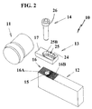
- Fig. 2 shows a tool 10 according to the present invention for form turning comprising a substantially rectangular holder 12, a cutting insert 13 having a cutting edge and a screw 14.
- the holder 12 may be made of steel, hard metal or speed steel.
- One free end of the holder 12 is intended to be secured to a lathe while the opposed other free end comprises a support surface 16 and a threaded hole 15.
- the threaded hole 15 has a conical entering bevel.
- the support surface 16 has a rectangular basic shape and comprises two grooved parts 16A, 16B. Each grooved part covers substantially half of the support surface 16 and comprises a number of from each other spaced, identical serrations or grooves.
- the grooves in the grooved parts have two main directions, which are perpendicular to each other.
- a second grooved part 16A is bordered by a first grooved part 16B.
- each groove in the first grooved part 16B intersects the jacket surface of the holder at two places while substantially each groove in the second grooved part 16A intersects the jacket surface of the holder at one place.
- Each groove is elongated and is substantially V-shaped in cross-section.
- Each groove has a biggest width W. The width is in the magnitude of 0,2 to 2 mm, preferably about 1,5 mm.
- Each groove has two flanks which, via a sharp or rounded transition, connect to a bottom. The flanks form an acute angle with each other. The angle lies within the interval of 40° to 80°, preferably 55° to 60°.
- Each surface is preferably planarly shaped and connects to an associated flank via an obtuse inner, soft or sharp, transition.
- the number of grooves in each grooved part depends of how the support surface of the cutting insert is formed and the number is chosen in the interval 5 to 20 grooves.
- the bottom may alternatively be described by a radius of about 0,2 to 0,4 mm.
- the design of the grooved parts 16A, 16B gives a considerably bigger specific surface than if that should be planar.
- the grooved parts 16A, 16B covers at least 80%, preferably 90-100%, of amenable area on the support surface 16.
- the first grooved part 16B has been made, through hobbing or grinding. Subsequently the second grooved part 16A has been machined with the same tool in direction perpendicularly to the first mentioned machining. To obtain full depth in each groove in the second grooved part 16A it is appropriate that the tool is fed somewhat into in the first grooved part 16B. Then said tool will also machine material which is part of the first grooved part 16B. Full pyramids or partly pyramid shaped tips are formed at the end of the second grooved part 16A in the first grooved part 16B.
- Figs. 1A-1G an elongated cutting insert 13 according to the present invention is shown.
- the cutting insert may be performed in hard metal, cermet or speed steel and shall be used for turning of profiles in a work piece 11.
- the cutting insert has a rectangular basic shape and comprises at least one cutting edge 17, which is provided in the forward end of the cutting insert.
- the cutting edge 17 is shaped at an intersection between an upper side or chip surface 18 and a clearance surface 19.
- the cutting edge 17 lies essentially in the plane P of the upper side 18 and is non-linear; i.e. it is intended to shape a contour in the work piece.
- the clearance surface 19 connects to a lower side or support surface 22 of the cutting insert.
- the support surface 22 has a rectangular basic shape and comprises two grooved parts: a first grooved part 23A and a second grooved part 23B. Each grooved part substantially covers the entire support surface 22 and comprises a number of from each other spaced, identical serrations or grooves. Grooves in the grooved parts have two main directions, which are perpendicular to each other.
- each groove in the first grooved part 23A intersects the clearance surface 19 while substantially each groove in the second grooved part 23B intersects both side faces 20A, 20B of the cutting insert.
- Each groove is elongated and is substantially V-shaped in cross-section.
- Each groove has a biggest width W and a depth.
- Each groove has two flanks which, via a sharp or rounded transition, connect to a bottom. The flanks form an obtuse angle with each other. The angle lies within the interval of 40° to 80°, preferably 55° to 60°.
- Each surface is preferably planarly shaped and connects to an associated flank via an obtuse inner, soft or sharp, transition.
- the number of grooves in each grooved part depends on how the support surface of the holder is formed and the number is chosen in the interval of 5 to 20 grooves.
- the bottom may alternatively be described by a radius of about 0,2 to 0,4 mm.
- the design of the grooved parts 23A, 23B gives a considerable bigger specific surface than if that should be planar.
- the grooved parts 23A, 23B covers at least 80%, preferably 90-100%, of amenable area on the support surface 22.
- the grooved parts 23A, 23B are displaced a distance W/2 relative to both directions for the grooved parts 16A and 16B of the holder 12.
- the cutting insert has an un-threaded hole 25 for receiving a screw or other clamping means.
- the hole 25 is elongated and placed centrally about the longitudinal axis CL of the cutting insert 13.
- the longitudinal axis CL is parallel with the feed direction F of the tool.
- the rear rounded end 25A of the hole 25 is placed at a distance L1 from an end surface 21 of the cutting insert.
- the distance L is substantially similar to the width W.
- the forward rounded end 25B of the hole 25 is placed at a distance L2 from of the cutting insert edge 17, see Fig. 1D.
- the distance L2 is substantially bigger than the distance L1, preferably at least 5 times bigger to enable many regrindings of the clearance surface 19. Consequently, the cutting insert 13 has been provided with an area 18A between the hole 25 and the cutting edge 17 which is intended to be ground after wear of the previous cutting edge.
- the hole 25 has a circumferential collar or shoulder 24, which is countersunk relative to the upper side 18 and against which a head 26 of the screw 14 will abut at tightened connection.
- the shoulder 24 connects upwardly to a circumferential wall 25C.
- the cutting edge 17 is longer than the biggest width of any of said ends 25A, 25B.
- the milling tool 10 (see Figs. 2 and 3) is mounted by putting by hand the support surface 22 of the cutting insert 13 against the support surface 16 of the holder 12 in one of the four possible positions such that the cutting edge 17 projects outside of the holder 12 free end. Thereby the groove directions for the support surface 22 are aligned with the groove directions for the support surface 16.
- the screw 14 is brought through the insert hole 25 and towards the threaded hole 15. By rotation of the screw 14 by means of a key which is in engagement with the key grip the cutting insert will be drawn firmly against the support surface, i.e. the position according to Fig. 3 has been achieved.
- the head 26 of the screw then abuts against the shoulder 24.
- the cutting insert 13 is now secured to the holder 12 in a satisfactory manner.
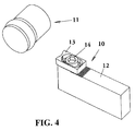
- Fig. 4 shows the position of the cutting insert 13 on the holder 12 after a number of regrindings of the clearance surface 19. In this position only the straight parts of the shoulder 24 are used. As the cutting insert becomes shorter the serrations of the second grooved part 16A are always used while fewer of serrations of the first grooved part 16B are used.
- each groove width W often corresponds to one or two regrindings, such that the grinding operator simply can adapt the regrinding with assistance from the cutting insert geometry.
- the clamping means contributes to the regrinding in such a manner that it guides the cutting insert in the feed direction F such that the cutting insert is not positioned incorrectly in the transversal direction.
- Fig. 5 are shown a number of different embodiments of forward ends of the profiling cutting insert, whereof all except one are asymmetrical about the longitudinal axis CL of the cutting insert.
- the gray portions below the forward ends signify the continuation of the cutting inserts comprising clamping means. All alternative embodiments comprise non-linear cutting edges for form turning.
- the clamping means may alternatively be developed with an internal pull rod, such as a stretching screw, where the hole 25 comprises an integral thread which cooperates with a threaded free end with the pull rod while the other end is secured at an axially movable nut.
- an internal pull rod such as a stretching screw
- the hole 25 comprises an integral thread which cooperates with a threaded free end with the pull rod while the other end is secured at an axially movable nut.
- the grooved parts have been made through direct pressing and sintring or through grinding.
- a cutting insert and a tool for form turning are provided where the cutting insert simply can be mounted on the holder, where the design of the cutting insert simplifies regrinding and where the tool comprises a minimum of parts.
- the cutting insert is rigidly held on the holder that is a big advantage when using asymmetrical, non-linear cutting edges for form turning.
Landscapes
- Engineering & Computer Science (AREA)
- Mechanical Engineering (AREA)
- Cutting Tools, Boring Holders, And Turrets (AREA)
- Milling Processes (AREA)
Applications Claiming Priority (2)
| Application Number | Priority Date | Filing Date | Title |
|---|---|---|---|
| SE0101752A SE523766C2 (sv) | 2001-05-18 | 2001-05-18 | Verktyg för profilsvarvning med frammatningsbart skär |
| SE0101752 | 2001-05-18 |
Publications (1)
| Publication Number | Publication Date |
|---|---|
| EP1260295A1 true EP1260295A1 (fr) | 2002-11-27 |
Family
ID=20284155
Family Applications (1)
| Application Number | Title | Priority Date | Filing Date |
|---|---|---|---|
| EP02445057A Withdrawn EP1260295A1 (fr) | 2001-05-18 | 2002-05-14 | Outil et plaquette de coupe |
Country Status (3)
| Country | Link |
|---|---|
| US (1) | US6872033B2 (fr) |
| EP (1) | EP1260295A1 (fr) |
| SE (1) | SE523766C2 (fr) |
Cited By (7)
| Publication number | Priority date | Publication date | Assignee | Title |
|---|---|---|---|---|
| WO2004002662A1 (fr) * | 2002-07-01 | 2004-01-08 | Seco Tools Ab | Dispositif d'accouplement pour machine a enlevement de copeaux, et outil, tete de coupe et mandrin associes |
| WO2004002661A1 (fr) * | 2002-07-01 | 2004-01-08 | Seco Tools Ab | Dispositif d'accouplement pour machine a enlevement de copeaux, et outil, tete de coupe et mandrin associe |
| GB2407786A (en) * | 2002-05-14 | 2005-05-11 | Vargus Ltd | Tool and method for the machine working of workpieces |
| WO2005080036A1 (fr) * | 2004-02-24 | 2005-09-01 | Sandvik Intellectual Property Ab | Outil de coupe et plaquette presentant des surfaces de contact dentelees entre le support et la plaquette |
| EP1661650A1 (fr) * | 2004-11-30 | 2006-05-31 | Applitec Moutier S.A. | Support d'outils |
| KR100994665B1 (ko) * | 2002-07-01 | 2010-11-16 | 쎄코 툴스 에이비 | 칩 제거 가공용 공구의 커플링, 공구, 커팅 헤드 및 홀더 |
| US10596633B1 (en) * | 2017-01-19 | 2020-03-24 | Consolidated Nuclear Security, LLC | Shaped cutting tool |
Families Citing this family (10)
| Publication number | Priority date | Publication date | Assignee | Title |
|---|---|---|---|---|
| SE527613C2 (sv) * | 2004-10-15 | 2006-04-25 | Seco Tools Ab | Verktyg för skärande bearbetning med en underläggsplatta med urtagningar |
| IL166007A (en) * | 2004-12-27 | 2009-02-11 | Iscar Ltd | Deburring tool and cutting insert therefor |
| SE528811C2 (sv) * | 2005-03-16 | 2007-02-20 | Sandvik Intellectual Property | Skär och verktyg för spånavskiljande bearbetning med vinklade ingreppsmedel, samt tillsats för dylika verktyg |
| US7472660B2 (en) * | 2005-10-13 | 2009-01-06 | Deere & Company | Seed tube for an agricultural seeding machine |
| USD550730S1 (en) | 2006-02-28 | 2007-09-11 | Manchester Tool Company | Cutting insert support/clamp |
| USD558802S1 (en) | 2006-02-28 | 2008-01-01 | Kennametal Inc. | Tool holder |
| CN101443146A (zh) | 2006-02-28 | 2009-05-27 | 钴碳化钨硬质合金公司 | 刀架组件 |
| US20070274794A1 (en) * | 2006-05-26 | 2007-11-29 | Cirino Thomas J | Oblique angle serration location and drive interface |
| SE530808C2 (sv) * | 2007-01-31 | 2008-09-16 | Sandvik Intellectual Property | Verktyg för spånavskiljande bearbetning, samt skär och grundkropp härför |
| US8764351B2 (en) | 2012-09-13 | 2014-07-01 | Iscar, Ltd. | Cutting insert with flexibility aperture and cutting tool therefor |
Citations (3)
| Publication number | Priority date | Publication date | Assignee | Title |
|---|---|---|---|---|
| GB595420A (en) * | 1944-08-28 | 1947-12-04 | Robert Alfred Dearden | Improvements in and relating to cutting tools for use on lathes and other machine tools |
| EP1038615A1 (fr) * | 1999-03-23 | 2000-09-27 | NGK Spark Plug Company Limited | Plaquette de coupe travaillant en plongée |
| US6146060A (en) * | 1997-06-30 | 2000-11-14 | Seco Tools Ab | Tool coupling and method for coupling two tool parts |
Family Cites Families (14)
| Publication number | Priority date | Publication date | Assignee | Title |
|---|---|---|---|---|
| US1354578A (en) * | 1917-08-24 | 1920-10-05 | United Shoe Machinery Corp | Inserted-tooth cutter |
| US1938717A (en) * | 1928-03-19 | 1933-12-12 | Nat Twist Drill & Tool Company | Cutting tool |
| US2453464A (en) * | 1945-05-31 | 1948-11-09 | Apex Tool & Cutter Company | Toolholder |
| US4437802A (en) * | 1981-09-14 | 1984-03-20 | Hall Jr John J | Boring tool having a detachable cutting blade |
| DE3333495A1 (de) * | 1983-09-16 | 1985-03-28 | J. Kühn GmbH & Co Präzisionswerkzeug KG, 4270 Dorsten | Drehbares zerspanungswerkzeug, insbesondere ausbohrkopf od. dgl. |
| US5725334A (en) * | 1993-03-29 | 1998-03-10 | Widia Gmbh | Cutting insert |
| US5924826A (en) * | 1994-04-27 | 1999-07-20 | Sandvik Ab | Cutting insert mounted on holder by rib-and-groove coupling |
| SE512053C2 (sv) * | 1998-12-22 | 2000-01-17 | Seco Tools Ab | Verktyg samt skärhuvud för skärande bearbetning |
| US6102630A (en) * | 1999-01-12 | 2000-08-15 | Tool Flo Manufacturing, Inc. | Ball nose end mill insert |
| US6220794B1 (en) * | 1999-03-05 | 2001-04-24 | Carboloy Inc. | Spherical seat cutting apparatus |
| JP2000280104A (ja) * | 1999-03-26 | 2000-10-10 | Ngk Spark Plug Co Ltd | プランジ切削用総形チップ |
| SE521183C2 (sv) * | 2001-03-15 | 2003-10-07 | Sandvik Ab | Skärhållare med organ för justering av skärlägeshållaren |
| US6761514B2 (en) * | 2001-10-19 | 2004-07-13 | Master Tool Corporation | Hollow mill tool |
| SE521579C2 (sv) * | 2002-03-21 | 2003-11-11 | Sandvik Ab | Verktyg samt skär för spånavskiljande bearbetning |
-
2001
- 2001-05-18 SE SE0101752A patent/SE523766C2/sv not_active IP Right Cessation
-
2002
- 2002-05-14 EP EP02445057A patent/EP1260295A1/fr not_active Withdrawn
- 2002-05-20 US US10/147,882 patent/US6872033B2/en not_active Expired - Fee Related
Patent Citations (3)
| Publication number | Priority date | Publication date | Assignee | Title |
|---|---|---|---|---|
| GB595420A (en) * | 1944-08-28 | 1947-12-04 | Robert Alfred Dearden | Improvements in and relating to cutting tools for use on lathes and other machine tools |
| US6146060A (en) * | 1997-06-30 | 2000-11-14 | Seco Tools Ab | Tool coupling and method for coupling two tool parts |
| EP1038615A1 (fr) * | 1999-03-23 | 2000-09-27 | NGK Spark Plug Company Limited | Plaquette de coupe travaillant en plongée |
Cited By (9)
| Publication number | Priority date | Publication date | Assignee | Title |
|---|---|---|---|---|
| GB2407786A (en) * | 2002-05-14 | 2005-05-11 | Vargus Ltd | Tool and method for the machine working of workpieces |
| WO2004002662A1 (fr) * | 2002-07-01 | 2004-01-08 | Seco Tools Ab | Dispositif d'accouplement pour machine a enlevement de copeaux, et outil, tete de coupe et mandrin associes |
| WO2004002661A1 (fr) * | 2002-07-01 | 2004-01-08 | Seco Tools Ab | Dispositif d'accouplement pour machine a enlevement de copeaux, et outil, tete de coupe et mandrin associe |
| KR100994665B1 (ko) * | 2002-07-01 | 2010-11-16 | 쎄코 툴스 에이비 | 칩 제거 가공용 공구의 커플링, 공구, 커팅 헤드 및 홀더 |
| WO2005080036A1 (fr) * | 2004-02-24 | 2005-09-01 | Sandvik Intellectual Property Ab | Outil de coupe et plaquette presentant des surfaces de contact dentelees entre le support et la plaquette |
| CN100515633C (zh) * | 2004-02-24 | 2009-07-22 | 山特维克知识产权股份有限公司 | 切削工具、切削工具的基体和切削工具的切削刀片 |
| US7585137B2 (en) | 2004-02-24 | 2009-09-08 | Sandvik Intellectual Property Ab | Cutting tool and insert with serrated contact surfaces between holder and insert |
| EP1661650A1 (fr) * | 2004-11-30 | 2006-05-31 | Applitec Moutier S.A. | Support d'outils |
| US10596633B1 (en) * | 2017-01-19 | 2020-03-24 | Consolidated Nuclear Security, LLC | Shaped cutting tool |
Also Published As
| Publication number | Publication date |
|---|---|
| US6872033B2 (en) | 2005-03-29 |
| SE0101752D0 (sv) | 2001-05-18 |
| SE0101752L (sv) | 2002-11-19 |
| US20020192042A1 (en) | 2002-12-19 |
| SE523766C2 (sv) | 2004-05-18 |
Similar Documents
| Publication | Publication Date | Title |
|---|---|---|
| EP1260295A1 (fr) | Outil et plaquette de coupe | |
| EP0642864B1 (fr) | Outil de coupe | |
| JP2546443Y2 (ja) | 金属切削インサート | |
| EP0416854A1 (fr) | Outil coupant | |
| JP2001506190A (ja) | 2つの工具部品を連結する工具継手と連結方法 | |
| WO1998007542A1 (fr) | Plaquette de coupe amovible | |
| IL93120A (en) | Cutting insert. | |
| CA1243194A (fr) | Outil de coupe | |
| TWI734825B (zh) | 具有以相對於一樞軸之力矩固定之可轉位切削嵌件的切削刀具 | |
| US5230590A (en) | Indexable insert for thread cutting and slotting | |
| US4118138A (en) | Cutting tool | |
| US5288180A (en) | Cutting tool | |
| US6126364A (en) | Reamer having spring-Biased insert clamps | |
| EP1283082A1 (fr) | Outil de coupe rotatif | |
| US5551676A (en) | Dual clamping vise | |
| US4137000A (en) | Cutting tool | |
| US20030039518A1 (en) | Cutting insert | |
| CA1074089A (fr) | Outil coupant | |
| US4230427A (en) | Bottom face mill | |
| US4327902A (en) | Coaxial workpiece arranger for rotary work holders of contour turning machines | |
| EP1210197B1 (fr) | Methode pour le serrage d'une plaquette de coupe, plaquette de coupe et outil de coupe | |
| JP2017177307A (ja) | 切削インサート及び切削工具 | |
| US5848562A (en) | Side operated clamp for resharpenable insert tool holder | |
| US4555202A (en) | Tool holder with tool | |
| US20010001275A1 (en) | Shaping lathe tool |
Legal Events
| Date | Code | Title | Description |
|---|---|---|---|
| PUAI | Public reference made under article 153(3) epc to a published international application that has entered the european phase |
Free format text: ORIGINAL CODE: 0009012 |
|
| AK | Designated contracting states |
Kind code of ref document: A1 Designated state(s): AT BE CH CY DE DK ES FI FR GB GR IE IT LI LU MC NL PT SE TR |
|
| AX | Request for extension of the european patent |
Free format text: AL;LT;LV;MK;RO;SI |
|
| 17P | Request for examination filed |
Effective date: 20030326 |
|
| AKX | Designation fees paid |
Designated state(s): DE FR GB IT SE |
|
| 17Q | First examination report despatched |
Effective date: 20041215 |
|
| STAA | Information on the status of an ep patent application or granted ep patent |
Free format text: STATUS: THE APPLICATION IS DEEMED TO BE WITHDRAWN |
|
| 18D | Application deemed to be withdrawn |
Effective date: 20050628 |