EP1260323A2 - Verfahren zum Steuern der Bewegung eines Roboters - Google Patents
Verfahren zum Steuern der Bewegung eines Roboters Download PDFInfo
- Publication number
- EP1260323A2 EP1260323A2 EP02011324A EP02011324A EP1260323A2 EP 1260323 A2 EP1260323 A2 EP 1260323A2 EP 02011324 A EP02011324 A EP 02011324A EP 02011324 A EP02011324 A EP 02011324A EP 1260323 A2 EP1260323 A2 EP 1260323A2
- Authority
- EP
- European Patent Office
- Prior art keywords
- robot
- axis
- energy
- absorbed
- mechanical
- Prior art date
- Legal status (The legal status is an assumption and is not a legal conclusion. Google has not performed a legal analysis and makes no representation as to the accuracy of the status listed.)
- Granted
Links
Images

Classifications
-
- B—PERFORMING OPERATIONS; TRANSPORTING
- B25—HAND TOOLS; PORTABLE POWER-DRIVEN TOOLS; MANIPULATORS
- B25J—MANIPULATORS; CHAMBERS PROVIDED WITH MANIPULATION DEVICES
- B25J9/00—Program-controlled manipulators
- B25J9/16—Program controls
- B25J9/1674—Program controls characterised by safety, monitoring, diagnostic
- B25J9/1676—Avoiding collision or forbidden zones
-
- B—PERFORMING OPERATIONS; TRANSPORTING
- B25—HAND TOOLS; PORTABLE POWER-DRIVEN TOOLS; MANIPULATORS
- B25J—MANIPULATORS; CHAMBERS PROVIDED WITH MANIPULATION DEVICES
- B25J9/00—Program-controlled manipulators
- B25J9/16—Program controls
- B25J9/1656—Program controls characterised by programming, planning systems for manipulators
- B25J9/1664—Program controls characterised by programming, planning systems for manipulators characterised by motion, path, trajectory planning
- B25J9/1666—Avoiding collision or forbidden zones
-
- G—PHYSICS
- G05—CONTROLLING; REGULATING
- G05B—CONTROL OR REGULATING SYSTEMS IN GENERAL; FUNCTIONAL ELEMENTS OF SUCH SYSTEMS; MONITORING OR TESTING ARRANGEMENTS FOR SUCH SYSTEMS OR ELEMENTS
- G05B2219/00—Program-control systems
- G05B2219/30—Nc systems
- G05B2219/39—Robotics, robotics to robotics hand
- G05B2219/39096—Self-collision, internal collison, collision between links of one robot
-
- G—PHYSICS
- G05—CONTROLLING; REGULATING
- G05B—CONTROL OR REGULATING SYSTEMS IN GENERAL; FUNCTIONAL ELEMENTS OF SUCH SYSTEMS; MONITORING OR TESTING ARRANGEMENTS FOR SUCH SYSTEMS OR ELEMENTS
- G05B2219/00—Program-control systems
- G05B2219/30—Nc systems
- G05B2219/40—Robotics, robotics mapping to robotics vision
- G05B2219/40215—Limit link kinetic energy to amount another element can dissipate upon impact
Definitions
- the invention relates to a method for controlling the movement of a robot.
- the robot drives a collision with the mentioned errors, also referred to as "crash", i.e. the colliding Link of the robot mechanics drives against him and his Mechanical buffer assigned to axis; the buffer will irreversibly deformed in a crash.
- the buffer is allowed with this Process must be destroyed and after the crash in everyone Case to be replaced. With this deformation kinetic energy of the robot in internal energy (heat) and deformation work of the buffer. Important is the protection of the robot itself.
- the control software then triggers a stop response. Overall, the Robots without damage even in this difficult exceptional situation its mechanics to stop.
- the mechanical However, buffer can be used without mechanical damage Robot elements only absorbed a limited amount of energy become.
- the object of the invention is therefore to avoid a control method of the aforementioned disadvantages to create a robot that under optimization the operating parameters of the robot, in particular lower Cycle times and the possibility of moving large payloads destruction of the robot is nevertheless reliably eliminated is.
- the stated object is achieved in a method of the type mentioned in the introduction in that kinetic energy from moving robot members (g 1 , ..., g i-1 , g i , g i + 1 , ..., g n ) an axis (A i ) is limited to the limit energy that can be absorbed without damage by a mechanical structure assigned to the corresponding axis (A i ).
- the invention thus includes the planning of a path movement while reducing the speed on the train, so that the physical kinetic energy that occurs in collision an axis against mechanical stops inside Energy is converted, not a given value exceeds.
- the axis speeds are limited on the condition that the energy limits, determined by the resilience of the mechanical structure, speed, Load and overhang. damage free limit energy that can be absorbed here the marginal energy that the manufacturer has, in particular through experiments, it was found that she had a Damage to any robot elements reliably excluded is.
- the kinetic energy of the robot members (g 1 , ..., g i-1 , g i , g i + 1 , to be absorbed by a mechanical structure assigned to a corresponding axis (A i ), ..., g n ) of each axis (A i ) is limited to the limit energy that can be absorbed by the mechanical structure without damage. Energy to be absorbed is the one that actually affects the structure.
- a preferred further development provides that the kinetic Energy depending on the moving masses and / or of the inertia tensor is limited.
- the affected structural unit therefore only has to have a part of the total kinetic energy in the overall system Robot is present: the energy of a robot link depends on the speeds of just the joints in the kinematic chain up to and including this link from. For this reason, the entire energy only has to be insofar be limited than that of the mechanical structure energy to be actually absorbed by this non-destructively can be absorbed, i.e. the energy absorption capacity does not exceed. On that of the mechanical So only a part of the structure-absorbable energy the total kinetic energy is limited; this can therefore be chosen larger than if you yourself on the Value that the structure absorbs non-destructively can. Hereby the dynamic limits of the robot be expanded.
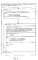
- the axis speed is reduced depending on the condition by before executing a movement command, taking into account the robot position and the payload the kinetic Energy depending on the programmed Axis speed is determined. If necessary, at The maximum speed is exceeded the affected axis reduced accordingly.
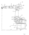
- Fig. 1 shows a robot R with a stationary base S, a first robot member 1 in located on this Form of a carousel, which around the vertical A1 axis of the robot R is rotatable, with one around the horizontal Axis A2 swiveling robot link 2, as well as a free one at the end of the rocker 2 further pivotable about the axis A3 Robot link 3, the robot arm. At its free end there is a robot hand 7 carrying a workpiece 6.
- With 8 is a motor for rotating the rocker 1 about the A1 axis designated.
- 9 denotes a motor for rotary motion the swing arm 2 around the A2 axis.
- 10 gives the engine for the Arm 3 and 11 are the motors for moving the hand 7 on.
- the robot is found with a relative small throat L1 between A1 axis and workpiece 6, the rocker is in a vertical position.
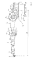
- Fig. 2 shows the same robot with maximum radius L2, which is achieved in that both rocker 2 and also robot arm 3 parallel in the same direction and horizontally are directed.
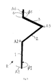
- FIG. 5 the limbs of a robot are shown schematically shown in a certain position, namely in a Position in which the axis A1 and the hand axis A6 open a straight line.
Landscapes
- Engineering & Computer Science (AREA)
- Robotics (AREA)
- Mechanical Engineering (AREA)
- Manipulator (AREA)
- Numerical Control (AREA)
Abstract
Description
- Fig. 1
- eine Seitenansicht eines Roboters mit vertikal gerichteter Schwinge und demgemäß geringer Ausladung;
- Fig. 2
- eine Seitenansicht eines Roboters mit maximaler Auslandung bei sowohl horizontal gerichteter Schwinge als auch horizontal gerichtetem Arm;
- Fig. 3
- eine schematische Darstellung der Situation bei einer Kollision bei der Bewegung des Karussell seines Roboters um die A1-Achse;
- Fig. 4
- eine schematische Darstellung zur KollisionsSituation bei der Kollision der Schwinger eines Roboters bei seiner Bewegung um die A2-Achse;
- Fig. 5
- eine spezielle Situation der Zuordnung an Achse A6 zur Achse A1 des Roboters bei der Kollision des Karussells bei seiner Bewegung um die A1-Achse, wobei sich die A6-Achse auf einer Geraden mit der A1Achse befindet; und
- Fig. 6
- ein Ablauf-Diagramm einer bevorzugten Ausgestaltung des erfindungsgemäßen Verfahrens.
Claims (3)
- Verfahren zum Steuern der Bewegung eines Roboters, dadurch gekennzeichnet, dass kinetische Energie von bewegten Robotergliedern (g1,..., gi-1, gi, gi+1,..., gn) um eine Achse (Ai) auf die durch eine der entsprechenden Achse (Ai) zugeordnete mechanische Struktur beschädigungsfrei aufnehmbare Grenzenergie beschränkt wird.
- Verfahren nach Anspruch 1, dadurch gekennzeichnet, dass die von einem einer entsprechenden Achse (Ai) zugeordnete mechanische Struktur aufzunehmende kinetische Energie der Roboterglieder (g1,..., gi-1, gi, gi+1,..., gn) jeder Achse (Ai) auf die durch den mechanischen Puffer beschädigungsfrei aufnehmbare Grenzenergie beschränkt wird.
- Verfahren nach Anspruch 1 oder 2, dadurch gekennzeichnet, dass die kinetische Energie in Abhängigkeit der bewegten Massen und/oder des Trägheitstensors begrenzt wird.
Applications Claiming Priority (2)
| Application Number | Priority Date | Filing Date | Title |
|---|---|---|---|
| DE10125445 | 2001-05-25 | ||
| DE10125445A DE10125445A1 (de) | 2001-05-25 | 2001-05-25 | Verfahren zum Steuern der Bewegung eines Roboters |
Publications (3)
| Publication Number | Publication Date |
|---|---|
| EP1260323A2 true EP1260323A2 (de) | 2002-11-27 |
| EP1260323A3 EP1260323A3 (de) | 2006-04-05 |
| EP1260323B1 EP1260323B1 (de) | 2008-12-10 |
Family
ID=7686062
Family Applications (1)
| Application Number | Title | Priority Date | Filing Date |
|---|---|---|---|
| EP02011324A Expired - Lifetime EP1260323B1 (de) | 2001-05-25 | 2002-05-23 | Verfahren zum Steuern der Bewegung eines Roboters |
Country Status (4)
| Country | Link |
|---|---|
| US (1) | US6791292B2 (de) |
| EP (1) | EP1260323B1 (de) |
| AT (1) | ATE416893T1 (de) |
| DE (2) | DE10125445A1 (de) |
Cited By (1)
| Publication number | Priority date | Publication date | Assignee | Title |
|---|---|---|---|---|
| EP2072195A1 (de) * | 2007-12-19 | 2009-06-24 | KUKA Roboter GmbH | Verfahren zum Steuern der Bewegung eines Roboters innerhalb eines Arbeitsraums |
Families Citing this family (5)
| Publication number | Priority date | Publication date | Assignee | Title |
|---|---|---|---|---|
| DE10361132B4 (de) * | 2003-06-18 | 2013-02-28 | Elan Schaltelemente Gmbh & Co. Kg | Verfahren zur Überwachung der Bewegung eines sich in mehreren Freiheitsgraden bewegenden Gefahr bringenden Objektes eines Handhabungsgerätes, wie Handhabungsmasse und/oder bewegliche Masse |
| DE102004057814B4 (de) * | 2004-11-30 | 2014-02-06 | Daimler Ag | Verfahren zum Steuern der Stellung von Werkstück und Werkzeug mit einem Roboter in einer Bearbeitungsmaschine |
| JP5650696B2 (ja) | 2012-09-04 | 2015-01-07 | ファナック株式会社 | スリットが形成された弾性変形体を有する機械式ストッパ装置、及び該機械式ストッパ装置を備えた多関節ロボット |
| WO2016037658A1 (en) * | 2014-09-12 | 2016-03-17 | Abb Technology Ltd | A robot controller, a robot unit and a method for controlling the operation of a robot unit |
| JP7558984B2 (ja) * | 2019-06-12 | 2024-10-01 | ウォルツマン,ダニエル,エズラ | 血管内器具 |
Family Cites Families (13)
| Publication number | Priority date | Publication date | Assignee | Title |
|---|---|---|---|---|
| US3935950A (en) * | 1973-09-04 | 1976-02-03 | Quality Steel Fabricators, Inc. | Industrial robot |
| US4603284A (en) * | 1984-06-05 | 1986-07-29 | Unimation, Inc. | Control system for manipulator apparatus with resolved compliant motion control |
| WO1990004500A1 (en) * | 1988-10-26 | 1990-05-03 | S Synnelius Engineering Ab | Method and apparatus for increasing the efficiency when displacing a detail by means of a robot |
| US5159249A (en) * | 1989-05-16 | 1992-10-27 | Dalila Megherbi | Method and apparatus for controlling robot motion at and near singularities and for robot mechanical design |
| JP3038972B2 (ja) * | 1991-04-03 | 2000-05-08 | ソニー株式会社 | 加減速パターン生成装置及びパターン生成方法 |
| AT401746B (de) * | 1995-04-13 | 1996-11-25 | Thomas Kastenmeier | Steuerungsverfahren für roboter, unter verwendung von geometrischen zwangsbedingungen und zufalls-suchverfahren |
| DE19517771A1 (de) * | 1995-05-15 | 1996-11-21 | Siemens Ag | Verfahren zum Betrieb einer numerisch gesteuerten Werkzeugmaschine oder eines Roboters |
| SE505981C2 (sv) * | 1996-02-14 | 1997-10-27 | Asea Brown Boveri | Förfarande för styrning av en industrirobot med hänsyn till moment och belastning |
| US5908122A (en) * | 1996-02-29 | 1999-06-01 | Sandia Corporation | Sway control method and system for rotary cranes |
| SE509443C2 (sv) * | 1997-05-15 | 1999-01-25 | Asea Brown Boveri | Förfarande för övervakning av en manipulators rörelsestyrning |
| DE19800552C2 (de) * | 1997-06-20 | 1999-04-22 | Deutsch Zentr Luft & Raumfahrt | Verfahren zur Kommandosteuerung eines Manipulators |
| DE19907989B4 (de) * | 1998-02-25 | 2009-03-19 | Liebherr-Werk Nenzing Gmbh | Verfahren zur Bahnregelung von Kranen und Vorrichtung zum bahngenauen Verfahren einer Last |
| DE20009039U1 (de) * | 2000-05-19 | 2001-07-05 | Kuka Roboter GmbH, 86165 Augsburg | Vorrichtung zur Bereichsüberwachung eines Roboters |
-
2001
- 2001-05-25 DE DE10125445A patent/DE10125445A1/de not_active Withdrawn
-
2002
- 2002-05-23 AT AT02011324T patent/ATE416893T1/de not_active IP Right Cessation
- 2002-05-23 DE DE50213091T patent/DE50213091D1/de not_active Expired - Lifetime
- 2002-05-23 US US10/154,519 patent/US6791292B2/en not_active Expired - Lifetime
- 2002-05-23 EP EP02011324A patent/EP1260323B1/de not_active Expired - Lifetime
Cited By (1)
| Publication number | Priority date | Publication date | Assignee | Title |
|---|---|---|---|---|
| EP2072195A1 (de) * | 2007-12-19 | 2009-06-24 | KUKA Roboter GmbH | Verfahren zum Steuern der Bewegung eines Roboters innerhalb eines Arbeitsraums |
Also Published As
| Publication number | Publication date |
|---|---|
| DE10125445A1 (de) | 2002-12-05 |
| EP1260323B1 (de) | 2008-12-10 |
| US20030020424A1 (en) | 2003-01-30 |
| US6791292B2 (en) | 2004-09-14 |
| DE50213091D1 (de) | 2009-01-22 |
| EP1260323A3 (de) | 2006-04-05 |
| ATE416893T1 (de) | 2008-12-15 |
Similar Documents
| Publication | Publication Date | Title |
|---|---|---|
| DE10226853B3 (de) | Verfahren zum Begrenzen der Krafteinwirkung eines Roboterteils | |
| EP3341164B1 (de) | Robotergreifer | |
| EP3017918B1 (de) | Flexibles taktzeitoptimiertes teilen eines arbeitsraums für roboter | |
| EP3365139B1 (de) | Parallelkinematik-roboter und verfahren zu dessen handhabung | |
| DE3784980T2 (de) | Kurzhubtransferpresse mit automatischer vorschubeinrichtung. | |
| EP2492062B1 (de) | Industrieroboter | |
| DE69317574T2 (de) | Gelenkroboter | |
| DE102009019633B4 (de) | Bewegung eines Menschen durch einen Manipulator | |
| WO2014170237A1 (de) | Industrieroboter mit einer an einem armausleger angeordneten antriebsanordnung | |
| EP2851162A2 (de) | Verfahren zum manuell geführten Verstellen der Pose eines Manipulatorarms eines Industrieroboters und zugehöriger Industrieroboter | |
| DE102018215960B4 (de) | Robotersystem | |
| EP1366868A1 (de) | Verfahren und Vorrichtung zur Kompensation der Trägheitskräfte eines Handhabungssystems | |
| EP2666727B1 (de) | Hubeinrichtung für eine Verpackungsmaschine | |
| DE60115645T9 (de) | Einrichtung einer werkzeugmaschine und verfahren zum ersetzen einer palette dieser einrichtung | |
| DE9306508U1 (de) | Vorrichtung zum Transport von Produkten | |
| EP2681016B1 (de) | Parallelroboter und steuerungsverfahren | |
| EP1260323A2 (de) | Verfahren zum Steuern der Bewegung eines Roboters | |
| EP0975254A2 (de) | Steuerung eines reinigungsautomaten | |
| WO2016005379A1 (de) | Maschine und verfahren zum betreiben einer maschine | |
| EP1010619B1 (de) | Füllmaschine zum Füllen von Ventilsäcken | |
| EP0743579B1 (de) | Verfahren zum Betrieb einer numerisch gesteuerten Werkzeugmaschine oder eines Roboters | |
| EP2444208B1 (de) | Handhabungsvorrichtung | |
| WO2011064120A1 (de) | Verfahren zum erstellen eines robotermodells und industrieroboter | |
| EP3946831B1 (de) | Vorgeben von sicheren geschwindigkeiten für einen robotermanipulator | |
| DE29616401U1 (de) | Mehrachsiger Industrieroboter |
Legal Events
| Date | Code | Title | Description |
|---|---|---|---|
| PUAI | Public reference made under article 153(3) epc to a published international application that has entered the european phase |
Free format text: ORIGINAL CODE: 0009012 |
|
| AK | Designated contracting states |
Kind code of ref document: A2 Designated state(s): AT BE CH CY DE DK ES FI FR GB GR IE IT LI LU MC NL PT SE TR |
|
| AX | Request for extension of the european patent |
Free format text: AL;LT;LV;MK;RO;SI |
|
| PUAL | Search report despatched |
Free format text: ORIGINAL CODE: 0009013 |
|
| AK | Designated contracting states |
Kind code of ref document: A3 Designated state(s): AT BE CH CY DE DK ES FI FR GB GR IE IT LI LU MC NL PT SE TR |
|
| AX | Request for extension of the european patent |
Extension state: AL LT LV MK RO SI |
|
| 17P | Request for examination filed |
Effective date: 20060914 |
|
| 17Q | First examination report despatched |
Effective date: 20061027 |
|
| AKX | Designation fees paid |
Designated state(s): AT BE CH CY DE DK ES FI FR GB GR IE IT LI LU MC NL PT SE TR |
|
| GRAP | Despatch of communication of intention to grant a patent |
Free format text: ORIGINAL CODE: EPIDOSNIGR1 |
|
| GRAS | Grant fee paid |
Free format text: ORIGINAL CODE: EPIDOSNIGR3 |
|
| GRAS | Grant fee paid |
Free format text: ORIGINAL CODE: EPIDOSNIGR3 |
|
| GRAA | (expected) grant |
Free format text: ORIGINAL CODE: 0009210 |
|
| AK | Designated contracting states |
Kind code of ref document: B1 Designated state(s): AT BE CH CY DE DK ES FI FR GB GR IE IT LI LU MC NL PT SE TR |
|
| REG | Reference to a national code |
Ref country code: GB Ref legal event code: FG4D Free format text: NOT ENGLISH |
|
| REG | Reference to a national code |
Ref country code: CH Ref legal event code: EP |
|
| RAP2 | Party data changed (patent owner data changed or rights of a patent transferred) |
Owner name: KUKA ROBOTER GMBH |
|
| REG | Reference to a national code |
Ref country code: IE Ref legal event code: FG4D Free format text: LANGUAGE OF EP DOCUMENT: GERMAN |
|
| REF | Corresponds to: |
Ref document number: 50213091 Country of ref document: DE Date of ref document: 20090122 Kind code of ref document: P |
|
| REG | Reference to a national code |
Ref country code: SE Ref legal event code: TRGR |
|
| NLT2 | Nl: modifications (of names), taken from the european patent patent bulletin |
Owner name: KUKA ROBOTER GMBH Effective date: 20081224 |
|
| PG25 | Lapsed in a contracting state [announced via postgrant information from national office to epo] |
Ref country code: FI Free format text: LAPSE BECAUSE OF FAILURE TO SUBMIT A TRANSLATION OF THE DESCRIPTION OR TO PAY THE FEE WITHIN THE PRESCRIBED TIME-LIMIT Effective date: 20081210 Ref country code: NL Free format text: LAPSE BECAUSE OF FAILURE TO SUBMIT A TRANSLATION OF THE DESCRIPTION OR TO PAY THE FEE WITHIN THE PRESCRIBED TIME-LIMIT Effective date: 20081210 |
|
| NLV1 | Nl: lapsed or annulled due to failure to fulfill the requirements of art. 29p and 29m of the patents act | ||
| REG | Reference to a national code |
Ref country code: IE Ref legal event code: FD4D |
|
| PG25 | Lapsed in a contracting state [announced via postgrant information from national office to epo] |
Ref country code: IE Free format text: LAPSE BECAUSE OF FAILURE TO SUBMIT A TRANSLATION OF THE DESCRIPTION OR TO PAY THE FEE WITHIN THE PRESCRIBED TIME-LIMIT Effective date: 20081210 Ref country code: ES Free format text: LAPSE BECAUSE OF FAILURE TO SUBMIT A TRANSLATION OF THE DESCRIPTION OR TO PAY THE FEE WITHIN THE PRESCRIBED TIME-LIMIT Effective date: 20090321 |
|
| PG25 | Lapsed in a contracting state [announced via postgrant information from national office to epo] |
Ref country code: PT Free format text: LAPSE BECAUSE OF FAILURE TO SUBMIT A TRANSLATION OF THE DESCRIPTION OR TO PAY THE FEE WITHIN THE PRESCRIBED TIME-LIMIT Effective date: 20090511 |
|
| PLBE | No opposition filed within time limit |
Free format text: ORIGINAL CODE: 0009261 |
|
| STAA | Information on the status of an ep patent application or granted ep patent |
Free format text: STATUS: NO OPPOSITION FILED WITHIN TIME LIMIT |
|
| PG25 | Lapsed in a contracting state [announced via postgrant information from national office to epo] |
Ref country code: DK Free format text: LAPSE BECAUSE OF FAILURE TO SUBMIT A TRANSLATION OF THE DESCRIPTION OR TO PAY THE FEE WITHIN THE PRESCRIBED TIME-LIMIT Effective date: 20081210 |
|
| 26N | No opposition filed |
Effective date: 20090911 |
|
| BERE | Be: lapsed |
Owner name: KUKA ROBOTER G.M.B.H. Effective date: 20090531 |
|
| PG25 | Lapsed in a contracting state [announced via postgrant information from national office to epo] |
Ref country code: MC Free format text: LAPSE BECAUSE OF NON-PAYMENT OF DUE FEES Effective date: 20090531 |
|
| REG | Reference to a national code |
Ref country code: CH Ref legal event code: PL |
|
| GBPC | Gb: european patent ceased through non-payment of renewal fee |
Effective date: 20090523 |
|
| PG25 | Lapsed in a contracting state [announced via postgrant information from national office to epo] |
Ref country code: LI Free format text: LAPSE BECAUSE OF NON-PAYMENT OF DUE FEES Effective date: 20090531 Ref country code: CH Free format text: LAPSE BECAUSE OF NON-PAYMENT OF DUE FEES Effective date: 20090531 |
|
| PG25 | Lapsed in a contracting state [announced via postgrant information from national office to epo] |
Ref country code: GB Free format text: LAPSE BECAUSE OF NON-PAYMENT OF DUE FEES Effective date: 20090523 |
|
| PG25 | Lapsed in a contracting state [announced via postgrant information from national office to epo] |
Ref country code: BE Free format text: LAPSE BECAUSE OF NON-PAYMENT OF DUE FEES Effective date: 20090531 |
|
| PG25 | Lapsed in a contracting state [announced via postgrant information from national office to epo] |
Ref country code: AT Free format text: LAPSE BECAUSE OF NON-PAYMENT OF DUE FEES Effective date: 20090523 |
|
| PG25 | Lapsed in a contracting state [announced via postgrant information from national office to epo] |
Ref country code: GR Free format text: LAPSE BECAUSE OF FAILURE TO SUBMIT A TRANSLATION OF THE DESCRIPTION OR TO PAY THE FEE WITHIN THE PRESCRIBED TIME-LIMIT Effective date: 20090311 |
|
| PG25 | Lapsed in a contracting state [announced via postgrant information from national office to epo] |
Ref country code: IT Free format text: LAPSE BECAUSE OF FAILURE TO SUBMIT A TRANSLATION OF THE DESCRIPTION OR TO PAY THE FEE WITHIN THE PRESCRIBED TIME-LIMIT Effective date: 20081210 |
|
| PG25 | Lapsed in a contracting state [announced via postgrant information from national office to epo] |
Ref country code: LU Free format text: LAPSE BECAUSE OF NON-PAYMENT OF DUE FEES Effective date: 20090523 |
|
| REG | Reference to a national code |
Ref country code: DE Ref legal event code: R081 Ref document number: 50213091 Country of ref document: DE Owner name: KUKA LABORATORIES GMBH, DE Free format text: FORMER OWNER: KUKA ROBOTER GMBH, 86165 AUGSBURG, DE Effective date: 20110418 Ref country code: DE Ref legal event code: R081 Ref document number: 50213091 Country of ref document: DE Owner name: KUKA ROBOTER GMBH, DE Free format text: FORMER OWNER: KUKA ROBOTER GMBH, 86165 AUGSBURG, DE Effective date: 20110418 |
|
| PG25 | Lapsed in a contracting state [announced via postgrant information from national office to epo] |
Ref country code: TR Free format text: LAPSE BECAUSE OF FAILURE TO SUBMIT A TRANSLATION OF THE DESCRIPTION OR TO PAY THE FEE WITHIN THE PRESCRIBED TIME-LIMIT Effective date: 20081210 |
|
| PG25 | Lapsed in a contracting state [announced via postgrant information from national office to epo] |
Ref country code: CY Free format text: LAPSE BECAUSE OF FAILURE TO SUBMIT A TRANSLATION OF THE DESCRIPTION OR TO PAY THE FEE WITHIN THE PRESCRIBED TIME-LIMIT Effective date: 20081210 |
|
| REG | Reference to a national code |
Ref country code: FR Ref legal event code: TP Owner name: KUKA LABORATORIES GMBH, DE Effective date: 20111114 |
|
| REG | Reference to a national code |
Ref country code: DE Ref legal event code: R081 Ref document number: 50213091 Country of ref document: DE Owner name: KUKA ROBOTER GMBH, DE Free format text: FORMER OWNER: KUKA LABORATORIES GMBH, 86165 AUGSBURG, DE |
|
| REG | Reference to a national code |
Ref country code: FR Ref legal event code: PLFP Year of fee payment: 15 |
|
| REG | Reference to a national code |
Ref country code: FR Ref legal event code: PLFP Year of fee payment: 16 |
|
| REG | Reference to a national code |
Ref country code: FR Ref legal event code: PLFP Year of fee payment: 17 |
|
| REG | Reference to a national code |
Ref country code: DE Ref legal event code: R081 Ref document number: 50213091 Country of ref document: DE Owner name: KUKA DEUTSCHLAND GMBH, DE Free format text: FORMER OWNER: KUKA ROBOTER GMBH, 86165 AUGSBURG, DE |
|
| PGFP | Annual fee paid to national office [announced via postgrant information from national office to epo] |
Ref country code: DE Payment date: 20200512 Year of fee payment: 19 Ref country code: FR Payment date: 20200414 Year of fee payment: 19 |
|
| PGFP | Annual fee paid to national office [announced via postgrant information from national office to epo] |
Ref country code: SE Payment date: 20200512 Year of fee payment: 19 |
|
| REG | Reference to a national code |
Ref country code: DE Ref legal event code: R119 Ref document number: 50213091 Country of ref document: DE |
|
| REG | Reference to a national code |
Ref country code: SE Ref legal event code: EUG |
|
| PG25 | Lapsed in a contracting state [announced via postgrant information from national office to epo] |
Ref country code: SE Free format text: LAPSE BECAUSE OF NON-PAYMENT OF DUE FEES Effective date: 20210524 |
|
| PG25 | Lapsed in a contracting state [announced via postgrant information from national office to epo] |
Ref country code: DE Free format text: LAPSE BECAUSE OF NON-PAYMENT OF DUE FEES Effective date: 20211201 |
|
| PG25 | Lapsed in a contracting state [announced via postgrant information from national office to epo] |
Ref country code: FR Free format text: LAPSE BECAUSE OF NON-PAYMENT OF DUE FEES Effective date: 20210531 |