EP1260328A2 - Trennmaschine - Google Patents
Trennmaschine Download PDFInfo
- Publication number
- EP1260328A2 EP1260328A2 EP02011453A EP02011453A EP1260328A2 EP 1260328 A2 EP1260328 A2 EP 1260328A2 EP 02011453 A EP02011453 A EP 02011453A EP 02011453 A EP02011453 A EP 02011453A EP 1260328 A2 EP1260328 A2 EP 1260328A2
- Authority
- EP
- European Patent Office
- Prior art keywords
- machine
- relative
- conveying
- cutting
- path
- Prior art date
- Legal status (The legal status is an assumption and is not a legal conclusion. Google has not performed a legal analysis and makes no representation as to the accuracy of the status listed.)
- Withdrawn
Links
Images


Classifications
-
- B—PERFORMING OPERATIONS; TRANSPORTING
- B27—WORKING OR PRESERVING WOOD OR SIMILAR MATERIAL; NAILING OR STAPLING MACHINES IN GENERAL
- B27B—SAWS FOR WOOD OR SIMILAR MATERIAL; COMPONENTS OR ACCESSORIES THEREFOR
- B27B31/00—Arrangements for conveying, loading, turning, adjusting, or discharging the log or timber, specially designed for saw mills or sawing machines
- B27B31/006—Arrangements for conveying, loading, turning, adjusting, or discharging the log or timber, specially designed for saw mills or sawing machines with chains or belts
-
- B—PERFORMING OPERATIONS; TRANSPORTING
- B23—MACHINE TOOLS; METAL-WORKING NOT OTHERWISE PROVIDED FOR
- B23D—PLANING; SLOTTING; SHEARING; BROACHING; SAWING; FILING; SCRAPING; LIKE OPERATIONS FOR WORKING METAL BY REMOVING MATERIAL, NOT OTHERWISE PROVIDED FOR
- B23D47/00—Sawing machines or sawing devices working with circular saw blades, characterised only by constructional features of particular parts
- B23D47/04—Sawing machines or sawing devices working with circular saw blades, characterised only by constructional features of particular parts of devices for feeding, positioning, clamping, or rotating work
- B23D47/042—Sawing machines or sawing devices working with circular saw blades, characterised only by constructional features of particular parts of devices for feeding, positioning, clamping, or rotating work for conveying work to, or discharging work from, the machine
-
- B—PERFORMING OPERATIONS; TRANSPORTING
- B27—WORKING OR PRESERVING WOOD OR SIMILAR MATERIAL; NAILING OR STAPLING MACHINES IN GENERAL
- B27B—SAWS FOR WOOD OR SIMILAR MATERIAL; COMPONENTS OR ACCESSORIES THEREFOR
- B27B5/00—Sawing machines working with circular or cylindrical saw blades; Components or equipment therefor
- B27B5/02—Sawing machines working with circular or cylindrical saw blades; Components or equipment therefor characterised by a special purpose only
- B27B5/06—Sawing machines working with circular or cylindrical saw blades; Components or equipment therefor characterised by a special purpose only for dividing plates in parts of determined size, e.g. panels
- B27B5/065—Sawing machines working with circular or cylindrical saw blades; Components or equipment therefor characterised by a special purpose only for dividing plates in parts of determined size, e.g. panels with feedable saw blades, e.g. arranged on a carriage
Definitions
- the present invention relates to a cutting machine for cutting bars of wood or similar into panels.
- the present invention may be used to advantage in the furniture industry, to which the following description refers purely by way of example.
- a cutting machine is used for cutting a number of parallel bars arranged side by side contacting one another.
- the cutting machine comprises a number of push members operated independently to feed respective bars in steps along respective substantially parallel paths and through a cutting station where, at each operating cycle of the machine, a cutting device cuts the bars along a cutting line substantially crosswise to the paths.
- a cutting machine for cutting bars of wood or similar into panels, the machine comprising a cutting station; conveying means for feeding at least two said bars along respective substantially parallel paths and through said cutting station; and cutting means located at the cutting station to cut said bars, in use, in a first direction substantially crosswise to said paths; and being characterized by also comprising guide means defining a feed channel for feeding each said bar along the respective said path.
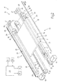
- Number 1 in Figure 1 indicates as a whole a cutting machine for cutting bars 2 of wood or similar into panels 3.
- Each bar 2 is substantially parallelepiped-shaped with a substantially rectangular section, and comprises two substantially parallel major lateral faces 2a; two substantially parallel minor lateral faces 2b perpendicular to faces 2a; and two substantially parallel minor lateral faces 2c perpendicular to faces 2a and 2b.
- Machine 1 comprises a number of (in the example shown, three) conveying units 4 extending in a horizontal direction 5 and along respective substantially parallel paths P; and a cutting device 6, which, at each operating cycle of machine 1 and at a cutting station 7 located along paths P, cuts bars 2 in a substantially horizontal direction 8 crosswise to direction 5.
- each unit 4 comprises two longitudinal members 9 extending parallel to direction 5, and each having a respective number of guide wheels 10, which are arranged successively in direction 5, are fitted to relative longitudinal member 9 to rotate about respective axes 11 parallel to one another and perpendicular to directions 5 and 8, and, together with wheels 10 of the other longitudinal member 9, define a feed channel 12.
- the two longitudinal members 9 are fitted in known manner to a number of fixed guides 13 parallel to one another and to direction 8, and can be moved linearly with respect to each other in direction 8 to selectively adjust the width, measured parallel to direction 8, of relative channel 12 as a function of the width, also measured parallel to direction 8, of relative bar 2.
- Unit 4 also comprises two conveying devices 14, 15 located upstream and downstream respectively from station 7 in direction 5 to define relative path P; device 14 provides for feeding relative bar 2 between an input station and station 7, and device 15 for feeding relative panel 3 between station 7 and an unloading station.
- Device 14 comprises two endless conveyors 16, each having a respective belt 17, which is movable in a vertical plane parallel to direction 5, and is looped about two pulleys 18 fitted in rotary manner to one of longitudinal members 9 and rotated in steps - with respect to longitudinal member 9 and by a motor 19 (in the example shown, an electric brushless motor) - about respective longitudinal axes 20 substantially parallel to each other and to direction 8.
- a motor 19 in the example shown, an electric brushless motor
- the two belts 17 have respective top conveying branches 21 coplanar with each other to define a conveying surface for relative bar 2, which is fed in direction 5 with faces 2b parallel to, and faces 2c perpendicular to, direction 5.
- device 14 also comprises a control unit 22, in turn comprising a number of control devices 23 equal in number to conveyors 16.
- Each device 23 comprises an endless conveyor 24 having a belt 25, which is movable in a vertical plane substantially parallel to direction 5, and is looped about two pulleys 26 - one of which is powered by a motor 27 (in the example shown, an electric brushless motor) - fitted in rotary manner to one of longitudinal members 9 and rotated, with respect to relative longitudinal member 9, about respective axes 28 substantially parallel to axes 20.
- a motor 27 in the example shown, an electric brushless motor
- Device 23 also comprises a control member 29, in turn comprising a touch-rod 30, which is fitted to belt 25, is designed to contact, in use, the rear face 2c in direction 5, and has a sensor 31 (in the example shown, an optical or magnetic sensor) whose position along relative path P is determined on a metric scale 32 fitted to relative longitudinal member 9 ( Figure 3) and parallel to direction 5.
- a control member 29 in turn comprising a touch-rod 30, which is fitted to belt 25, is designed to contact, in use, the rear face 2c in direction 5, and has a sensor 31 (in the example shown, an optical or magnetic sensor) whose position along relative path P is determined on a metric scale 32 fitted to relative longitudinal member 9 ( Figure 3) and parallel to direction 5.
- Unit 22 also comprises an electronic central control unit 33, which receives position signals from the two sensors 31, compares the signals, and selectively controls operation of the two motors 19 to keep the two sensors 31 aligned with each other in direction 8.
- the position of bar 2 with respect to direction 5 may vary due to different friction conditions between bar 2 and each of belts 17 and/or due to vibration of bar 2 caused by the flexible structure of conveyors 16. Since a constant contact pressure is maintained between both rods 30 and rear face 2c, the two sensors 31 are misaligned with respect to each other in direction 8 when faces 2c are positioned forming an angle of other than 90° with direction 5; in which case, electronic central control unit 33 receives two different position signals, one for each sensor 31, and commands at least one of motors 19 so that, by accelerating or decelerating relative conveyor 16, both sensors 31 are brought back into alignment in direction 8, i.e. faces 2b are again parallel to, and faces 2c perpendicular to, direction 5.
- device 15 comprises two endless conveyors 34, which are located in series with relative conveyors 16, and have respective belts 35 having respective conveying branches 36 substantially coplanar with branches 21.
- Each belt 35 is looped about two pulleys 37 fitted in rotary manner to one of longitudinal members 9 and rotated in steps - with respect to longitudinal member 9 and by a motor (in the example shown, an electric brushless motor not shown) - about respective longitudinal axes 39 substantially parallel to each other and to axes 20.
- device 6 comprises two uprights (not shown); a horizontal cross member 40 extending between the uprights (not shown) and parallel to direction 8; and a cutting member 41 fitted in known manner to cross member 40 to move linearly in direction 8 and in a vertical direction 42 perpendicular to directions 5 and 8, and which, at each operating cycle of machine 1, cuts all the bars 2 in station 7 along a cutting line A parallel to direction 8.
- device 6 also comprises a bottom supporting plate 43, which extends, parallel to direction 8, between conveyors 16 and 34, and is movable in direction 42 to and from a raised operating position, in which plate 43 is substantially coplanar with branches 21 and 36, so as to engage the bottom faces 2a of bars 2 at station 7 during the cutting operation.
- Device 6 also comprises a number of pressure wheels 44, which are located some upstream and some downstream from member 41 in direction 5, are mounted to rotate about respective axes 45 parallel to one another and to direction 8, and, when cutting bars 2, are positioned so as to engage top faces 2a of bars 2.
- each feed channel 12 houses a relative bar 2, which may differ from the bars 2 housed in the other channels 12 in terms of size, measured parallel to directions 5, 8 and/or 42, in terms of the color of surfaces 2a, 2b and/or 2c, and in terms of surface finish.
- Conveying units 4 are operated selectively and independently by an electronic central control unit 46 normally common to all of units 4, and which feeds each bar 2 in direction 5, so that, at cutting station 7, a respective portion of given length of each bar 2 is located downstream from cutting line A.
- conveyors 16 are deactivated; plate 43 is moved into the raised operating position; and cutting member 41, engaging a slit formed through plate 43, cuts bars 2 to obtain, from each bar 2, a panel 3 of a given length measured parallel to direction 5.
- plate 43 is moved into a lowered rest position; conveyors 34 are activated to feed panels 3 in direction 5 to said unloading station; and the above operating sequence is repeated at the next operating cycle of machine 1.
- Machine 1 has the following main advantages:
Landscapes
- Life Sciences & Earth Sciences (AREA)
- Engineering & Computer Science (AREA)
- Mechanical Engineering (AREA)
- Wood Science & Technology (AREA)
- Forests & Forestry (AREA)
- Milling, Drilling, And Turning Of Wood (AREA)
- Control And Other Processes For Unpacking Of Materials (AREA)
Applications Claiming Priority (2)
| Application Number | Priority Date | Filing Date | Title |
|---|---|---|---|
| IT2001TO000500A ITTO20010500A1 (it) | 2001-05-25 | 2001-05-25 | Macchina sezionatrice. |
| ITTO20010500 | 2001-05-25 |
Publications (2)
| Publication Number | Publication Date |
|---|---|
| EP1260328A2 true EP1260328A2 (de) | 2002-11-27 |
| EP1260328A3 EP1260328A3 (de) | 2003-05-28 |
Family
ID=11458897
Family Applications (1)
| Application Number | Title | Priority Date | Filing Date |
|---|---|---|---|
| EP02011453A Withdrawn EP1260328A3 (de) | 2001-05-25 | 2002-05-24 | Trennmaschine |
Country Status (2)
| Country | Link |
|---|---|
| EP (1) | EP1260328A3 (de) |
| IT (1) | ITTO20010500A1 (de) |
Cited By (6)
| Publication number | Priority date | Publication date | Assignee | Title |
|---|---|---|---|---|
| EP1767319A1 (de) * | 2005-09-27 | 2007-03-28 | Berry Finance Nv | Maschine zur Herstellung von Fugen in Platten und/oder zum Zuschneiden von Fliesen aus Platten sowie entsprechende Verfahren |
| WO2009107099A1 (en) * | 2008-02-29 | 2009-09-03 | Giben International S.P.A. | Panel saw machine |
| ITRM20090165A1 (it) * | 2009-04-10 | 2010-10-10 | Scm Group Spa | Macchina perfezionata per il taglio di pannelli. |
| CN102554344A (zh) * | 2012-03-16 | 2012-07-11 | 陈勇 | 连续裁切机 |
| US20220193802A1 (en) * | 2020-12-03 | 2022-06-23 | Ima Schelling Austria Gmbh | Panel cutting machine for cutting work pieces |
| AU2024278297B2 (en) * | 2023-06-20 | 2025-06-05 | Mitek Holdings, Inc. | Automated truss manufacturing and assembly system |
Family Cites Families (6)
| Publication number | Priority date | Publication date | Assignee | Title |
|---|---|---|---|---|
| DE1080287B (de) * | 1958-12-10 | 1960-04-21 | Meyer & Schwabedissen F | Aufteilformatsaege fuer Platten |
| DE1628923A1 (de) * | 1967-09-11 | 1973-10-18 | Elimar Wehner | Saegeeinrichtung |
| DE6606703U (de) * | 1968-05-16 | 1970-11-26 | Papenmeier Guenther | Auflagetisch mit aufteilformatsaege |
| CH493317A (de) * | 1968-11-21 | 1970-07-15 | Benuzzi Gino | Verfahren und Maschine zum Zerschneiden von grossen Holz-, Holzfaser-, Span- und Tischlerplatten oder dergleichen in kleinere Einzeltafeln |
| IT960565B (it) * | 1972-03-18 | 1973-11-30 | Giben Impianti Spa | Impianto perfezionato per attuare il rapido e preciso taglio a mi sure anche differenziate contempo raneamente in senso longitudinale e trasversale di pannelli di grandi dimensioni anche flessibili di legno od altro materiale disposti in pacchi di spessore adeguato |
| IT1056312B (it) * | 1975-12-23 | 1982-01-30 | Benuzzi G | Dispositivo per impostare automaticamente al taglio pacchidispositivo per impostare automaticamente al taglio pacchidi pannelli per derivare oannelli di ampiezza inferiure eda misure anche differenziate |
-
2001
- 2001-05-25 IT IT2001TO000500A patent/ITTO20010500A1/it unknown
-
2002
- 2002-05-24 EP EP02011453A patent/EP1260328A3/de not_active Withdrawn
Cited By (8)
| Publication number | Priority date | Publication date | Assignee | Title |
|---|---|---|---|---|
| EP1767319A1 (de) * | 2005-09-27 | 2007-03-28 | Berry Finance Nv | Maschine zur Herstellung von Fugen in Platten und/oder zum Zuschneiden von Fliesen aus Platten sowie entsprechende Verfahren |
| EP2239117B1 (de) * | 2005-09-27 | 2012-09-05 | Berry Finance Nv | Verfahren zur Herstellung von Fugen in Platten und zum Zuschneiden von Fliesen aus Platten |
| WO2009107099A1 (en) * | 2008-02-29 | 2009-09-03 | Giben International S.P.A. | Panel saw machine |
| ITRM20090165A1 (it) * | 2009-04-10 | 2010-10-10 | Scm Group Spa | Macchina perfezionata per il taglio di pannelli. |
| CN102554344A (zh) * | 2012-03-16 | 2012-07-11 | 陈勇 | 连续裁切机 |
| US20220193802A1 (en) * | 2020-12-03 | 2022-06-23 | Ima Schelling Austria Gmbh | Panel cutting machine for cutting work pieces |
| US12383969B2 (en) * | 2020-12-03 | 2025-08-12 | Ima Schelling Austria Gmbh | Panel cutting machine for cutting work pieces |
| AU2024278297B2 (en) * | 2023-06-20 | 2025-06-05 | Mitek Holdings, Inc. | Automated truss manufacturing and assembly system |
Also Published As
| Publication number | Publication date |
|---|---|
| ITTO20010500A1 (it) | 2002-11-25 |
| EP1260328A3 (de) | 2003-05-28 |
| ITTO20010500A0 (it) | 2001-05-25 |
Similar Documents
| Publication | Publication Date | Title |
|---|---|---|
| US6019213A (en) | Grouping and buffer apparatus | |
| KR960010226B1 (ko) | 평평한 작업편을 직각분류하도록 설계된 십자방형으로 이동하는 전동식 운반용 볼을 갖춘 작업대 | |
| US6247581B1 (en) | Adjustable length conveyor | |
| US5517748A (en) | Apparatus for conveying circuit boards through a component-mounting station | |
| US10357894B2 (en) | Rotary positioning fence | |
| EP0806383B1 (de) | Verfahren und Vorrichtung zum geordneten Abführen von ungeordnet zugeführten Produkten | |
| JP5802359B2 (ja) | 印刷物を自動的に切断するための切断装置 | |
| US5984301A (en) | Position adjustment conveyor | |
| EP1338381B1 (de) | Maschine zum Bearbeiten von Platten von Holz oder dergleichen | |
| CA1252286A (en) | Aligning device for boards | |
| US4750254A (en) | Continuously operating one-sided formatting and edge shaping machine | |
| EP2611719B1 (de) | Verfahren und system zur gruppierung von zu verpackenden produkten | |
| EP0972709B1 (de) | Verfahren und Vorrichtung zum Zuführen von Zuschnitten von Verpackungsmaterial in einer Verpackungsmaschine | |
| EP1231168A1 (de) | Förderlinie für Holzplatten oder dergleichen | |
| JPS6325918B2 (de) | ||
| CA1042316A (en) | Panel saw mechanism | |
| EP0719883B1 (de) | Vorrichtung zum Fördern, zu einer Endstation, von losen Textilgegenständen die selektiv durch mindestens zwei Zuführstationen zugeführt werden | |
| EP0972708A1 (de) | Vorrichtung zum Zuführen von Zuschnitten in einer Verpackungsmaschine | |
| EP1475204B1 (de) | Werkzeugmaschine zur Bearbeitung von Holzplatten oder dergleichen | |
| EP0424822B1 (de) | Plattensägemaschine | |
| ITTO20010500A1 (it) | Macchina sezionatrice. | |
| CN212385567U (zh) | 一种双向v-cut装置 | |
| US20100126629A1 (en) | Transport device for a finger jointing system | |
| JP7304491B2 (ja) | 積み重ね装置および積み重ね装置用の運搬ブロック | |
| ITMI20002034A1 (it) | Dispositivo di applicazione di copertine per macchina rilegatrice di libri. |
Legal Events
| Date | Code | Title | Description |
|---|---|---|---|
| PUAI | Public reference made under article 153(3) epc to a published international application that has entered the european phase |
Free format text: ORIGINAL CODE: 0009012 |
|
| AK | Designated contracting states |
Kind code of ref document: A2 Designated state(s): AT BE CH CY DE DK ES FI FR GB GR IE IT LI LU MC NL PT SE TR |
|
| AX | Request for extension of the european patent |
Free format text: AL;LT;LV;MK;RO;SI |
|
| PUAL | Search report despatched |
Free format text: ORIGINAL CODE: 0009013 |
|
| AK | Designated contracting states |
Designated state(s): AT BE CH CY DE DK ES FI FR GB GR IE IT LI LU MC NL PT SE TR |
|
| AX | Request for extension of the european patent |
Extension state: AL LT LV MK RO SI |
|
| RIC1 | Information provided on ipc code assigned before grant |
Ipc: 7B 27B 31/06 B Ipc: 7B 23D 47/04 B Ipc: 7B 27B 31/00 B Ipc: 7B 27B 5/065 A |
|
| 17P | Request for examination filed |
Effective date: 20031112 |
|
| AKX | Designation fees paid |
Designated state(s): AT BE CH CY DE DK ES FI FR GB GR IE IT LI LU MC NL PT SE TR |
|
| STAA | Information on the status of an ep patent application or granted ep patent |
Free format text: STATUS: THE APPLICATION IS DEEMED TO BE WITHDRAWN |
|
| 18D | Application deemed to be withdrawn |
Effective date: 20041201 |