EP1260343B1 - Dispositif de fabrication de seringues - Google Patents
Dispositif de fabrication de seringues Download PDFInfo
- Publication number
- EP1260343B1 EP1260343B1 EP02016173A EP02016173A EP1260343B1 EP 1260343 B1 EP1260343 B1 EP 1260343B1 EP 02016173 A EP02016173 A EP 02016173A EP 02016173 A EP02016173 A EP 02016173A EP 1260343 B1 EP1260343 B1 EP 1260343B1
- Authority
- EP
- European Patent Office
- Prior art keywords
- plunger
- insert
- barrel
- syringe
- locking means
- Prior art date
- Legal status (The legal status is an assumption and is not a legal conclusion. Google has not performed a legal analysis and makes no representation as to the accuracy of the status listed.)
- Expired - Lifetime
Links
- 238000000465 moulding Methods 0.000 claims description 15
- 238000012856 packing Methods 0.000 claims description 4
- 241000242541 Trematoda Species 0.000 description 11
- 238000013461 design Methods 0.000 description 10
- 238000004519 manufacturing process Methods 0.000 description 9
- 239000003814 drug Substances 0.000 description 8
- 229940079593 drug Drugs 0.000 description 8
- 238000000034 method Methods 0.000 description 8
- 238000002347 injection Methods 0.000 description 6
- 239000007924 injection Substances 0.000 description 6
- 230000004048 modification Effects 0.000 description 6
- 238000012986 modification Methods 0.000 description 6
- 239000007788 liquid Substances 0.000 description 5
- 230000008901 benefit Effects 0.000 description 4
- 239000008280 blood Substances 0.000 description 3
- 210000004369 blood Anatomy 0.000 description 3
- 229920003023 plastic Polymers 0.000 description 3
- 239000004033 plastic Substances 0.000 description 3
- 241000935974 Paralichthys dentatus Species 0.000 description 2
- 230000009471 action Effects 0.000 description 2
- 201000010099 disease Diseases 0.000 description 2
- 208000037265 diseases, disorders, signs and symptoms Diseases 0.000 description 2
- 238000003780 insertion Methods 0.000 description 2
- 230000037431 insertion Effects 0.000 description 2
- 230000008569 process Effects 0.000 description 2
- 208000030507 AIDS Diseases 0.000 description 1
- 238000007792 addition Methods 0.000 description 1
- 230000004888 barrier function Effects 0.000 description 1
- 210000004204 blood vessel Anatomy 0.000 description 1
- 210000001124 body fluid Anatomy 0.000 description 1
- 239000010839 body fluid Substances 0.000 description 1
- 230000008859 change Effects 0.000 description 1
- 238000006243 chemical reaction Methods 0.000 description 1
- 230000000295 complement effect Effects 0.000 description 1
- 238000010276 construction Methods 0.000 description 1
- 239000012530 fluid Substances 0.000 description 1
- 238000011010 flushing procedure Methods 0.000 description 1
- 239000003292 glue Substances 0.000 description 1
- 230000036541 health Effects 0.000 description 1
- 208000006454 hepatitis Diseases 0.000 description 1
- 231100000283 hepatitis Toxicity 0.000 description 1
- 230000001771 impaired effect Effects 0.000 description 1
- 238000001746 injection moulding Methods 0.000 description 1
- 230000003993 interaction Effects 0.000 description 1
- 239000000463 material Substances 0.000 description 1
- 238000002156 mixing Methods 0.000 description 1
- 230000002028 premature Effects 0.000 description 1
- 238000007789 sealing Methods 0.000 description 1
- 239000007787 solid Substances 0.000 description 1
- 210000003462 vein Anatomy 0.000 description 1
Images



Classifications
-
- A—HUMAN NECESSITIES
- A61—MEDICAL OR VETERINARY SCIENCE; HYGIENE
- A61M—DEVICES FOR INTRODUCING MEDIA INTO, OR ONTO, THE BODY; DEVICES FOR TRANSDUCING BODY MEDIA OR FOR TAKING MEDIA FROM THE BODY; DEVICES FOR PRODUCING OR ENDING SLEEP OR STUPOR
- A61M5/00—Devices for bringing media into the body in a subcutaneous, intra-vascular or intramuscular way; Accessories therefor, e.g. filling or cleaning devices, arm-rests
- A61M5/50—Devices for bringing media into the body in a subcutaneous, intra-vascular or intramuscular way; Accessories therefor, e.g. filling or cleaning devices, arm-rests having means for preventing re-use, or for indicating if defective, used, tampered with or unsterile
- A61M5/5066—Means for preventing re-use by disconnection of piston and piston-rod
-
- B—PERFORMING OPERATIONS; TRANSPORTING
- B29—WORKING OF PLASTICS; WORKING OF SUBSTANCES IN A PLASTIC STATE IN GENERAL
- B29C—SHAPING OR JOINING OF PLASTICS; SHAPING OF MATERIAL IN A PLASTIC STATE, NOT OTHERWISE PROVIDED FOR; AFTER-TREATMENT OF THE SHAPED PRODUCTS, e.g. REPAIRING
- B29C33/00—Moulds or cores; Details thereof or accessories therefor
- B29C33/30—Mounting, exchanging or centering
- B29C33/306—Exchangeable mould parts, e.g. cassette moulds, mould inserts
-
- B—PERFORMING OPERATIONS; TRANSPORTING
- B29—WORKING OF PLASTICS; WORKING OF SUBSTANCES IN A PLASTIC STATE IN GENERAL
- B29C—SHAPING OR JOINING OF PLASTICS; SHAPING OF MATERIAL IN A PLASTIC STATE, NOT OTHERWISE PROVIDED FOR; AFTER-TREATMENT OF THE SHAPED PRODUCTS, e.g. REPAIRING
- B29C33/00—Moulds or cores; Details thereof or accessories therefor
- B29C33/42—Moulds or cores; Details thereof or accessories therefor characterised by the shape of the moulding surface, e.g. ribs or grooves
-
- B—PERFORMING OPERATIONS; TRANSPORTING
- B29—WORKING OF PLASTICS; WORKING OF SUBSTANCES IN A PLASTIC STATE IN GENERAL
- B29C—SHAPING OR JOINING OF PLASTICS; SHAPING OF MATERIAL IN A PLASTIC STATE, NOT OTHERWISE PROVIDED FOR; AFTER-TREATMENT OF THE SHAPED PRODUCTS, e.g. REPAIRING
- B29C45/00—Injection moulding, i.e. forcing the required volume of moulding material through a nozzle into a closed mould; Apparatus therefor
- B29C45/17—Component parts, details or accessories; Auxiliary operations
- B29C45/26—Moulds
- B29C45/2673—Moulds with exchangeable mould parts, e.g. cassette moulds
-
- B—PERFORMING OPERATIONS; TRANSPORTING
- B29—WORKING OF PLASTICS; WORKING OF SUBSTANCES IN A PLASTIC STATE IN GENERAL
- B29C—SHAPING OR JOINING OF PLASTICS; SHAPING OF MATERIAL IN A PLASTIC STATE, NOT OTHERWISE PROVIDED FOR; AFTER-TREATMENT OF THE SHAPED PRODUCTS, e.g. REPAIRING
- B29C45/00—Injection moulding, i.e. forcing the required volume of moulding material through a nozzle into a closed mould; Apparatus therefor
- B29C45/17—Component parts, details or accessories; Auxiliary operations
- B29C45/26—Moulds
- B29C45/37—Mould cavity walls, i.e. the inner surface forming the mould cavity, e.g. linings
-
- B—PERFORMING OPERATIONS; TRANSPORTING
- B29—WORKING OF PLASTICS; WORKING OF SUBSTANCES IN A PLASTIC STATE IN GENERAL
- B29L—INDEXING SCHEME ASSOCIATED WITH SUBCLASS B29C, RELATING TO PARTICULAR ARTICLES
- B29L2031/00—Other particular articles
- B29L2031/753—Medical equipment; Accessories therefor
- B29L2031/7544—Injection needles, syringes
Definitions
- This invention relates to apparatus for making a syringe plunger, in particular for an autodestruct syringe, that is, one that can be used once only and is rendered disabled by the user during the process of normal use.
- Drug abusers have certain ritualistic techniques that must be fully accommodated if an autodestruct syringe design is to be successful and accepted in this vital market segment. Drug abusers can require to insert a needle many times before a suitable injection site is found, and make numerous small insertions and withdrawals during this process. After an injection a user may choose to flush out any drug left in the "dead space" of the syringe with their own blood several times.
- the primary area of concern with the spread of the previously mentioned diseases is that of the drug abuser, but all other areas can benefit from such a syringe, if it in no way hinders the user in the use of it.
- the ideal product is one which fits closely in with the current manufacturing techniques and assembly procedures, offers no resistance to the user, and is truly autodestruct so that it cannot be tampered with.
- EP-A-0 409 134 Such a design is shown in EP-A-0 409 134, which is intended to have the plunger and the barrel each moulded in one piece.
- a first aspect of the invention we provide apparatus for making a one-piece syringe plunger for sliding in a syringe barrel and having a locking means for engagement with an interruption means in the inner wall of the barrel, the apparatus comprising a two-part moulding tool, each part bearing an impression of a portion of the plunger such that the two parts co-operate to make the whole plunger, and characterised by each part having an insert bearing the impression for the locking means for the respective plunger portion, the insert being removably mounted in the part.
- the invention enables moulding tools for existing plungers to be modified to include the inserts with the locking means.
- the existing plungers can therefore be readily changed to include the locking means, but with low capital costs, as complete new tools are not required.
- Manufacture of the plunger is therefore the same as the existing plungers, and assembly of the plunger and the barrel is also similar. Because the plunger is a one-piece moulding no further assembly steps are required.
- inserts can themselves be readily changed.
- the moulding tool wears with use, but wear to the portion containing the locking means is critical, as it can render the locking means inoperable.
- the amount of acceptable wear for the locking means is much less than that for the rest of the plunger.
- the inserts with the locking means can therefore be changed often, to ensure accurate manufacture of the locking means.
- the inserts may be located at an existing split line in a tool part.
- Each insert may be attached to the tool part by pins inserted in aligned openings in the insert and tool part. Alternatively they may be secured by packing.
- the tool part may be provided with cavities for receiving the inserts.
- the cavities may be cut or machined in the tool part.
- Each insert may comprise one or more plates.
- an insert for use in apparatus for making a one-piece syringe plunger for sliding in a syringe barrel and having a locking means for engagement with an interruption means in the inner wall of the barrel, the apparatus comprising a two-part moulding tool, each part bearing an impression of a portion of the plunger such that the two parts co-operate to make the whole plunger, and characterised by the insert bearing the impression for the locking means of the respective plunger portion and being removably mounted in the corresponding tool part.
- the syringe comprises a barrel 1 and a plunger 7.
- the barrel has an inner cylindrical surface, an open proximal end 2 provided with a gripping flange 3 and a distal end 4 having an internal abutment shoulder 5 encircling a liquid outlet 6.
- the liquid outlet 6 can be arranged in a variety of ways as needed; the one shown is a luer slip design which holds a needle (not shown) with a friction fit; a luer lock onto which a needle screws; or can be arranged to accept a needle which is affixed permanently by glue, heat or some other means.
- the syringe plunger 7, shown inserted, comprises a rod 8 and finger plate 9, for gripping the plunger.
- an elastomeric sealing cap 15 adjacent to which are formed locking means 17 adapted to engage with means interrupting the cylindrical surface of the inner barrel wall, comprising grooves 10, 11, as explained in more detail below, in order to provide an autodestruct construction.
- the plunger 7 has the traditional rod 8 and finger plate 9 used for pushing in and pulling out the plunger.
- the plunger has a head 14 comprising a peg 13 over which is fixed an elastomeric cap 15 which forms a complete seal for liquids and gasses in the barrel 1.
- the peg 13 has a base 16 which supports the cap 15.
- On the opposite side of the base 16 is a tubular connection 18 to the plunger rod 8 which forms a strong yet slightly flexible join.
- the flukes are arranged so that their outer radial proximal edges 19 are in contact with the inner barrel wall when assembled.
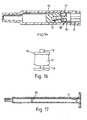
- the axial edge can be arranged with a straight edge as in Figure 4 or have an arcuate edge such as shown in Figure 16.
- the edge 19 may also have a variety of arrangements to best match the grooves in the barrel.
- the flukes 17 project outside the base 16 when viewed in Figure 5 which is a cross-sectional view as shown by the arrows V-V in Figure 4.
- the base does not touch the inner wall of the barrel but this drawing shows the arrangement of how the flukes will project and make contact with the barrel wall.
- connection 18 The position of the connection 18 is shown clearly in Figure 6.
- Figure 7 is a longitudinal section through the barrel showing the position and typical angle of location of the grooves 10, 11.
- the distal groove 10 is arranged in a suitable position for the use of the syringe.
- the groove 10 is in a position to allow for aspiration after the full injection stroke of the plunger. This is vital in some syringe use to allow the user to check the needle is still placed within a blood vessel, and/or to allow a drug abuser to flush the drug from the dead space 12 through drawing in and expelling blood.
- the proximal groove 11 is positioned to allow a complete rearward motion with the plunger, but does not allow the plunger to be removed.
- the groove 10 is shown in detail in Figure 8, and in section in Figure 9.
- the groove 10 extends round the whole of the circumference of the inner wall, and is of substantially triangular cross-section.
- the groove 10 has a first, distal edge 10' which is slightly inclined, by 20° to 30°, to the inner wall to allow forward movement of the plunger. It has a second, proximal edge 10" more sharply inclined, by about 60° to 70° to the inner wall, to engage the locking means 17 on withdrawal.
- the first and second edges are substantially perpendicular.
- the groove 10 is also arranged at an angle other than perpendicular to the longitudinal axis of the barrel 1.
- This angle which may be up to 30°, means that on advance of the elastomeric cap 15, the friction felt by the user is not the same as the friction experienced when advancing in and past a groove or projection arranged perpendicular to the barrel axis.
- the cap 15 meets the proximal edge of the groove 10 first.
- the elastomeric cap 15 has a leading edge which forms a tight seal with the inner wall of the barrel and exerts a slight outward pressure to achieve this seal. This pressure is only slightly affected when meeting the small area of groove 10 exposed. As the cap 15 moves forward it leaves the primary contact area and moves on and so is only in contact with a small area of change of resistance. This gives a smoother feel to the injection which is very much an advantage for the invention.
- the proximal groove 11 is similar to the distal groove 10.
- the grooves 10, 11 are very precise in cross-section and are very easy to manufacture in this arrangement. This is an advance from previous inventions, as theoretically it is very difficult to make such a groove in a barrel of one piece.
- a groove provides a much more solid form of a restrictive means compared to say a projection means.
- the advantage for moulding grooves 10, 11 is their angle to the longitudinal axis and the axis of withdrawal by the moulding core. This means the projection from the core which forms the groove is able to pass out of the moulded barrel without disturbing the soft inner wall of the barrel.
- the proximal groove 11 can be oriented 180° in axial rotation to the distal groove. This offers less resistance to the moulding core upon withdrawal as the distal projection upon it does not fully locate into the proximal groove 11.
- Figures 10 to 13 The operation of the syringe is shown in Figures 10 to 13.
- the syringe allows for "normal" use.
- Figure 10 shows the plunger in the position it is supplied in. If the plunger was inserted any further it would be rendered unusable due to the flukes 17 passing to the distal side of the groove 10.
- the user fills the syringe by pulling back the plunger as in Figure 11 and is at liberty to fill the syringe to the required level without restrictions. Sometimes a second fill is desired for instance when mixing two liquids in the barrel and this is unhindered.
- a drug abuser for example will after filling the syringe insert the needle under the skin in an effort to locate a vein suitable for injecting. This action requires retracting the plunger and drawing body fluid into the distal end of the syringe barrel. The colour and quantity of this fluid indicates to the user the suitability of the site. This technique and other are accommodated within the limits of the syringe.
- the plunger After the injection stroke the plunger will be in a position as shown in Figure 12. Then if it is required the plunger can be withdrawn a predetermined distance to accommodate aspiration of flushing as it is commonly known, but not further than the groove 10.
- Figure 13 shows the plunger in the position of maximum withdrawal. At this location the flukes will start to engage with the groove 11, which as described above prevents removal of the plunger and any subsequent tampering that could follow.
- Figure 15 shows a modification in which the interruption means comprises a projection 29 rather than a groove.
- the projection 29 is formed as an annulus which is angled to the axis of the barrel 1.
- the projection 29 is of triangular cross-section. It has a first proximal edge 29' inclined slightly to the inner wall, by between 20° and 30°, to allow forward movement of the plunger.
- the projection 29 also has a second, distal edge 29", sharply inclined to the inner wall, by about 60° to 70°, to engage the locking means on withdrawal.
- the projection 29 operates in a similar way to the grooves 10, 11.
- the flukes 17 pass over the projection 29 on forward movement of the plunger 7, but engage with it on withdrawal movement. The engagement twists the head of the plunger, so that it cannot withdraw further.
- the interruption means comprises a groove 10 followed immediately on its proximal side by a projection 29. This provides very satisfactory operation of the locking means 17.
- Figures 18 to 21 show a modified locking means.
- the locking means comprises a flexible cross-shaped disc 20.
- the disc 20 is connected to the base 16 by a short central connector 21, and the connection 18 is also shortened, and connects the disc 20 to the plunger rod 8.
- the disc 20 has a tapered periphery 22, which is smaller adjacent the base 16. This arrangement reduces the space taken up by the locking means.
- Figure 18 shows the plunger 7 at rest, while Figure 20 shows the plunger moving forwardly.
- the periphery of the disc 20 deflects away from the base 16, and the side remote from the base 16 engages the plunger rod 8.
- the disc 20 is therefore supported, and the tapered periphery 22 becomes substantially parallel to the barrel surface (not shown) so that the plunger 7 slides easily, and passes over the groove 10.
- the periphery of the disc 20 deflects the other way, and engages with the base 16. In this position it can still slide in the barrel 1, but on reaching a groove 10, 11 the outer edge of the tapered periphery 22 enters the groove and forms a shoulder preventing withdrawal movement out of the groove. As the disc 20 is supported on the base 16 the disc 20 cannot deflect further to slide past the groove 10.
- connection 18 breaks. It may also tend to break inadvertently if the plunger 7 is twisted in normal use. In a modification (not shown), the connection 18 is made larger and the connector 21 smaller in diameter. The connection 18 will then resist the tendency to break on twisting the plunger 7 in normal use.
- the deflected disc 20 acts as a lever on the base 16, so that the connector 21 breaks and the head of the plunger 7 "pops" off.
- the modified locking means are shown engaging with a groove 10 which is at right angles to the barrel axis. It would operate just as well with an angled groove, or with the angled projection 29 of Figure 15.
- the barrel 1 and plunger 7 are made of plastics material, by injection moulding. It will be appreciated that each is a single moulding, thus keeping down the cost of manufacture. In fact, the moulding tools for manufacture of existing plungers (those without the locking means) may be modified to include the locking means, in accordance with the invention
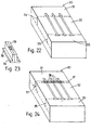
- Figure 22 shows one part 30 of a two-part moulding tool for a conventional plunger modified to include the locking means.
- the tool part 30 contains three impressions of half a plunger; a complementary tool part for containing the impressions of the other half of the plunger is not shown.
- the tool part is split into three portions 31, 32, 33 with the split lines 34, 35 adjacent the head and gripping flange respectively.
- inserts 36 containing the impression of half of the locking means are inserted into the part 30 at the split line 34.
- An insert 36 is shown in Figure 23; the three inserts 36 inserted into the tool part 30 are shown in Figure 24. The inserts are held in by packing 37.
- the inserts 36 are detachable so that they can easily be changed when they become worn. Wear to the insert containing the locking means is more critical than to the rest to the tool part, since it is essential to the invention that the locking means operates correctly. The inserts can therefore be changed, while the rest of the tool is still satisfactory, thus prolonging the life of the tool as a whole.
- the insert shown in Figure 23 has two plates 38, 39. In a modification (not shown) it could have one part, or more than two parts.
- each insert plate 36 may be mounted in the tool part 30 not by packing, but by pins inserted into openings in the tool part 30 and the plate 36.
- the part 30 may be split to accommodate the inserts 36, or have cavities machined in it to receive them.
Landscapes
- Engineering & Computer Science (AREA)
- Mechanical Engineering (AREA)
- Health & Medical Sciences (AREA)
- Manufacturing & Machinery (AREA)
- Biomedical Technology (AREA)
- Anesthesiology (AREA)
- Vascular Medicine (AREA)
- Heart & Thoracic Surgery (AREA)
- Hematology (AREA)
- Life Sciences & Earth Sciences (AREA)
- Animal Behavior & Ethology (AREA)
- General Health & Medical Sciences (AREA)
- Public Health (AREA)
- Veterinary Medicine (AREA)
- Infusion, Injection, And Reservoir Apparatuses (AREA)
Claims (8)
- Appareil permettant de constituer un piston de seringue (7) d'une seule pièce pour coulisser dans un cylindre de seringue (1) et ayant des moyens de verrouillage (17, 20) pour un engagement avec des moyens d'interruption (10, 11 ; 29) dans la paroi interne du cylindre, l'appareil comprenant un outil de moulage en deux parties, chaque partie (30) portant une empreinte d'une portion du piston (7) de telle façon que les deux parties coopèrent pour former le piston entier, caractérisé en ce que chaque partie (30) a un insert (36) portant l'empreinte pour les moyens de verrouillage (17, 20) pour la portion du piston correspondante, l'insert (36) étant monté de façon amovible sur la partie (30).
- Appareil selon la revendication 1, dans lequel l'insert (36) est situé sur une ligne de division existante (34) dans la partie outil.
- Appareil selon la revendication 1 ou 2, dans lequel chaque insert (36) est attaché à la partie outil (30) par des broches insérées dans les ouvertures alignées de l'insert (36) et de la partie outil (30).
- Appareil selon la revendication 1 ou 2, dans lequel chaque insert (36) est maintenu par un emballage (37).
- Appareil selon la revendication 1, dans lequel la partie outil (30) est pourvue de cavités destinées à recevoir les inserts (36).
- Appareil selon l'une quelconque des revendications 1 à 5, dans lequel chaque insert (36) comprend une ou plusieurs plaques (38, 39).
- Insert pour une utilisation pour la fabrication d'un piston de seringue d'une seule pièce (7) coulissant dans un cylindre de seringue (1) et ayant des moyens de verrouillage (17, 20) pour un engagement avec des moyens d'interruption (10, 11 ; 29) dans la partie interne du cylindre, l'appareil comprenant un outil de moulage en deux parties, chaque partie (30) portant une empreinte d'une portion du piston (7) de telle façon que les deux parties coopèrent pour former le piston entier, caractérisé en ce l'insert (36) porte l'empreinte pour les moyens de verrouillage (17, 20) sur la portion du piston correspondante et est monté de façon amovible sur la partie outil correspondante (30).
- Insert selon la revendication 7, dans lequel l'insert (36) comprend une ou plusieurs plaques (38, 39).
Applications Claiming Priority (5)
| Application Number | Priority Date | Filing Date | Title |
|---|---|---|---|
| GBGB9614807.7A GB9614807D0 (en) | 1996-07-15 | 1996-07-15 | Syringes |
| GB9614807 | 1996-07-15 | ||
| GB9709315A GB2315414B (en) | 1996-07-15 | 1997-05-09 | Syringes |
| GB9709315 | 1997-05-09 | ||
| EP97931912A EP0925083B1 (fr) | 1996-07-15 | 1997-07-11 | Seringue a usage unique |
Related Parent Applications (1)
| Application Number | Title | Priority Date | Filing Date |
|---|---|---|---|
| EP97931912A Division EP0925083B1 (fr) | 1996-07-15 | 1997-07-11 | Seringue a usage unique |
Publications (2)
| Publication Number | Publication Date |
|---|---|
| EP1260343A1 EP1260343A1 (fr) | 2002-11-27 |
| EP1260343B1 true EP1260343B1 (fr) | 2004-09-22 |
Family
ID=10796917
Family Applications (1)
| Application Number | Title | Priority Date | Filing Date |
|---|---|---|---|
| EP02016173A Expired - Lifetime EP1260343B1 (fr) | 1996-07-15 | 1997-07-11 | Dispositif de fabrication de seringues |
Country Status (10)
| Country | Link |
|---|---|
| EP (1) | EP1260343B1 (fr) |
| AR (1) | AR008777A1 (fr) |
| DK (1) | DK1260343T3 (fr) |
| EG (1) | EG20812A (fr) |
| GB (2) | GB9614807D0 (fr) |
| MY (1) | MY125689A (fr) |
| RU (1) | RU2196611C2 (fr) |
| SA (1) | SA97180267B1 (fr) |
| UY (1) | UY24623A1 (fr) |
| ZA (1) | ZA975906B (fr) |
Cited By (1)
| Publication number | Priority date | Publication date | Assignee | Title |
|---|---|---|---|---|
| US8287491B2 (en) | 2008-11-26 | 2012-10-16 | Becton, Dickinson And Company | Single-use auto-disable syringe |
Families Citing this family (6)
| Publication number | Priority date | Publication date | Assignee | Title |
|---|---|---|---|---|
| DE20312677U1 (de) | 2003-08-16 | 2004-12-23 | Schwarzbich, Jörg | Spritze mit einer Wiederverwendungssperre |
| WO2010127146A1 (fr) * | 2009-04-29 | 2010-11-04 | Abbott Biotechnology Ltd | Dispositif d'injection automatique |
| IT1398805B1 (it) * | 2009-06-11 | 2013-03-18 | Brev Angela Srl | Procedimento per la produzione di strumenti medicali |
| IT1394656B1 (it) * | 2009-07-03 | 2012-07-05 | Brev Angela Srl | Processo per la produzione e l'assemblaggio di una siringa per operazioni medicali |
| BR112017014941B1 (pt) * | 2015-01-16 | 2022-03-29 | Brevetti Angela S.R.L. | Processo para produção e montagem de um recipiente asséptico |
| CN107901297A (zh) * | 2017-10-25 | 2018-04-13 | 广东泰安模塑科技股份有限公司 | 一种更换镶件的结构 |
Family Cites Families (17)
| Publication number | Priority date | Publication date | Assignee | Title |
|---|---|---|---|---|
| US22977A (en) | 1859-02-15 | Improvement in harvesters | ||
| US3431601A (en) * | 1966-12-05 | 1969-03-11 | Willis L Lipscomb | Modular die |
| US3478937A (en) | 1968-01-22 | 1969-11-18 | Ida Solowey | Disposable single unit-dose syringe with locking plunger |
| US3951196A (en) | 1975-05-19 | 1976-04-20 | Consolidated Foods Corporation | Traverse rod assembly |
| FR2348708A1 (fr) | 1976-04-23 | 1977-11-18 | Becton Dickinson France | Ampoule-seringue et son procede d'utilisation |
| US4424817A (en) | 1981-07-01 | 1984-01-10 | Marquest Medical Products, Inc. | Syringe with means for automatically sealing a blood sample within the syringe |
| US4367738A (en) | 1981-10-28 | 1983-01-11 | Janssen Pharmaceutica Inc. | Pre-filled syringe for abusable drugs |
| GB2184657A (en) | 1985-12-19 | 1987-07-01 | Roger Hubert Morley | Hypodermic syringe |
| SU1512714A1 (ru) * | 1987-09-24 | 1989-10-07 | Chalyan Ruben T | Устройство дл зажима инструмента |
| JPH02502073A (ja) * | 1987-11-06 | 1990-07-12 | エルガス・ルイ・パウル | 再使用不能な注射器 |
| WO1989006146A1 (fr) * | 1987-12-30 | 1989-07-13 | Jacques Verlier | Seringue a usage unique |
| US5019045A (en) * | 1988-03-28 | 1991-05-28 | Lee Sang D | Hypodermic syringe with a locking needle assembly and syringe combination |
| AR240257A1 (es) * | 1989-03-22 | 1990-03-30 | Arcusin Carlos E | Jeringa autodescartable. |
| ES2014802A6 (es) * | 1989-07-17 | 1990-07-16 | Sempere Escudero Philippe | Jeringa de alta seguridad. |
| US5106372A (en) * | 1991-05-03 | 1992-04-21 | Sherwood Medical Company | Single use syringe |
| US5380295A (en) * | 1992-12-14 | 1995-01-10 | Mallinckrodt Medical, Inc. | Delivery apparatus with mechanism preventing rearward movement of a piston disposed therein |
| US5370620A (en) * | 1992-12-28 | 1994-12-06 | Shonfeld; David | Single use hypodermic syringe |
-
1996
- 1996-07-15 GB GBGB9614807.7A patent/GB9614807D0/en active Pending
-
1997
- 1997-05-09 GB GB9709315A patent/GB2315414B/en not_active Expired - Lifetime
- 1997-07-02 ZA ZA9705906A patent/ZA975906B/xx unknown
- 1997-07-11 EP EP02016173A patent/EP1260343B1/fr not_active Expired - Lifetime
- 1997-07-11 RU RU99102535/14A patent/RU2196611C2/ru not_active IP Right Cessation
- 1997-07-11 DK DK02016173T patent/DK1260343T3/da active
- 1997-07-14 MY MYPI97003181A patent/MY125689A/en unknown
- 1997-07-15 EG EG67097A patent/EG20812A/xx active
- 1997-07-15 AR ARP970103174A patent/AR008777A1/es active IP Right Grant
- 1997-07-15 UY UY24623A patent/UY24623A1/es not_active IP Right Cessation
- 1997-07-30 SA SA97180267A patent/SA97180267B1/ar unknown
Cited By (2)
| Publication number | Priority date | Publication date | Assignee | Title |
|---|---|---|---|---|
| US8287491B2 (en) | 2008-11-26 | 2012-10-16 | Becton, Dickinson And Company | Single-use auto-disable syringe |
| US9205205B2 (en) | 2008-11-26 | 2015-12-08 | Becton, Dickinson And Company | Single-use auto-disable syringe |
Also Published As
| Publication number | Publication date |
|---|---|
| DK1260343T3 (da) | 2004-11-08 |
| SA97180267B1 (ar) | 2005-12-12 |
| ZA975906B (en) | 1998-02-02 |
| GB2315414B (en) | 2000-11-01 |
| EG20812A (en) | 2000-03-29 |
| GB9614807D0 (en) | 1996-09-04 |
| UY24623A1 (es) | 1997-07-25 |
| RU2196611C2 (ru) | 2003-01-20 |
| GB2315414A (en) | 1998-02-04 |
| GB9709315D0 (en) | 1997-06-25 |
| HK1008938A1 (en) | 1999-05-21 |
| EP1260343A1 (fr) | 2002-11-27 |
| MY125689A (en) | 2006-08-30 |
| AR008777A1 (es) | 2000-02-23 |
Similar Documents
| Publication | Publication Date | Title |
|---|---|---|
| AP917A (en) | Syringes. | |
| CN112188906B (zh) | 药物自动输送装置 | |
| AU701878B2 (en) | Tamperproof retractable syringe | |
| US7351224B1 (en) | Retractable syringe assembly designed for one use | |
| JP3559557B2 (ja) | 密閉胴体を有する格納型注射器 | |
| US6183464B1 (en) | Safety syringe with retractable needle and universal luer coupling | |
| CA2727398C (fr) | Seringue avec mecanisme de mise hors de fonction | |
| CN101743029B (zh) | 具有减小无效空间的能拆卸针头注射器 | |
| US8920371B2 (en) | Syringe with disabling mechanism | |
| JP2001507963A (ja) | ノズル組立体用プランジャ | |
| CA2084305A1 (fr) | Seringue jetable | |
| EP1260343B1 (fr) | Dispositif de fabrication de seringues | |
| RU2534405C2 (ru) | Шприц с убирающейся иглой и режущей коронкой | |
| AU758110B2 (en) | Apparatus for making syringes | |
| EP2018198B1 (fr) | Seringue à usage unique | |
| KR20260037525A (ko) | 재사용 방지 구조를 갖는 시린지 | |
| KR20220142669A (ko) | 헤드 분리형 일회용 주사기 | |
| HK1069550B (en) | Tamperproof retractable syringe | |
| HK1122227A (en) | Syringe plunger assembly and barrel |
Legal Events
| Date | Code | Title | Description |
|---|---|---|---|
| PUAI | Public reference made under article 153(3) epc to a published international application that has entered the european phase |
Free format text: ORIGINAL CODE: 0009012 |
|
| 17P | Request for examination filed |
Effective date: 20020808 |
|
| AC | Divisional application: reference to earlier application |
Ref document number: 925083 Country of ref document: EP |
|
| AK | Designated contracting states |
Kind code of ref document: A1 Designated state(s): AT BE CH DE DK ES FR GR IE IT LI NL PT SE |
|
| AX | Request for extension of the european patent |
Free format text: RO PAYMENT 20020808 |
|
| 17Q | First examination report despatched |
Effective date: 20030224 |
|
| AKX | Designation fees paid |
Designated state(s): AT BE CH DE DK ES FR GR IE IT LI NL PT SE |
|
| AXX | Extension fees paid |
Extension state: RO Payment date: 20020808 |
|
| GRAP | Despatch of communication of intention to grant a patent |
Free format text: ORIGINAL CODE: EPIDOSNIGR1 |
|
| GRAS | Grant fee paid |
Free format text: ORIGINAL CODE: EPIDOSNIGR3 |
|
| GRAA | (expected) grant |
Free format text: ORIGINAL CODE: 0009210 |
|
| RAP1 | Party data changed (applicant data changed or rights of an application transferred) |
Owner name: STAR SYRINGE LIMITED |
|
| AC | Divisional application: reference to earlier application |
Ref document number: 0925083 Country of ref document: EP Kind code of ref document: P |
|
| AK | Designated contracting states |
Kind code of ref document: B1 Designated state(s): AT BE CH DE DK ES FR GR IE IT LI NL PT SE |
|
| AX | Request for extension of the european patent |
Extension state: RO |
|
| REG | Reference to a national code |
Ref country code: SE Ref legal event code: TRGR |
|
| REG | Reference to a national code |
Ref country code: CH Ref legal event code: EP |
|
| REG | Reference to a national code |
Ref country code: CH Ref legal event code: NV Representative=s name: E. BLUM & CO. PATENTANWAELTE |
|
| REG | Reference to a national code |
Ref country code: IE Ref legal event code: FG4D |
|
| REF | Corresponds to: |
Ref document number: 69730882 Country of ref document: DE Date of ref document: 20041028 Kind code of ref document: P |
|
| REG | Reference to a national code |
Ref country code: DK Ref legal event code: T3 |
|
| REG | Reference to a national code |
Ref country code: PT Ref legal event code: SC4A Free format text: AVAILABILITY OF NATIONAL TRANSLATION Effective date: 20040922 |
|
| REG | Reference to a national code |
Ref country code: GR Ref legal event code: EP Ref document number: 20040403875 Country of ref document: GR |
|
| REG | Reference to a national code |
Ref country code: ES Ref legal event code: FG2A Ref document number: 2229027 Country of ref document: ES Kind code of ref document: T3 |
|
| ET | Fr: translation filed | ||
| PLBE | No opposition filed within time limit |
Free format text: ORIGINAL CODE: 0009261 |
|
| STAA | Information on the status of an ep patent application or granted ep patent |
Free format text: STATUS: NO OPPOSITION FILED WITHIN TIME LIMIT |
|
| 26N | No opposition filed |
Effective date: 20050623 |
|
| REG | Reference to a national code |
Ref country code: CH Ref legal event code: PFA Owner name: STAR SYRINGE LIMITED Free format text: STAR SYRINGE LIMITED#GOSSARD HOUSE, 7-8 SAVILE ROW#LONDON W1X 1AF (GB) -TRANSFER TO- STAR SYRINGE LIMITED#GOSSARD HOUSE, 7-8 SAVILE ROW#LONDON W1X 1AF (GB) |
|
| REG | Reference to a national code |
Ref country code: FR Ref legal event code: PLFP Year of fee payment: 19 |
|
| PGFP | Annual fee paid to national office [announced via postgrant information from national office to epo] |
Ref country code: NL Payment date: 20150803 Year of fee payment: 19 |
|
| PGFP | Annual fee paid to national office [announced via postgrant information from national office to epo] |
Ref country code: DE Payment date: 20150727 Year of fee payment: 19 Ref country code: PT Payment date: 20150707 Year of fee payment: 19 Ref country code: IE Payment date: 20150724 Year of fee payment: 19 Ref country code: CH Payment date: 20150728 Year of fee payment: 19 Ref country code: DK Payment date: 20150731 Year of fee payment: 19 |
|
| PGFP | Annual fee paid to national office [announced via postgrant information from national office to epo] |
Ref country code: BE Payment date: 20150730 Year of fee payment: 19 Ref country code: GR Payment date: 20150728 Year of fee payment: 19 Ref country code: AT Payment date: 20150727 Year of fee payment: 19 Ref country code: SE Payment date: 20150731 Year of fee payment: 19 Ref country code: FR Payment date: 20150630 Year of fee payment: 19 |
|
| PGFP | Annual fee paid to national office [announced via postgrant information from national office to epo] |
Ref country code: IT Payment date: 20160630 Year of fee payment: 20 |
|
| PG25 | Lapsed in a contracting state [announced via postgrant information from national office to epo] |
Ref country code: BE Free format text: LAPSE BECAUSE OF NON-PAYMENT OF DUE FEES Effective date: 20160731 |
|
| PGFP | Annual fee paid to national office [announced via postgrant information from national office to epo] |
Ref country code: ES Payment date: 20160707 Year of fee payment: 20 |
|
| REG | Reference to a national code |
Ref country code: DE Ref legal event code: R119 Ref document number: 69730882 Country of ref document: DE |
|
| REG | Reference to a national code |
Ref country code: DK Ref legal event code: EBP Effective date: 20170131 |
|
| REG | Reference to a national code |
Ref country code: CH Ref legal event code: PL |
|
| REG | Reference to a national code |
Ref country code: NL Ref legal event code: MM Effective date: 20160801 |
|
| REG | Reference to a national code |
Ref country code: SE Ref legal event code: EUG |
|
| REG | Reference to a national code |
Ref country code: AT Ref legal event code: MM01 Ref document number: 276866 Country of ref document: AT Kind code of ref document: T Effective date: 20160711 |
|
| REG | Reference to a national code |
Ref country code: GR Ref legal event code: ML Ref document number: 20040403875 Country of ref document: GR Effective date: 20170207 |
|
| PG25 | Lapsed in a contracting state [announced via postgrant information from national office to epo] |
Ref country code: CH Free format text: LAPSE BECAUSE OF NON-PAYMENT OF DUE FEES Effective date: 20160731 Ref country code: GR Free format text: LAPSE BECAUSE OF NON-PAYMENT OF DUE FEES Effective date: 20170207 Ref country code: NL Free format text: LAPSE BECAUSE OF NON-PAYMENT OF DUE FEES Effective date: 20160801 Ref country code: DE Free format text: LAPSE BECAUSE OF NON-PAYMENT OF DUE FEES Effective date: 20170201 Ref country code: FR Free format text: LAPSE BECAUSE OF NON-PAYMENT OF DUE FEES Effective date: 20160801 Ref country code: LI Free format text: LAPSE BECAUSE OF NON-PAYMENT OF DUE FEES Effective date: 20160731 Ref country code: SE Free format text: LAPSE BECAUSE OF NON-PAYMENT OF DUE FEES Effective date: 20160712 |
|
| REG | Reference to a national code |
Ref country code: FR Ref legal event code: ST Effective date: 20170331 |
|
| REG | Reference to a national code |
Ref country code: IE Ref legal event code: MM4A |
|
| PG25 | Lapsed in a contracting state [announced via postgrant information from national office to epo] |
Ref country code: PT Free format text: LAPSE BECAUSE OF NON-PAYMENT OF DUE FEES Effective date: 20170111 Ref country code: AT Free format text: LAPSE BECAUSE OF NON-PAYMENT OF DUE FEES Effective date: 20160711 |
|
| PG25 | Lapsed in a contracting state [announced via postgrant information from national office to epo] |
Ref country code: IE Free format text: LAPSE BECAUSE OF NON-PAYMENT OF DUE FEES Effective date: 20160711 |
|
| PG25 | Lapsed in a contracting state [announced via postgrant information from national office to epo] |
Ref country code: PT Free format text: LAPSE BECAUSE OF EXPIRATION OF PROTECTION Effective date: 20170718 |
|
| PG25 | Lapsed in a contracting state [announced via postgrant information from national office to epo] |
Ref country code: DK Free format text: LAPSE BECAUSE OF NON-PAYMENT OF DUE FEES Effective date: 20160731 |
|
| REG | Reference to a national code |
Ref country code: ES Ref legal event code: FD2A Effective date: 20180508 |
|
| PG25 | Lapsed in a contracting state [announced via postgrant information from national office to epo] |
Ref country code: ES Free format text: LAPSE BECAUSE OF EXPIRATION OF PROTECTION Effective date: 20170712 Ref country code: PT Free format text: LAPSE BECAUSE OF EXPIRATION OF PROTECTION Effective date: 20150711 |