EP1260390A2 - Aufhängungssystem mit einer Feder - Google Patents
Aufhängungssystem mit einer Feder Download PDFInfo
- Publication number
- EP1260390A2 EP1260390A2 EP02005929A EP02005929A EP1260390A2 EP 1260390 A2 EP1260390 A2 EP 1260390A2 EP 02005929 A EP02005929 A EP 02005929A EP 02005929 A EP02005929 A EP 02005929A EP 1260390 A2 EP1260390 A2 EP 1260390A2
- Authority
- EP
- European Patent Office
- Prior art keywords
- spring
- helical compression
- compression spring
- center line
- shock absorber
- Prior art date
- Legal status (The legal status is an assumption and is not a legal conclusion. Google has not performed a legal analysis and makes no representation as to the accuracy of the status listed.)
- Granted
Links
Images


Classifications
-
- B—PERFORMING OPERATIONS; TRANSPORTING
- B60—VEHICLES IN GENERAL
- B60G—VEHICLE SUSPENSION ARRANGEMENTS
- B60G3/00—Resilient suspensions for a single wheel
- B60G3/02—Resilient suspensions for a single wheel with a single pivoted arm
- B60G3/04—Resilient suspensions for a single wheel with a single pivoted arm the arm being essentially transverse to the longitudinal axis of the vehicle
- B60G3/06—Resilient suspensions for a single wheel with a single pivoted arm the arm being essentially transverse to the longitudinal axis of the vehicle the arm being rigid
-
- B—PERFORMING OPERATIONS; TRANSPORTING
- B60—VEHICLES IN GENERAL
- B60G—VEHICLE SUSPENSION ARRANGEMENTS
- B60G11/00—Resilient suspensions characterised by arrangement, location or kind of springs
- B60G11/14—Resilient suspensions characterised by arrangement, location or kind of springs having helical, spiral or coil springs only
-
- B—PERFORMING OPERATIONS; TRANSPORTING
- B60—VEHICLES IN GENERAL
- B60G—VEHICLE SUSPENSION ARRANGEMENTS
- B60G15/00—Resilient suspensions characterised by arrangement, location or type of combined spring and vibration damper, e.g. telescopic type
- B60G15/02—Resilient suspensions characterised by arrangement, location or type of combined spring and vibration damper, e.g. telescopic type having mechanical spring
- B60G15/06—Resilient suspensions characterised by arrangement, location or type of combined spring and vibration damper, e.g. telescopic type having mechanical spring and fluid damper
- B60G15/062—Resilient suspensions characterised by arrangement, location or type of combined spring and vibration damper, e.g. telescopic type having mechanical spring and fluid damper the spring being arranged around the damper
- B60G15/063—Resilient suspensions characterised by arrangement, location or type of combined spring and vibration damper, e.g. telescopic type having mechanical spring and fluid damper the spring being arranged around the damper characterised by the mounting of the spring on the damper
-
- B—PERFORMING OPERATIONS; TRANSPORTING
- B60—VEHICLES IN GENERAL
- B60G—VEHICLE SUSPENSION ARRANGEMENTS
- B60G2200/00—Indexing codes relating to suspension types
- B60G2200/10—Independent suspensions
- B60G2200/14—Independent suspensions with lateral arms
- B60G2200/142—Independent suspensions with lateral arms with a single lateral arm, e.g. MacPherson type
-
- B—PERFORMING OPERATIONS; TRANSPORTING
- B60—VEHICLES IN GENERAL
- B60G—VEHICLE SUSPENSION ARRANGEMENTS
- B60G2202/00—Indexing codes relating to the type of spring, damper or actuator
- B60G2202/10—Type of spring
- B60G2202/12—Wound spring
-
- B—PERFORMING OPERATIONS; TRANSPORTING
- B60—VEHICLES IN GENERAL
- B60G—VEHICLE SUSPENSION ARRANGEMENTS
- B60G2206/00—Indexing codes related to the manufacturing of suspensions: constructional features, the materials used, procedures or tools
- B60G2206/01—Constructional features of suspension elements, e.g. arms, dampers, springs
- B60G2206/40—Constructional features of dampers and/or springs
- B60G2206/42—Springs
- B60G2206/426—Coil springs having a particular shape, e.g. curved axis, pig-tail end coils
Definitions
- Suspension spring Suspension spring
- the helical compression spring preferably is designed so that transverse forces at least partially by the helical compression spring be compensated for without the shear force compensating effect the helical compression spring on the shock absorber.
- the Helical compression spring initially arranged concentrically to the shock absorber axis his. The whole must then be at the upper support point, i.e. on the body transverse force occurring is absorbed by the piston rod of the shock absorber become. This has considerable frictional forces on the piston of the shock absorber and consequently jerky deflection and rebound Episode.
- the helical compression spring has been built into the strut for a long time a that the spring force line of action with the shock absorber axis forms an acute angle.
- the angle between the spring force line should be the helical compression spring and the shock absorber axis Correspond to the angle between the support action line and the shock absorber axis.
- the angle between the Spring force action line of the helical compression spring and the shock absorber axis only smaller than the angle between the support line of action and the shock absorber axis can be realized because the continuity of the shock absorber due to the helical compression spring and sufficient freedom of movement of the wheel still have to be guaranteed.
- German patent specification 37 43 450 is the problem mentioned above "Shear forces on the shock absorber or on the piston rod of the shock absorber” in described and shown individually, namely first in column 1, line 26, to column 2, line 13, and in column 2, line 37, to column 3, line 18. Described and is also shown in German Patent 37 43 450 Measure “helical compression spring, the spring center line of which is unloaded has an approximately C-shaped course ", namely in column 2, lines 14 to 19, and in column 3, lines 19 to 35, with reference to FIG. 5. In the German patent 37 43 450 is particularly the measure "Helical compression spring, the spring center line of which is unloaded about S-shaped course "has been described and illustrated, namely in Column 3, lines 42 to 64, and in Column 4, lines 1 to 29, with reference on Fig.
- the invention relates to a wheel suspension
- the u. a. belongs to a helical compression spring and being the helical compression spring is preferably designed so that transverse forces by the helical compression spring are at least partially compensated for without the shear force compensating Effect of the helical compression spring on the shock absorber.
- the helical compression spring is designed so that by the helical compression spring Lateral forces are at least partially compensated, notably.... "are above all - but by no means exclusively - those previously described in detail Measures "helical compression spring, the spring center line of which is unloaded State has an approximately C-shaped course "and" helical compression spring, whose spring center line is approximately S-shaped in the unloaded state History meant ".
- a first method for determining the spring center lines of helical compression springs is characterized in that the envelope of the Helical compression spring is constructed and that then from the constructed Envelope jacket the envelope jacket centerline is determined using the spring centerline is equated. This procedure is only applicable to a limited extent; it fails particularly where spring turns with changing Winding diameter are present.
- Another method of determination the spring center line of helical compression springs is characterized by that from the arithmetic mean of the winding points in each case Centers of the spring turn are determined and that the connection of the the spring center line thus represents certain centers of the spring turns.
- the spring centerline of helical compression springs can also be determined by the projections of the individual spring turns be considered in a plane that as the center of each spring turn the center of a circle is assumed to be attached to the spring coil is approximated, and that the centers of the spring coils thus obtained be connected to each other.
- the spring center line in the unloaded condition has a somewhat S-shaped course that when installed Condition of the spring force line of action - straight when installed extending - spring center line runs at an acute angle (cf. Fig. 6 of the German patent specification 37 43 450).
- the helical compression spring force is not in the main load level, the result is a reaction force in the direction of travel. If the wishbone were absolutely rigid, so would the component of the helical compression spring force acting in the direction of travel caught by the wishbone. In reality the suspension is however elastic overall; the wishbone and the steering are deformable. The component of the helical compression spring force acting in the direction of travel is therefore only partially absorbed by the wishbone, partially it acts in the steering.
- the driving forces are on the left side of the vehicle and on the right side of the vehicle are the same size, while the reaction forces, ie the components of the helical compression spring force acting in the direction of travel, are usually of different sizes on the two sides of the vehicle.
- the Difference between the components of the helical compression spring forces acting in the direction of travel on the left side of the vehicle and on the right side of the vehicle is due to a different inclination of the spring force line of action to explain the wobble of the helical compression spring force.
- the difference between the components of the helical compression spring forces acting in the direction of travel on the left side of the vehicle and on the right side of the vehicle contributes to an undesirable, destabilizing in the steering Steering moment arises. Under the effect of this destabilizing steering torque the vehicle migrates unilaterally from straight travel.
- the invention is now based on the object in question System to ensure that the force introduced into the steering, the from the difference between the components acting in the direction of travel Helical compression spring forces on the left side of the vehicle and the right side of the vehicle results in reducing or minimizing.
- the planes running perpendicular to the longitudinal direction of the vehicle are with XZ planes, the planes running in the longitudinal direction of the vehicle with YZ planes designated.
- the spring action line should be skewed to the shock absorber center line be meant that on the one hand the spring force line is skewed to the projection of the spring center line on the XZ plane, on the other hand skewed to project the spring center line on the YZ plane runs.
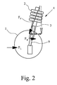
- Wheel suspension belong on the one hand with the body - not shown and on the other hand, a helical compression spring 2 connected to the wheel 1 and a shock absorber 3 having a shock absorber 4 and a wishbone 5.
- the helical compression spring force F F is not in the main load plane, a reaction force R F arises in the direction of travel. If the wishbone 5 were absolutely rigid, the component of the helical compression spring force F F acting in the direction of travel would be absorbed by the wishbone 5. In reality, however, the suspension is elastic overall; the control arm 5 and the steering, not shown in detail, are deformable. The component of the helical compression spring force F F acting in the direction of travel, the reaction force R F , is therefore only partially absorbed by the control arm 5, and in part it acts in the steering.
- a skewed course of the spring force action line 6 to the shock absorber center line 7 means that on the one hand the spring force action line 6 is skewed to project the spring center line 8 on the XZ plane, on the other hand runs obliquely to the projection of the spring center line 8 on the YZ plane.
- the spring force line of action 6 runs obliquely to the projection of the spring center line 8 on the XZ plane, transverse forces otherwise occurring on the shock absorber 3 or on the piston rod 9 of the shock absorber 3 are reduced, while the course of the spring force line of action 6 runs obliquely to the projection of the spring center line 8 the YZ plane reduces or minimizes or eliminates the forces which result from the difference between the components of the helical compression spring forces F F acting in the direction of travel on the left-hand side of the vehicle and on the right-hand side of the vehicle.
- the spring center line 8 of the helical compression spring 2 has an approximately S-shaped course in the unloaded state, on the one hand, and an approximately C-shaped course, on the other hand, in such a way that on the one hand, the spring force line of action 6 runs obliquely to the projection of the spring center line 8 on the XZ plane, on the other hand runs obliquely to the projection of the spring center line 8 on the YZ plane.
- the spring center line 8 of the helical compression spring 2 has an approximately S-shaped course in the unloaded state and the spring force line of action 6 runs obliquely for the projection of the spring center line 8 on the XZ plane, transverse forces otherwise occurring on the shock absorber 3 or on the piston rod 9 of the Shock absorber 3 reduced.
- Helical compression spring 2 is preferably designed so that by the helical compression spring 2 lateral forces are at least partially compensated for without the shear force compensating effect of the helical compression spring 2 am Shock absorber 3 appear.
- the helical compression spring 2 executed so that the spring center line 8 in the unloaded Condition has an approximately S-shaped course. This is in the illustrated Embodiment of the wheel suspension according to the invention also realizes the teaching that results from the German patent specification 37 43 450.
- the spring center line 8 of the helical compression spring 2 also has an approximately C-shaped course, as a result of which the force introduced into the steering, which results from the difference between the components of the helical compression spring forces F acting in the direction of travel F , that is, the reaction forces R F , on the left-hand side of the vehicle and the right-hand side of the vehicle results, is reduced or minimized or eliminated.
- a helical compression spring 2 can also be used to this extent, the spring center line of which has an approximately S-shaped course in the unloaded state.
- the invention is not only a wheel suspension of the previously described Rather, the subject of the invention is also a special one designed helical compression spring for use in a wheel suspension of the Art in question. Reference is made to claims 5 to 8.
Landscapes
- Engineering & Computer Science (AREA)
- Mechanical Engineering (AREA)
- Vehicle Body Suspensions (AREA)
- Springs (AREA)
Abstract
Description
- Fig. 1
- eine schematische Darstellung zu einer erfindungsgemäßen Radaufhängung, in Fahrzeuglängsrichtung gesehen,
- Fig. 2
- eine schematische Darstellung zu einer erfindungsgemäßen Radaufhängung, senkrecht zur Fahrzeuglängsrichtung gesehen, also von einer Fahrzeugseite aus,
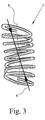
- Fig. 3
- eine Ansicht einer zu der erfindungsgemäßen Radaufhängung gehörenden Schraubendruckfeder, in Fahrzeuglängsrichtung gesehen, und
- Fig. 4
- eine Ansicht der Schraubendruckfeder nach Fig. 3, senkrecht zur Fahrzeuglängsrichtung gesehen, also von einer Fahrzeugseite.
Claims (8)
- Radaufhängung mit einem einerseits mit der Karosserie und andererseits mit dem Rad verbundenen, eine Schraubendruckfeder (= Tragfeder) und einen Stoßdämpfer aufweisenden, radführenden Federbein und mit einem Querlenker, wobei die Schraubendruckfeder vorzugsweise so gestaltet ist, daß durch die Schraubendruckfeder Querkräfte zumindest teilweise kompensiert werden, die ohne die querkraftkompensierende Wirkung der Schraubendruckfeder am Stoßdämpfer aufträten, dadurch gekennzeichnet, daß die Schraubendruckfeder (2) so gestaltet ist, daß die Federkraftwirkungslinie (6) windschief zur Stoßdämpfermittellinie (7) verläuft.
- Radaufhängung nach Anspruch 1, dadurch gekennzeichnet, daß zur zumindest teilweisen Kompensation der ansonsten am Stoßdämpfer (3) bzw. an der Kolbenstange (9) des Stoßdämpfers (3) auftretenden Querkräfte die Federmittellinie (8) der Schraubendruckfeder (2) im unbelasteten Zustand einen etwa S-förmigen Verlauf hat.
- Radaufhängung nach Anspruch 1 oder 2, dadurch gekennzeichnet, daß zur zumindest teilweisen Reduzierung der in die Lenkung eingeleiteten Kraft, die aus der Differenz zwischen den in Fahrtrichtung wirkenden Komponenten der Schraubendruckfederkräfte (FF), der Reaktionskräfte (RF), an der linken Fahrzeugseite und der rechten Fahrzeugseite resultiert, die Federmittellinie (8) der Schraubendruckfeder (2) im unbelasteten Zustand einen etwa C-förmigen Verlauf hat.
- Radaufhängung nach Anspruch 1 oder 2, dadurch gekennzeichnet, daß zur zumindest teilweisen Reduzierung der in die Lenkung eingeleiteten Kraft, die aus der Differenz zwischen den in Fahrtrichtung wirkenden Komponenten der Schraubendruckfederkräfte (FF), der Reaktionskräfte (RF), an der linken Fahrzeugseite und der rechten Fahrzeugseite resultiert, die Federmittellinie (8) der Schraubendruckfeder (2) im unbelasteten Zustand einen etwa S-förmigen Verlauf hat.
- Schraubendruckfeder für eine Radaufhängung mit einem einerseits mit der Karosserie und andererseits mit dem Rad (1) verbundenen, die Schraubendruckfeder (2) und einen Stoßdämpfer (3) aufweisenden, radführenden Federbein (4) und mit einem Querlenker (5), dadurch gekennzeichnet, daß sie so gestaltet ist, daß die Federkraftwirkungslinie (6) windschief zur Stoßdämpfermittellinie (7) verläuft.
- Schraubendruckfeder nach Anspruch 5, dadurch gekennzeichnet, daß die Federmittellinie (8) im unbelasteten Zustand einen etwa S-förmigen Verlauf hat.
- Schraubendruckfeder nach Anspruch 5 oder 6, dadurch gekennzeichnet, daß die Federmittellinie (8) im unbelasteten Zustand auch einen in einer anderen Ebene liegenden etwa C-förmigen Verlauf hat.
- Schraubendruckfeder nach Anspruch 5 oder 6, dadurch gekennzeichnet, daß die Federmittellinie (8) im unbelasteten Zustand auch einen in einer anderen Ebene liegenden etwa S-förmigen Verlauf hat.
Applications Claiming Priority (2)
| Application Number | Priority Date | Filing Date | Title |
|---|---|---|---|
| DE10125503A DE10125503C1 (de) | 2001-05-23 | 2001-05-23 | Radaufhängung |
| DE10125503 | 2001-05-23 |
Publications (3)
| Publication Number | Publication Date |
|---|---|
| EP1260390A2 true EP1260390A2 (de) | 2002-11-27 |
| EP1260390A3 EP1260390A3 (de) | 2004-10-06 |
| EP1260390B1 EP1260390B1 (de) | 2013-11-20 |
Family
ID=7686102
Family Applications (1)
| Application Number | Title | Priority Date | Filing Date |
|---|---|---|---|
| EP02005929.1A Revoked EP1260390B1 (de) | 2001-05-23 | 2002-03-15 | Aufhängungssystem mit einer Feder |
Country Status (4)
| Country | Link |
|---|---|
| US (1) | US6808193B2 (de) |
| EP (1) | EP1260390B1 (de) |
| DE (1) | DE10125503C1 (de) |
| ES (1) | ES2442850T3 (de) |
Cited By (3)
| Publication number | Priority date | Publication date | Assignee | Title |
|---|---|---|---|---|
| EP1839919A1 (de) * | 2006-03-30 | 2007-10-03 | Muhr und Bender KG | Schraubendruckfeder |
| EP2233329A1 (de) * | 2001-04-13 | 2010-09-29 | Mitsubishi Steel MFG. CO., LTD. | Aufhängungsspiralfeder |
| CN108202570A (zh) * | 2016-12-19 | 2018-06-26 | 本特勒汽车工业有限责任公司 | 用于车辆的车轮的车轮悬挂装置 |
Families Citing this family (16)
| Publication number | Priority date | Publication date | Assignee | Title |
|---|---|---|---|---|
| FR2860753B1 (fr) * | 2003-10-09 | 2007-07-27 | Allevard Rejna Autosuspensions | Suspension de vehicule |
| DE102004058698B3 (de) | 2004-12-06 | 2006-02-09 | Muhr Und Bender Kg | Radaufhängung mit Federverstellung für Kraftfahrzeuge |
| JP2006194427A (ja) | 2004-12-16 | 2006-07-27 | Yamaha Motor Co Ltd | スプリング用スペーサ、スプリング、サスペンション用スプリング、装置、サスペンション装置及び車両 |
| JP2006194428A (ja) * | 2004-12-16 | 2006-07-27 | Yamaha Motor Co Ltd | スプリング、サスペンション装置及び車両 |
| DE102006010052B4 (de) * | 2006-03-04 | 2016-07-07 | Bayerische Motoren Werke Aktiengesellschaft | Radaufhängung mit Federverstellung für ein Kraftfahrzeug |
| DE102006010055B4 (de) * | 2006-03-04 | 2014-07-31 | Bayerische Motoren Werke Aktiengesellschaft | Radaufhängung mit Federverstellung für ein Kraftfahrzeug |
| DE102006010054B4 (de) * | 2006-03-04 | 2014-08-28 | Bayerische Motoren Werke Aktiengesellschaft | Radaufhängung mit Federverstellung für ein Kraftfahrzeug |
| DE102007038072B4 (de) | 2006-12-18 | 2022-10-13 | Muhr Und Bender Kg | Radaufhängung |
| EP1935678A3 (de) | 2006-12-18 | 2010-04-14 | Muhr und Bender KG | Radaufhängung |
| EP1958803A3 (de) | 2007-02-15 | 2009-10-07 | Muhr und Bender KG | Radaufhängung |
| DE102007038070A1 (de) | 2007-02-15 | 2008-08-28 | Muhr Und Bender Kg | Radaufhängung |
| DE102008006411A1 (de) * | 2008-01-28 | 2009-07-30 | Muhr Und Bender Kg | Fahrzeugfeder aus Faserverbundwerkstoff |
| EP2374639B1 (de) * | 2010-04-12 | 2013-06-19 | Ford Global Technologies, LLC | Hinterradaufhängung deren Schraubenfeder eine geneigt angeordnete Kraftwirkungslinie aufweist |
| DE102015210850A1 (de) * | 2015-06-12 | 2016-12-15 | Ford Global Technologies, Llc | Radaufhängung für ein Kraftfahrzeug |
| US10471793B2 (en) | 2016-10-12 | 2019-11-12 | Ford Global Technologies, Llc | Seat mounts for side load spring on a twist beam axle |
| DE102024100253B4 (de) * | 2024-01-05 | 2026-03-26 | Thyssenkrupp Ag | Computerimplementiertes Verfahren zur Einstellung eines Kraftmittelpunkts oder einer Querkraft einer Schraubenfeder |
Citations (2)
| Publication number | Priority date | Publication date | Assignee | Title |
|---|---|---|---|---|
| DE1505616A1 (de) | 1966-07-22 | 1970-07-23 | Bayerische Motoren Werke Ag | Vorrichtung zur Geradfuehrung von unabhaengig aufgehaengten Raedern von Kraftfahrzeugen |
| EP0319651A2 (de) | 1987-12-08 | 1989-06-14 | Firma Muhr und Bender | Radaufhängung |
Family Cites Families (12)
| Publication number | Priority date | Publication date | Assignee | Title |
|---|---|---|---|---|
| US2942815A (en) * | 1956-04-19 | 1960-06-28 | Reinhold J Gross | Apparatus for retrieving objects descending by parachute |
| GB832669A (en) * | 1958-06-11 | 1960-04-13 | Ford Motor Co | Improvements in or relating to independent wheel suspensions |
| GB1152095A (en) * | 1967-02-07 | 1969-05-14 | Vauxhall Motors Ltd | Independent Wheel Suspension Assemblies for Motor Vehicles |
| DE3438591A1 (de) * | 1984-10-20 | 1986-02-27 | Daimler-Benz Ag, 7000 Stuttgart | Schraubenfeder, insbesondere schraubendruckfeder fuer kraftfahrzeug-radaufhaengungen |
| US5052664A (en) * | 1989-11-01 | 1991-10-01 | Barnes Group Inc. | Arcuate spring |
| DE4124326C1 (de) * | 1991-07-23 | 1992-04-16 | Krupp Brueninghaus Gmbh, 5980 Werdohl, De | |
| JP4162804B2 (ja) * | 1998-07-31 | 2008-10-08 | 中央発條株式会社 | ストラット型懸架装置 |
| JP3960710B2 (ja) * | 1998-07-31 | 2007-08-15 | 中央発條株式会社 | 自動車用懸架コイルばね |
| JP4601108B2 (ja) * | 2000-01-28 | 2010-12-22 | 中央発條株式会社 | 湾曲コイルばね及び該湾曲コイルばねの製造方法 |
| FR2804376A1 (fr) * | 2000-02-01 | 2001-08-03 | Michelin Ets | Methode de compensation du tirage d'un vehicule equipe de suspension mac pherson et jambe de force permettant cette compensation |
| JP2002178736A (ja) * | 2000-12-14 | 2002-06-26 | Chuo Spring Co Ltd | 自動車用懸架コイルばね及び該懸架コイルばねを備えたストラット型懸架装置 |
| US6481701B2 (en) * | 2001-03-09 | 2002-11-19 | Delphi Technologies, Inc. | Spring having coils of varying diameters |
-
2001
- 2001-05-23 DE DE10125503A patent/DE10125503C1/de not_active Revoked
-
2002
- 2002-03-15 EP EP02005929.1A patent/EP1260390B1/de not_active Revoked
- 2002-03-15 ES ES02005929.1T patent/ES2442850T3/es not_active Expired - Lifetime
- 2002-05-16 US US10/146,053 patent/US6808193B2/en not_active Expired - Lifetime
Patent Citations (3)
| Publication number | Priority date | Publication date | Assignee | Title |
|---|---|---|---|---|
| DE1505616A1 (de) | 1966-07-22 | 1970-07-23 | Bayerische Motoren Werke Ag | Vorrichtung zur Geradfuehrung von unabhaengig aufgehaengten Raedern von Kraftfahrzeugen |
| EP0319651A2 (de) | 1987-12-08 | 1989-06-14 | Firma Muhr und Bender | Radaufhängung |
| DE3743450A1 (de) | 1987-12-08 | 1989-06-29 | Muhr & Bender | Radaufhaengung |
Cited By (5)
| Publication number | Priority date | Publication date | Assignee | Title |
|---|---|---|---|---|
| EP2233329A1 (de) * | 2001-04-13 | 2010-09-29 | Mitsubishi Steel MFG. CO., LTD. | Aufhängungsspiralfeder |
| US7841088B2 (en) | 2001-04-13 | 2010-11-30 | Mitsubishi Steel Mfg. Co., Ltd. | Method of producing a suspension coil spring |
| US9783017B2 (en) | 2001-04-13 | 2017-10-10 | Mitsubishi Steel Mfg. Co., Ltd. | Suspension coil spring |
| EP1839919A1 (de) * | 2006-03-30 | 2007-10-03 | Muhr und Bender KG | Schraubendruckfeder |
| CN108202570A (zh) * | 2016-12-19 | 2018-06-26 | 本特勒汽车工业有限责任公司 | 用于车辆的车轮的车轮悬挂装置 |
Also Published As
| Publication number | Publication date |
|---|---|
| US6808193B2 (en) | 2004-10-26 |
| ES2442850T3 (es) | 2014-02-13 |
| EP1260390B1 (de) | 2013-11-20 |
| DE10125503C1 (de) | 2002-12-12 |
| EP1260390A3 (de) | 2004-10-06 |
| US20020175488A1 (en) | 2002-11-28 |
Similar Documents
| Publication | Publication Date | Title |
|---|---|---|
| EP1260390B1 (de) | Aufhängungssystem mit einer Feder | |
| DE3743450C2 (de) | ||
| DE69616415T2 (de) | Faltenbalg sowie Luftfeder-Aufhängungssystem und Achsanhebesystem | |
| DE60109115T2 (de) | Schraubendruckfeder für eine Fahrzeugradaufhängung | |
| DE102012107515B4 (de) | Aktives geometrie-gesteuertes aufhängungssystem | |
| DE102007038070A1 (de) | Radaufhängung | |
| WO2010085934A1 (de) | Querlenker eines kraftfahrzeuges | |
| DE102009047404A1 (de) | Radaufhängung | |
| EP1935678A2 (de) | Radaufhängung | |
| DE2915236A1 (de) | Aufhaengung fuer ein foerdermittel | |
| DE102005015089B4 (de) | Radaufhängung für ein Fahrzeug | |
| DE3938773C2 (de) | Federbein-Radaufhängung für Kraftfahrzeuge | |
| DE3743451A1 (de) | Radaufhaengung | |
| DE102007038072B4 (de) | Radaufhängung | |
| DE3741465C2 (de) | Stiftgelenkaufhängung eines Teleskopstoßdämpfers oder eines Federbeins für Kraftfahrzeuge | |
| DE102006057891B4 (de) | Wankstabilisierungs- und Wankdämpfungs-Anordnung für ein zweispuriges Fahrzeug | |
| EP0271690B1 (de) | Abstützung des Kastens eines Schienenfahrzeuges auf einem Drehgestell | |
| DE7505115U (de) | Als Geradführungselement in einer unabhängigen Radaufhängung verwendbarer Teleskopstoßdämpfer | |
| DE20221473U1 (de) | Radaufhängung | |
| DE3827760A1 (de) | Radfuehrende federbeinanordnung eines kraftfahrzeuges | |
| DE102011086887B4 (de) | Gefederte Abstützung für ein Fahrzeugrad | |
| DE3346307C2 (de) | Vorrichtung zur Begrenzung von Wankbewegungen eines Schienenfahrzeugs mit wiegenlosen Luftfederdrehgestellen | |
| DE4126501C2 (de) | Radaufhängung eines Kraftfahrzeugs | |
| DE102016124870A1 (de) | Radaufhängung für ein Rad eines Fahrzeugs | |
| DE2924368A1 (de) | Einzelradaufhaengung fuer kraftfahrzeuge |
Legal Events
| Date | Code | Title | Description |
|---|---|---|---|
| PUAI | Public reference made under article 153(3) epc to a published international application that has entered the european phase |
Free format text: ORIGINAL CODE: 0009012 |
|
| AK | Designated contracting states |
Kind code of ref document: A2 Designated state(s): AT BE CH CY DE DK ES FI FR GB GR IE IT LI LU MC NL PT SE TR |
|
| AX | Request for extension of the european patent |
Free format text: AL;LT;LV;MK;RO;SI |
|
| PUAL | Search report despatched |
Free format text: ORIGINAL CODE: 0009013 |
|
| AK | Designated contracting states |
Kind code of ref document: A3 Designated state(s): AT BE CH CY DE DK ES FI FR GB GR IE IT LI LU MC NL PT SE TR |
|
| AX | Request for extension of the european patent |
Extension state: AL LT LV MK RO SI |
|
| 17P | Request for examination filed |
Effective date: 20041112 |
|
| AKX | Designation fees paid |
Designated state(s): AT BE CH CY DE DK ES FI FR GB GR IE IT LI LU MC NL PT SE TR |
|
| GRAP | Despatch of communication of intention to grant a patent |
Free format text: ORIGINAL CODE: EPIDOSNIGR1 |
|
| RIC1 | Information provided on ipc code assigned before grant |
Ipc: F16F 1/04 20060101ALI20130607BHEP Ipc: B60G 3/06 20060101ALI20130607BHEP Ipc: B60G 15/06 20060101ALI20130607BHEP Ipc: B60G 11/14 20060101AFI20130607BHEP |
|
| INTG | Intention to grant announced |
Effective date: 20130628 |
|
| GRAS | Grant fee paid |
Free format text: ORIGINAL CODE: EPIDOSNIGR3 |
|
| GRAA | (expected) grant |
Free format text: ORIGINAL CODE: 0009210 |
|
| AK | Designated contracting states |
Kind code of ref document: B1 Designated state(s): AT BE CH CY DE DK ES FI FR GB GR IE IT LI LU MC NL PT SE TR |
|
| REG | Reference to a national code |
Ref country code: GB Ref legal event code: FG4D Free format text: NOT ENGLISH |
|
| REG | Reference to a national code |
Ref country code: CH Ref legal event code: EP |
|
| REG | Reference to a national code |
Ref country code: AT Ref legal event code: REF Ref document number: 641366 Country of ref document: AT Kind code of ref document: T Effective date: 20131215 |
|
| REG | Reference to a national code |
Ref country code: IE Ref legal event code: FG4D Free format text: LANGUAGE OF EP DOCUMENT: GERMAN |
|
| REG | Reference to a national code |
Ref country code: DE Ref legal event code: R096 Ref document number: 50215855 Country of ref document: DE Effective date: 20140109 |
|
| REG | Reference to a national code |
Ref country code: ES Ref legal event code: FG2A Ref document number: 2442850 Country of ref document: ES Kind code of ref document: T3 Effective date: 20140213 |
|
| REG | Reference to a national code |
Ref country code: NL Ref legal event code: VDEP Effective date: 20131120 |
|
| PG25 | Lapsed in a contracting state [announced via postgrant information from national office to epo] |
Ref country code: FI Free format text: LAPSE BECAUSE OF FAILURE TO SUBMIT A TRANSLATION OF THE DESCRIPTION OR TO PAY THE FEE WITHIN THE PRESCRIBED TIME-LIMIT Effective date: 20131120 Ref country code: NL Free format text: LAPSE BECAUSE OF FAILURE TO SUBMIT A TRANSLATION OF THE DESCRIPTION OR TO PAY THE FEE WITHIN THE PRESCRIBED TIME-LIMIT Effective date: 20131120 Ref country code: SE Free format text: LAPSE BECAUSE OF FAILURE TO SUBMIT A TRANSLATION OF THE DESCRIPTION OR TO PAY THE FEE WITHIN THE PRESCRIBED TIME-LIMIT Effective date: 20131120 |
|
| PG25 | Lapsed in a contracting state [announced via postgrant information from national office to epo] |
Ref country code: PT Free format text: LAPSE BECAUSE OF FAILURE TO SUBMIT A TRANSLATION OF THE DESCRIPTION OR TO PAY THE FEE WITHIN THE PRESCRIBED TIME-LIMIT Effective date: 20140320 |
|
| REG | Reference to a national code |
Ref country code: DE Ref legal event code: R026 Ref document number: 50215855 Country of ref document: DE |
|
| PLBI | Opposition filed |
Free format text: ORIGINAL CODE: 0009260 |
|
| PG25 | Lapsed in a contracting state [announced via postgrant information from national office to epo] |
Ref country code: DK Free format text: LAPSE BECAUSE OF FAILURE TO SUBMIT A TRANSLATION OF THE DESCRIPTION OR TO PAY THE FEE WITHIN THE PRESCRIBED TIME-LIMIT Effective date: 20131120 |
|
| PLAX | Notice of opposition and request to file observation + time limit sent |
Free format text: ORIGINAL CODE: EPIDOSNOBS2 |
|
| 26 | Opposition filed |
Opponent name: THYSSENKRUPP AG Effective date: 20140820 |
|
| PG25 | Lapsed in a contracting state [announced via postgrant information from national office to epo] |
Ref country code: LU Free format text: LAPSE BECAUSE OF FAILURE TO SUBMIT A TRANSLATION OF THE DESCRIPTION OR TO PAY THE FEE WITHIN THE PRESCRIBED TIME-LIMIT Effective date: 20140315 |
|
| REG | Reference to a national code |
Ref country code: CH Ref legal event code: PL |
|
| REG | Reference to a national code |
Ref country code: DE Ref legal event code: R026 Ref document number: 50215855 Country of ref document: DE Effective date: 20140820 |
|
| GBPC | Gb: european patent ceased through non-payment of renewal fee |
Effective date: 20140315 |
|
| REG | Reference to a national code |
Ref country code: IE Ref legal event code: MM4A |
|
| PG25 | Lapsed in a contracting state [announced via postgrant information from national office to epo] |
Ref country code: CH Free format text: LAPSE BECAUSE OF NON-PAYMENT OF DUE FEES Effective date: 20140331 Ref country code: IE Free format text: LAPSE BECAUSE OF NON-PAYMENT OF DUE FEES Effective date: 20140315 Ref country code: LI Free format text: LAPSE BECAUSE OF NON-PAYMENT OF DUE FEES Effective date: 20140331 Ref country code: GB Free format text: LAPSE BECAUSE OF NON-PAYMENT OF DUE FEES Effective date: 20140315 |
|
| PLBB | Reply of patent proprietor to notice(s) of opposition received |
Free format text: ORIGINAL CODE: EPIDOSNOBS3 |
|
| REG | Reference to a national code |
Ref country code: AT Ref legal event code: MM01 Ref document number: 641366 Country of ref document: AT Kind code of ref document: T Effective date: 20140315 |
|
| PG25 | Lapsed in a contracting state [announced via postgrant information from national office to epo] |
Ref country code: AT Free format text: LAPSE BECAUSE OF NON-PAYMENT OF DUE FEES Effective date: 20140315 |
|
| REG | Reference to a national code |
Ref country code: FR Ref legal event code: PLFP Year of fee payment: 15 |
|
| PGFP | Annual fee paid to national office [announced via postgrant information from national office to epo] |
Ref country code: ES Payment date: 20160222 Year of fee payment: 15 Ref country code: DE Payment date: 20160304 Year of fee payment: 15 Ref country code: IT Payment date: 20160224 Year of fee payment: 15 |
|
| PLAB | Opposition data, opponent's data or that of the opponent's representative modified |
Free format text: ORIGINAL CODE: 0009299OPPO |
|
| PG25 | Lapsed in a contracting state [announced via postgrant information from national office to epo] |
Ref country code: MC Free format text: LAPSE BECAUSE OF FAILURE TO SUBMIT A TRANSLATION OF THE DESCRIPTION OR TO PAY THE FEE WITHIN THE PRESCRIBED TIME-LIMIT Effective date: 20131120 |
|
| PGFP | Annual fee paid to national office [announced via postgrant information from national office to epo] |
Ref country code: FR Payment date: 20160216 Year of fee payment: 15 |
|
| R26 | Opposition filed (corrected) |
Opponent name: THYSSENKRUPP AG Effective date: 20140820 |
|
| PG25 | Lapsed in a contracting state [announced via postgrant information from national office to epo] |
Ref country code: GR Free format text: LAPSE BECAUSE OF FAILURE TO SUBMIT A TRANSLATION OF THE DESCRIPTION OR TO PAY THE FEE WITHIN THE PRESCRIBED TIME-LIMIT Effective date: 20140221 Ref country code: CY Free format text: LAPSE BECAUSE OF FAILURE TO SUBMIT A TRANSLATION OF THE DESCRIPTION OR TO PAY THE FEE WITHIN THE PRESCRIBED TIME-LIMIT Effective date: 20131120 |
|
| PG25 | Lapsed in a contracting state [announced via postgrant information from national office to epo] |
Ref country code: TR Free format text: LAPSE BECAUSE OF FAILURE TO SUBMIT A TRANSLATION OF THE DESCRIPTION OR TO PAY THE FEE WITHIN THE PRESCRIBED TIME-LIMIT Effective date: 20131120 Ref country code: BE Free format text: LAPSE BECAUSE OF FAILURE TO SUBMIT A TRANSLATION OF THE DESCRIPTION OR TO PAY THE FEE WITHIN THE PRESCRIBED TIME-LIMIT Effective date: 20140331 |
|
| REG | Reference to a national code |
Ref country code: DE Ref legal event code: R064 Ref document number: 50215855 Country of ref document: DE Ref country code: DE Ref legal event code: R103 Ref document number: 50215855 Country of ref document: DE |
|
| RDAF | Communication despatched that patent is revoked |
Free format text: ORIGINAL CODE: EPIDOSNREV1 |
|
| STAA | Information on the status of an ep patent application or granted ep patent |
Free format text: STATUS: THE PATENT HAS BEEN GRANTED |
|
| RDAG | Patent revoked |
Free format text: ORIGINAL CODE: 0009271 |
|
| 27W | Patent revoked |
Effective date: 20170214 |
|
| REG | Reference to a national code |
Ref country code: AT Ref legal event code: MA03 Ref document number: 641366 Country of ref document: AT Kind code of ref document: T Effective date: 20170214 |
|
| STAA | Information on the status of an ep patent application or granted ep patent |
Free format text: STATUS: PATENT REVOKED |