EP1260452A2 - Kabelbinder mit breitem Hals - Google Patents
Kabelbinder mit breitem Hals Download PDFInfo
- Publication number
- EP1260452A2 EP1260452A2 EP02253462A EP02253462A EP1260452A2 EP 1260452 A2 EP1260452 A2 EP 1260452A2 EP 02253462 A EP02253462 A EP 02253462A EP 02253462 A EP02253462 A EP 02253462A EP 1260452 A2 EP1260452 A2 EP 1260452A2
- Authority
- EP
- European Patent Office
- Prior art keywords
- strap
- cable tie
- width
- neck
- neck section
- Prior art date
- Legal status (The legal status is an assumption and is not a legal conclusion. Google has not performed a legal analysis and makes no representation as to the accuracy of the status listed.)
- Granted
Links
- 230000002829 reductive effect Effects 0.000 claims abstract description 18
- 230000007704 transition Effects 0.000 claims abstract description 11
- 238000000034 method Methods 0.000 claims description 9
- 239000000463 material Substances 0.000 claims description 8
- 239000012530 fluid Substances 0.000 claims 1
- 238000005452 bending Methods 0.000 description 7
- 230000008901 benefit Effects 0.000 description 7
- 230000036961 partial effect Effects 0.000 description 7
- 230000003247 decreasing effect Effects 0.000 description 5
- 238000000465 moulding Methods 0.000 description 5
- 239000002184 metal Substances 0.000 description 4
- 230000008859 change Effects 0.000 description 3
- 238000004519 manufacturing process Methods 0.000 description 2
- 239000004033 plastic Substances 0.000 description 2
- 230000009467 reduction Effects 0.000 description 2
- 239000004677 Nylon Substances 0.000 description 1
- 239000004743 Polypropylene Substances 0.000 description 1
- 229910000831 Steel Inorganic materials 0.000 description 1
- 230000002411 adverse Effects 0.000 description 1
- 230000000694 effects Effects 0.000 description 1
- 230000002349 favourable effect Effects 0.000 description 1
- 239000004811 fluoropolymer Substances 0.000 description 1
- 229920002313 fluoropolymer Polymers 0.000 description 1
- 238000001746 injection moulding Methods 0.000 description 1
- 238000009413 insulation Methods 0.000 description 1
- 230000000670 limiting effect Effects 0.000 description 1
- 238000012986 modification Methods 0.000 description 1
- 230000004048 modification Effects 0.000 description 1
- 229920001778 nylon Polymers 0.000 description 1
- -1 polypropylene Polymers 0.000 description 1
- 229920001155 polypropylene Polymers 0.000 description 1
- 229910001220 stainless steel Inorganic materials 0.000 description 1
- 239000010935 stainless steel Substances 0.000 description 1
- 239000010959 steel Substances 0.000 description 1
Images




Classifications
-
- B—PERFORMING OPERATIONS; TRANSPORTING
- B65—CONVEYING; PACKING; STORING; HANDLING THIN OR FILAMENTARY MATERIAL
- B65D—CONTAINERS FOR STORAGE OR TRANSPORT OF ARTICLES OR MATERIALS, e.g. BAGS, BARRELS, BOTTLES, BOXES, CANS, CARTONS, CRATES, DRUMS, JARS, TANKS, HOPPERS, FORWARDING CONTAINERS; ACCESSORIES, CLOSURES, OR FITTINGS THEREFOR; PACKAGING ELEMENTS; PACKAGES
- B65D63/00—Flexible elongated elements, e.g. straps, for bundling or supporting articles
- B65D63/10—Non-metallic straps, tapes, or bands; Filamentary elements, e.g. strings, threads or wires; Joints between ends thereof
- B65D63/1018—Joints produced by application of integral securing members, e.g. buckles, wedges, tongue and slot, locking head and teeth or the like
- B65D63/1027—Joints produced by application of integral securing members, e.g. buckles, wedges, tongue and slot, locking head and teeth or the like the integral securing member being formed as a female and male locking member, e.g. locking head and locking teeth, or the like
- B65D63/1036—Joints produced by application of integral securing members, e.g. buckles, wedges, tongue and slot, locking head and teeth or the like the integral securing member being formed as a female and male locking member, e.g. locking head and locking teeth, or the like the female locking member being provided with at least one metal barb
-
- Y—GENERAL TAGGING OF NEW TECHNOLOGICAL DEVELOPMENTS; GENERAL TAGGING OF CROSS-SECTIONAL TECHNOLOGIES SPANNING OVER SEVERAL SECTIONS OF THE IPC; TECHNICAL SUBJECTS COVERED BY FORMER USPC CROSS-REFERENCE ART COLLECTIONS [XRACs] AND DIGESTS
- Y10—TECHNICAL SUBJECTS COVERED BY FORMER USPC
- Y10T—TECHNICAL SUBJECTS COVERED BY FORMER US CLASSIFICATION
- Y10T24/00—Buckles, buttons, clasps, etc.
- Y10T24/14—Bale and package ties, hose clamps
- Y10T24/1498—Plastic band
-
- Y—GENERAL TAGGING OF NEW TECHNOLOGICAL DEVELOPMENTS; GENERAL TAGGING OF CROSS-SECTIONAL TECHNOLOGIES SPANNING OVER SEVERAL SECTIONS OF THE IPC; TECHNICAL SUBJECTS COVERED BY FORMER USPC CROSS-REFERENCE ART COLLECTIONS [XRACs] AND DIGESTS
- Y10—TECHNICAL SUBJECTS COVERED BY FORMER USPC
- Y10T—TECHNICAL SUBJECTS COVERED BY FORMER US CLASSIFICATION
- Y10T24/00—Buckles, buttons, clasps, etc.
- Y10T24/15—Bag fasteners
- Y10T24/153—Plastic band bag tie
Definitions
- the present invention relates generally to an advanced neck design for cable ties.
- Cable ties have traditionally been formed by an integral molding of a cable tie head and a cable strap. Most of these cable ties involve a design in which the elongated strap extends straight outward from the cable tie head.
- An example of such a conventional cable tie design is U.S. Patent No. 3,949,449 to Caveney et al., which is represented in Figs. 1-3.
- this conventional cable tie 100 includes an elongated strap 110 extending from an integrally molded cable tie head 120.
- a neck area 130 is formed at the interface between strap 110 and head 120.
- Cable tie head 120 includes a strap accepting channel 140 that receives strap 110 and a locking device 150, In use, cable tie 100 can be wrapped around objects such as a bundle of cables 160 and locked in place as known in the art.
- cable tie 100 is again integrally formed with both a cable tie head 120 and a strap 110.
- strap 110 initially extends from head 120 along a strap attachment axis S substantially parallel to the strap passageway, and is then formed with a bend at neck section 130 such that the strap extends substantially perpendicular to the strap attachment axis S.
- Figs. 4-9 substantially conforms to the conventionally used notion that the neck should correspond in size to the strap. That is, strap 110 has a substantially constant overall width and thickness.
- Neck section 130 in this design has substantially the same width B as the strap 110 and may include a cored out bottom portion 115 that has a reduced thickness at central portions as best shown in Fig. 7. This reduction in thickness is used to increase flexibility in the neck area.
- Molding in such a design is achieved by a two-piece mold having a complex shape.
- the mold has a stepped part line (P/L) as shown with the bolded dashed line in Figs. 6 and 8 in which the part line follows the midline of strap 110 around the bend of neck section 130 where the part line then angles down across cable tie head 120.
- P/L stepped part line
- the part line follows the midline of strap 110 around the bend of neck section 130 where the part line then angles down across cable tie head 120.
- the simplest mold tooling design of a cable tie head 120 that has a width E substantially larger than the width B at the neck area (Fig. 4)
- This sharp edge and mismatch can be avoided with complicated tooling, including the complicated metal mold 200 partially shown in Fig. 8.
- Such complicated tooling has sharp edges that could be easily worn or broken.
- neck section 130 For either design there is a sharp step (change in cross-section) from the transition of neck section 130 to cable tie head 120, there is a distinct potential for stress risers. As the neck section bends considerably in either direction, such stress risers can lead to part failures, particularly when brittle materials are used for the part.
- the neck design allows improved flexibility and bending at the neck without reducing loop strength from that attained in the strap section. Moreover, the neck design maintains a generous edge radius that prevents cable insulation damage and allows use of a simpler mold design.
- Applicants have found that the lie of a strap in a bent neck type cable tie can be improved by maximizing the radius of the neck at the bend and by improving the neck's flexibility.
- the strap thickness, parting line angle, and strap body edge radii limit the size of the radii that can transition from cable tie head to neck.
- the flexibility of the neck can be improved by: 1) making the strap narrower; or 2) making the strap thinner. Reducing either variable and holding the other constant would reduce the moment of inertia and thereby decrease the force to bend the part in that region. However, doing so will also decrease the area through the section (A ⁇ B x T), which has the adverse effect of decreasing tensile strength through the section. As such, attempts to increase bending flexibility using these methods would result in reduced tensile strength, which is undesirable.
- Applicants have noted that by increasing the width of the strap while decreasing the thickness, one can achieve a desired lower moment of inertia while maintaining or increasing the tensile strength (area) of the section.
- the magnitude of the moment of inertia can be decreased as the strap width increases by reducing the overall thickness of the part, or by creating a channel on either or both sides of the part.
- the channel-shaped geometry has the added advantage that a larger thickness flow path is maintained for the purpose of more easily filling out a molded part,
- Applicants have also found manufacturing and use advantages to increasing of the width of the strap to match the width of the cable tie head.
- This provides the most desirable tooling configuration for a stepped parting line part, which may be used to create bent neck type cable ties such as those of the claimed invention. That is, a neck width that matches the head width eliminates the need for weak or complicated mold components to eliminate sharp edges or mismatches on the part.
- Such a design in which a neck width matches the head width also eliminates a traditional stress concentration where there is an abrupt change in cross-section.
- a cable tie that includes an integral cable tie head and strap.
- the strap includes a first end forming a neck section, a free end opposite the first end, and an intermediate section between the first end and the free end, the intermediate section having a predetermined width B 1 and thickness T 1 defining a predetermined cross-sectional area.
- the cable tie head is secured to the neck area of the strap at the first end of the strap, the cable tie head having a width E that is wider than strap width B and including a strap accepting channel containing a locking device.
- the strap accepting channel is sized to receive the free end of the strap.
- the neck section has a width that transitions from a width of B to a width E' that is substantially the same as width E and a thickness T 2 that is thinner than T 1 , the neck section having a cross-sectional area that is at least substantially equal to the cross-sectional area of the intermediate section of the strap so as to have a tensile strength at least equal to a tensile strength of the intermediate section of the strap.
- the cable tie may be a bent neck type cable tie.
- the neck section has at least one recessed channel defining the reduced thickness T 2 and thickened side portions.
- the invention relates to a cable tie having improved flexibility at a neck section of the cable tie, which is particularly important in a bent neck type cable tie.
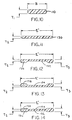
- Conventional cable ties primarily use neck cross-sections that substantially correspond to the cross-section of the strap (see Fig. 10). While this results in a neck section that has a tensile strength equal to the rest of the strap, it results in the previously described problems of bent neck cable ties with a stepped parting line.
- the strap thickness, parting line angle, and strap body edge radii limit the size of the radii that can transition from cable tie head to neck in a bent neck type cable tie.
- the general equation for the moment of inertia for a simple rectangular cross-section cable tie is I ⁇ (B x T 3 )/12 where B is the width of the strap and T is the thickness of the strap.
- the design of Figs. 8-9 results in a neck with limited flexibility as the neck cross-section is approximately the same as the cross-section of the strap body (shown in Fig. 10), which has a high moment of inertia. While the flexibility can be increased by the provision of a cored out bottom portion 115, this results in a reduction of tensile strength from that attained at the strap, which may be undesirable.
- the lie of the strap can be improved.
- the magnitude of the moment of inertia can be decreased as the strap width increases by reducing the overall thickness of the part, or by creating a reduced thickness channel on either or both sides of the part.
- the channel-shaped geometry has the added advantage that a larger thickness flow path (greater cross-sectional area) is maintained for the purpose of more easily filling out a molded part.
- Figs. 11-14 Exemplary cross-sectional designs that can be used to achieve this result are shown in Figs. 11-14.
- the cross-sectional area at the neck can remain substantially the same as the area of the Strap (Fig. 10), but results in a lower moment of inertia than that at the strap body to allow better flexibility in the neck area while retaining sufficient tensile strength.
- the neck region 130 of the strap 110 is both wider than narrower than the strap, while having substantially the same cross-sectional area as the strap cross-section.
- a channel region 132 is cut from the lower surface of the strap so as to define a reduced thickness center portion (thickness T 2 ) and side portions 136 having thickness T 3 .
- a channel region 134 is cut from the upper surface of the strap so as to define a reduced thickness center portion (thickness T 2 ) and increased thickness side portions 138 similar to that in Fig. 12.
- both channels 132 and 134 are provided.
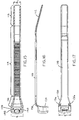
- FIG. 15-19 A first exemplary bent neck type cable tie incorporating these principles is shown in Figs. 15-19.
- These cable ties are molded from various materials, such as nylon, polypropylene, and other various fluoropolymers. Such cable ties can be molded in various sizes and lengths to suit a particular application as also known in the art. Moreover, these cable ties can be either one-piece or two-piece cable ties having either an integral locking device or a separate metal locking device as known in the art.
- This exemplary cable tie 100 includes a cable tie strap 110 having a first end forming a neck section 130, an intermediate section 114 of a substantially uniform width B, and a free end 112.
- the first end (neck section 130) of strap 110 is molded to a cable tie head 120 having a substantially constant width E.
- Neck section 130 transitions from the narrower strap width B to a width E' that is substantially the same as the width of cable tie head 120.
- Cable tie 100 also includes a strap accepting channel 140 having a strap locking device 150.
- Locking device 150 either is a unitary member (one-piece cable tie) that mates with one or more teeth 116 provided on strap 110 or is a separate metal locking device formed of a material such as stainless steel that bites into the softer strap material to hold the strap in place and resist removal.
- neck section 130 tapers to substantially match the outer contour and width E of the cable head 120.
- Neck section 130 in this embodiment has a cross-section similar to the one shown in Fig. 14, in which both an upper groove 134 and a lower groove 132 are formed in the neck section to provide a reduced thickness compared to thickened side portions 136 and 138 which may have a thickness substantially the same as the thickness of the intermediate section of strap 110.
- the width of neck section 130 has increased from a width B to a width of E', the total cross-sectional area at a point of flexure is substantially the same as strap 110.
- the neck section 130 can achieve the same or even better tensile strength as the strap 110 itself while improving flexibility at neck section 130 by lowering the moment of inertia. This is important in a bent neck type cable tie as the bending forces during flexure of the cable tie are concentrated at neck section 130.
- Applicants have also found manufacturing advantages to increasing the width of the strap at the neck section to match the width of the cable tie head. This provides the most desirable tooling configuration for a stepped parting line part, which can be used to create bent neck type cable ties such as those of the claimed invention. Moreover, by provision of the thickened side portions 136 and 138, a larger flow path is provided between the cable tie head and strap for the purpose and advantage of more readily filling a molded part during molding. This is helpful in assuring adequate material flow during injection molding through the neck section 130, which due to the reduced thickness may otherwise prevent adequate material flow to achieve reliable and consistent molding.
- a neck width that matches the head width eliminates the need for weak or complicated mold components that could wear or break to eliminate mismatch and sharp comers on the plastic part.
- Such a design in which a neck width matches the head width also eliminates a traditional stress concentration where there is an abrupt change in cross-section.
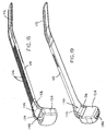
- neck section 130 also transitions from a width of B to a width E' that is substantially the same as the width E of cable tie head 120.
- neck section 130 has a cross-section similar to that shown in Fig. 12 in which a cored out channel 132 is formed on the lower side only, leaving thickened side portions 136 on the lower side. This results in a lower moment of inertia.
- the channel 132 expands in width toward cable tie head 120 as shown in Figs. 21 and 25 so that a substantially constant total cross-sectional area can be provided along the length of neck section 130 to maintain a desired tensile strength while increasing flexibility toward the first end of strap 110.
- cable tie 100 is formed by a two-piece mold having a stepped part line (P/L) as shown in dashed line form.
- This part line P/L follows the midline of strap 110 around the bend of neck section 130 where the part line then angles down across cable head 120.
- This part line P/L follows the midline of strap 110 around the bend of neck section 130 where the part line then angles down across cable head 120.
Landscapes
- Engineering & Computer Science (AREA)
- Mechanical Engineering (AREA)
- Package Frames And Binding Bands (AREA)
- Installation Of Indoor Wiring (AREA)
- Basic Packing Technique (AREA)
- Supports For Pipes And Cables (AREA)
Applications Claiming Priority (2)
| Application Number | Priority Date | Filing Date | Title |
|---|---|---|---|
| US09/855,917 US6745439B2 (en) | 2001-05-15 | 2001-05-15 | Cable tie with wide neck |
| US855917 | 2001-05-15 |
Publications (3)
| Publication Number | Publication Date |
|---|---|
| EP1260452A2 true EP1260452A2 (de) | 2002-11-27 |
| EP1260452A3 EP1260452A3 (de) | 2003-03-05 |
| EP1260452B1 EP1260452B1 (de) | 2006-04-26 |
Family
ID=25322426
Family Applications (1)
| Application Number | Title | Priority Date | Filing Date |
|---|---|---|---|
| EP02253462A Expired - Lifetime EP1260452B1 (de) | 2001-05-15 | 2002-05-15 | Kabelbinder mit breitem Hals |
Country Status (5)
| Country | Link |
|---|---|
| US (2) | US6745439B2 (de) |
| EP (1) | EP1260452B1 (de) |
| JP (1) | JP4278344B2 (de) |
| CN (1) | CN1288042C (de) |
| DE (1) | DE60210860T2 (de) |
Cited By (3)
| Publication number | Priority date | Publication date | Assignee | Title |
|---|---|---|---|---|
| EP2530028A1 (de) * | 2011-06-03 | 2012-12-05 | Daiwa Kasei Industry Co., Ltd. | Riemenklammer |
| EP1843070A3 (de) * | 2006-04-05 | 2016-03-02 | Thomas & Betts International, Inc. | Auffindbarer Kabelbinder |
| EP3656696A1 (de) * | 2018-11-20 | 2020-05-27 | HellermannTyton GmbH | Kabelbinder, verfahren zur herstellung eines kabelbinders und kabelbinderspritzgiesswerkzeug |
Families Citing this family (28)
| Publication number | Priority date | Publication date | Assignee | Title |
|---|---|---|---|---|
| US6745439B2 (en) | 2001-05-15 | 2004-06-08 | Panduit Corp. | Cable tie with wide neck |
| ITPD20010111U1 (it) * | 2001-11-27 | 2003-05-27 | Llxan Internat Srl Unipersonal | Dispositivo antifurto perfezionato per oggetti dotati di porzioni circondabili da fascette o simili |
| USD493355S1 (en) | 2003-10-23 | 2004-07-27 | Thomas & Betts International, Inc. | Plurality of coupled cable tie heads |
| USD530600S1 (en) | 2004-10-18 | 2006-10-24 | Panduit Corp. | Cable tie |
| USD541142S1 (en) | 2004-11-01 | 2007-04-24 | Hellermanntyton Corporation | Element of a cable tie strap |
| US7651169B2 (en) * | 2005-04-07 | 2010-01-26 | French Components Corporation | Strap retainer for shopping cart seatbelts |
| US7779515B2 (en) * | 2005-05-13 | 2010-08-24 | Panduit Corp. | Two-piece cable tie suitable for use in an automated cable tie installation tool |
| US7753320B2 (en) * | 2005-07-28 | 2010-07-13 | Hellermanntyton Corporation | Flush mount connector clip |
| US20070023586A1 (en) * | 2005-07-28 | 2007-02-01 | Hellermann Tyton Corporation | Harness clamp tie |
| AU2007317178B2 (en) * | 2006-11-09 | 2013-02-28 | Caterpillar Global Mining Expanded Products Pty Ltd | A fastener retaining device |
| US7774905B2 (en) * | 2007-02-14 | 2010-08-17 | Hellermanntyton Corporation | Element of a cable tie strap |
| US20090106948A1 (en) * | 2007-10-26 | 2009-04-30 | Lopez Joseph V | Method and apparatus for retaining elongated flexible articles including visual inspection apparatus inspection probes |
| US7866005B2 (en) | 2008-01-09 | 2011-01-11 | Panduit Corp. | Elastomeric releasable cable tie |
| US8726468B2 (en) * | 2009-03-18 | 2014-05-20 | Hellermanntyton Corporation | Bundle tie with head dampener |
| US8496864B2 (en) | 2010-03-16 | 2013-07-30 | The John Hopkins University | Static dissipative cable ties, such as for radiation belt storm probes |
| JP5478374B2 (ja) * | 2010-06-15 | 2014-04-23 | ポップリベット・ファスナー株式会社 | 結束具 |
| AU338009S (en) * | 2010-12-01 | 2011-08-10 | Illinois Tool Works | Pipe clamp |
| JP2012137145A (ja) * | 2010-12-27 | 2012-07-19 | Daiwa Kasei Kogyo Kk | ベルトクランプ |
| SE538496C2 (en) * | 2014-07-11 | 2016-08-09 | Resorbable Devices Ab | Cable tie based medical device |
| USD799125S1 (en) * | 2015-03-25 | 2017-10-03 | Aaron + Amanda Holdings, Inc. | Animal identification band |
| JP1548650S (de) * | 2015-06-24 | 2019-04-15 | ||
| US10683150B2 (en) * | 2016-01-13 | 2020-06-16 | Thomas & Betts International Llc | High performance, dual materials cable-tie head |
| CN106123782B (zh) * | 2016-06-16 | 2019-01-22 | 中达电通股份有限公司 | 扎带基座装配系统和方法以及扎带基座装配检测系统 |
| US10435214B2 (en) | 2017-01-04 | 2019-10-08 | Brian Kuperus | Tie-wrap assembly and method for using the same |
| US12326210B2 (en) | 2022-03-24 | 2025-06-10 | Hellermanntyton Corporation | Quick attach clamp |
| US12338848B2 (en) | 2022-06-30 | 2025-06-24 | Hellermanntyton Corporation | Anti-wobble fir tree mount |
| US12351375B2 (en) | 2023-02-28 | 2025-07-08 | Brian Kuperus | Ligation assembly and method for using the same |
| US20240360922A1 (en) | 2023-04-28 | 2024-10-31 | Hellermanntyton Corporation | Cable Tie Cradle Mount Fixings |
Citations (1)
| Publication number | Priority date | Publication date | Assignee | Title |
|---|---|---|---|---|
| US3949449A (en) | 1969-04-09 | 1976-04-13 | Panduit Corporation | Integral one-piece cable tie |
Family Cites Families (31)
| Publication number | Priority date | Publication date | Assignee | Title |
|---|---|---|---|---|
| US3186047A (en) | 1962-08-14 | 1965-06-01 | Thomas & Betts Corp | Self clinching bundling strap |
| DE1275650B (de) | 1967-03-03 | 1968-08-22 | Hellermann Gmbh P | Kabelbindevorrichtung |
| US3408699A (en) | 1967-08-07 | 1968-11-05 | Thomas & Betts Corp | Bundling strap |
| US3486200A (en) | 1968-07-23 | 1969-12-30 | Emil H Orenick | Cable strap |
| US3457598A (en) | 1968-08-09 | 1969-07-29 | Thomas & Betts Corp | Self-clinching bundling strap |
| US3488813A (en) | 1968-08-22 | 1970-01-13 | Thomas & Betts Corp | Bundling strap |
| US3735448A (en) * | 1970-02-25 | 1973-05-29 | Buchanan Electrical Prod Corp | Wire tie |
| US4001898A (en) * | 1975-10-06 | 1977-01-11 | Panduit Corporation | Fixed dog ladder strap |
| US4495972A (en) | 1980-02-27 | 1985-01-29 | Bowthorpe-Hellermann Limited | Automatic tie gun |
| US4473524A (en) * | 1980-02-28 | 1984-09-25 | Paradis Joseph R | Method for molding and stretching a harnessing device |
| US4658478A (en) * | 1980-07-14 | 1987-04-21 | Dennison Manufacturing Company | Bundling of objects |
| DE3049066A1 (de) * | 1980-12-24 | 1982-07-29 | Fa. A. Raymond, 7850 Lörrach | Kabelband aus flexiblem, hartelastischem kunststoff |
| US4875647A (en) | 1987-04-24 | 1989-10-24 | Daiwa Kasei Kogyo Kabushiki Kausha | Cable tie |
| CA2047945C (en) | 1990-08-02 | 1995-04-04 | William A. Fortsch | Cable tie having improved locking barb |
| US5146654A (en) * | 1991-05-03 | 1992-09-15 | Panduit Corp. | Stretched cable tie |
| US5263231A (en) * | 1991-08-20 | 1993-11-23 | Sorensen Soren C | Cable tie with hollow pawl sections |
| US5317787B1 (en) | 1992-10-01 | 1995-11-28 | Thomas & Betts Corp | Cable tie having improved tail gripping and holding feature |
| US5440786A (en) * | 1993-06-04 | 1995-08-15 | Sorensen; Soren C. | Injection molding of cable ties with a mold having an enhanced core section |
| JPH08503440A (ja) | 1993-08-31 | 1996-04-16 | パンデュイット・コーポレーション | 低引き抜き力ケーブルタイ |
| GB2285475B (en) | 1994-01-07 | 1997-09-24 | Thomas & Betts Corp | Improvements in cable ties |
| CA2146828A1 (en) | 1994-04-15 | 1995-10-16 | Peter M. Wells, Jr. | Cable tie having an improved strap body |
| US5776944A (en) | 1994-06-16 | 1998-07-07 | Lg Chemical Ltd. | 7-(4-aminomethyl-3-methyloxyiminopyrroplidin-1-yl)-1-cyclopropyl-6-flu oro-4-oxo-1,4-dihydro-1,8-naphthyridine-3-carboxylic acid and the process for the preparation thereof |
| USD372665S (en) | 1994-12-30 | 1996-08-13 | Sooki Kim | Cable tie |
| US5669111A (en) * | 1995-12-12 | 1997-09-23 | Panduit Corp. | Cable tie having a strengthened neck area |
| GB2308153B (en) | 1995-12-13 | 2000-08-16 | Bowthorpe Plc | Parallel entry tie |
| US5685048A (en) * | 1996-04-10 | 1997-11-11 | Benoit; James C. | Merchandise pairing tie |
| US5774944A (en) | 1996-07-26 | 1998-07-07 | Choi; Woncheol | Band cable easily released from coupling state |
| US5815891A (en) | 1997-02-06 | 1998-10-06 | Thomas & Betts Corporation | Cable tie with bent barb |
| US5781975A (en) | 1997-03-12 | 1998-07-21 | Thomas & Betts Corporation | Flexible platform for cable tie barb |
| US5745957A (en) | 1997-03-26 | 1998-05-05 | Thomas & Betts Corporation | In-line cable tie |
| US6745439B2 (en) | 2001-05-15 | 2004-06-08 | Panduit Corp. | Cable tie with wide neck |
-
2001
- 2001-05-15 US US09/855,917 patent/US6745439B2/en not_active Expired - Lifetime
-
2002
- 2002-05-15 EP EP02253462A patent/EP1260452B1/de not_active Expired - Lifetime
- 2002-05-15 CN CN02121504.9A patent/CN1288042C/zh not_active Expired - Fee Related
- 2002-05-15 JP JP2002139633A patent/JP4278344B2/ja not_active Expired - Lifetime
- 2002-05-15 DE DE60210860T patent/DE60210860T2/de not_active Expired - Lifetime
-
2011
- 2011-03-29 US US13/074,812 patent/USRE45090E1/en not_active Expired - Lifetime
Patent Citations (1)
| Publication number | Priority date | Publication date | Assignee | Title |
|---|---|---|---|---|
| US3949449A (en) | 1969-04-09 | 1976-04-13 | Panduit Corporation | Integral one-piece cable tie |
Cited By (3)
| Publication number | Priority date | Publication date | Assignee | Title |
|---|---|---|---|---|
| EP1843070A3 (de) * | 2006-04-05 | 2016-03-02 | Thomas & Betts International, Inc. | Auffindbarer Kabelbinder |
| EP2530028A1 (de) * | 2011-06-03 | 2012-12-05 | Daiwa Kasei Industry Co., Ltd. | Riemenklammer |
| EP3656696A1 (de) * | 2018-11-20 | 2020-05-27 | HellermannTyton GmbH | Kabelbinder, verfahren zur herstellung eines kabelbinders und kabelbinderspritzgiesswerkzeug |
Also Published As
| Publication number | Publication date |
|---|---|
| DE60210860D1 (de) | 2006-06-01 |
| EP1260452B1 (de) | 2006-04-26 |
| EP1260452A3 (de) | 2003-03-05 |
| DE60210860T2 (de) | 2006-12-07 |
| CN1388048A (zh) | 2003-01-01 |
| CN1288042C (zh) | 2006-12-06 |
| USRE45090E1 (en) | 2014-08-26 |
| US20020170153A1 (en) | 2002-11-21 |
| JP4278344B2 (ja) | 2009-06-10 |
| US6745439B2 (en) | 2004-06-08 |
| JP2003111256A (ja) | 2003-04-11 |
Similar Documents
| Publication | Publication Date | Title |
|---|---|---|
| USRE45090E1 (en) | Cable tie with wide neck | |
| US4573242A (en) | Close pitch harnessing device | |
| US6698069B2 (en) | Low profile cable tie with prebent strap | |
| EP1818275B1 (de) | Kabelbinder mit festen und drehbaren Verriegelungsmechanismen | |
| US4580319A (en) | Bundling of objects | |
| WO1983000676A1 (en) | Band tie | |
| EP0665807B1 (de) | Leicht einzufädelnder kabelbinder | |
| US4473524A (en) | Method for molding and stretching a harnessing device | |
| JP2012166852A (ja) | 自動ケーブルタイ設置工具で使用するのに適した2部品ケーブルタイ | |
| US5669111A (en) | Cable tie having a strengthened neck area | |
| US4658478A (en) | Bundling of objects | |
| JP2001512809A (ja) | 特に伸縮性ケーブル用の高強度フック | |
| GB2285475A (en) | Improvements in cable ties | |
| US6473942B1 (en) | Cable tie with thread force reducing structure | |
| EP2245334B1 (de) | Kabelabschluss mit elliptischem wandprofil | |
| EP1561702B1 (de) | Bindevorrichtung | |
| EP0260257A1 (de) | Feinstufig einstellbare vorrichtung zum zusammenschnüren | |
| CA1260232A (en) | Band tie | |
| AU8905682A (en) | Bundling of objects | |
| MXPA06005413A (en) | Two-piece cable tie suitable for use in an automated cable tie installation tool |
Legal Events
| Date | Code | Title | Description |
|---|---|---|---|
| PUAI | Public reference made under article 153(3) epc to a published international application that has entered the european phase |
Free format text: ORIGINAL CODE: 0009012 |
|
| AK | Designated contracting states |
Kind code of ref document: A2 Designated state(s): AT BE CH CY DE DK ES FI FR GB GR IE IT LI LU MC NL PT SE TR |
|
| AX | Request for extension of the european patent |
Free format text: AL;LT;LV;MK;RO;SI |
|
| PUAL | Search report despatched |
Free format text: ORIGINAL CODE: 0009013 |
|
| AK | Designated contracting states |
Kind code of ref document: A3 Designated state(s): AT BE CH CY DE DK ES FI FR GB GR IE IT LI LU MC NL PT SE TR Designated state(s): AT BE CH CY DE DK ES FI FR GB GR IE IT LI LU MC NL PT SE TR |
|
| AX | Request for extension of the european patent |
Extension state: AL LT LV MK RO SI |
|
| 17P | Request for examination filed |
Effective date: 20030819 |
|
| AKX | Designation fees paid |
Designated state(s): DE FR GB IT |
|
| 17Q | First examination report despatched |
Effective date: 20031125 |
|
| GRAP | Despatch of communication of intention to grant a patent |
Free format text: ORIGINAL CODE: EPIDOSNIGR1 |
|
| GRAS | Grant fee paid |
Free format text: ORIGINAL CODE: EPIDOSNIGR3 |
|
| GRAA | (expected) grant |
Free format text: ORIGINAL CODE: 0009210 |
|
| AK | Designated contracting states |
Kind code of ref document: B1 Designated state(s): DE FR GB IT |
|
| PG25 | Lapsed in a contracting state [announced via postgrant information from national office to epo] |
Ref country code: IT Free format text: LAPSE BECAUSE OF FAILURE TO SUBMIT A TRANSLATION OF THE DESCRIPTION OR TO PAY THE FEE WITHIN THE PRESCRIBED TIME-LIMIT;WARNING: LAPSES OF ITALIAN PATENTS WITH EFFECTIVE DATE BEFORE 2007 MAY HAVE OCCURRED AT ANY TIME BEFORE 2007. THE CORRECT EFFECTIVE DATE MAY BE DIFFERENT FROM THE ONE RECORDED. Effective date: 20060426 |
|
| REG | Reference to a national code |
Ref country code: GB Ref legal event code: FG4D |
|
| REF | Corresponds to: |
Ref document number: 60210860 Country of ref document: DE Date of ref document: 20060601 Kind code of ref document: P |
|
| ET | Fr: translation filed | ||
| PLBE | No opposition filed within time limit |
Free format text: ORIGINAL CODE: 0009261 |
|
| STAA | Information on the status of an ep patent application or granted ep patent |
Free format text: STATUS: NO OPPOSITION FILED WITHIN TIME LIMIT |
|
| 26N | No opposition filed |
Effective date: 20070129 |
|
| REG | Reference to a national code |
Ref country code: FR Ref legal event code: PLFP Year of fee payment: 14 |
|
| REG | Reference to a national code |
Ref country code: FR Ref legal event code: PLFP Year of fee payment: 15 |
|
| REG | Reference to a national code |
Ref country code: FR Ref legal event code: PLFP Year of fee payment: 16 |
|
| REG | Reference to a national code |
Ref country code: DE Ref legal event code: R082 Ref document number: 60210860 Country of ref document: DE Representative=s name: BRINKMANN & PARTNER PATENTANWAELTE PARTNERSCHA, DE Ref country code: DE Ref legal event code: R082 Ref document number: 60210860 Country of ref document: DE Representative=s name: RAUSCH WANISCHECK-BERGMANN BRINKMANN PARTNERSC, DE |
|
| REG | Reference to a national code |
Ref country code: FR Ref legal event code: PLFP Year of fee payment: 17 |
|
| PGFP | Annual fee paid to national office [announced via postgrant information from national office to epo] |
Ref country code: DE Payment date: 20210527 Year of fee payment: 20 Ref country code: FR Payment date: 20210525 Year of fee payment: 20 |
|
| PGFP | Annual fee paid to national office [announced via postgrant information from national office to epo] |
Ref country code: GB Payment date: 20210527 Year of fee payment: 20 |
|
| REG | Reference to a national code |
Ref country code: DE Ref legal event code: R071 Ref document number: 60210860 Country of ref document: DE |
|
| REG | Reference to a national code |
Ref country code: GB Ref legal event code: PE20 Expiry date: 20220514 |
|
| PG25 | Lapsed in a contracting state [announced via postgrant information from national office to epo] |
Ref country code: GB Free format text: LAPSE BECAUSE OF EXPIRATION OF PROTECTION Effective date: 20220514 |