EP1260633A2 - Machine pour la fabrication d'une bande fibreuse à partir d'une suspension fibreuse, et procédé et système pour la surveillance d'un élément de drainage - Google Patents
Machine pour la fabrication d'une bande fibreuse à partir d'une suspension fibreuse, et procédé et système pour la surveillance d'un élément de drainage Download PDFInfo
- Publication number
- EP1260633A2 EP1260633A2 EP02010416A EP02010416A EP1260633A2 EP 1260633 A2 EP1260633 A2 EP 1260633A2 EP 02010416 A EP02010416 A EP 02010416A EP 02010416 A EP02010416 A EP 02010416A EP 1260633 A2 EP1260633 A2 EP 1260633A2
- Authority
- EP
- European Patent Office
- Prior art keywords
- ceramic
- machine
- temperature
- control system
- limit value
- Prior art date
- Legal status (The legal status is an assumption and is not a legal conclusion. Google has not performed a legal analysis and makes no representation as to the accuracy of the status listed.)
- Granted
Links
Images


Classifications
-
- D—TEXTILES; PAPER
- D21—PAPER-MAKING; PRODUCTION OF CELLULOSE
- D21F—PAPER-MAKING MACHINES; METHODS OF PRODUCING PAPER THEREON
- D21F1/00—Wet end of machines for making continuous webs of paper
- D21F1/48—Suction apparatus
- D21F1/52—Suction boxes without rolls
- D21F1/523—Covers thereof
-
- D—TEXTILES; PAPER
- D21—PAPER-MAKING; PRODUCTION OF CELLULOSE
- D21F—PAPER-MAKING MACHINES; METHODS OF PRODUCING PAPER THEREON
- D21F1/00—Wet end of machines for making continuous webs of paper
- D21F1/48—Suction apparatus
- D21F1/483—Drainage foils and bars
-
- Y—GENERAL TAGGING OF NEW TECHNOLOGICAL DEVELOPMENTS; GENERAL TAGGING OF CROSS-SECTIONAL TECHNOLOGIES SPANNING OVER SEVERAL SECTIONS OF THE IPC; TECHNICAL SUBJECTS COVERED BY FORMER USPC CROSS-REFERENCE ART COLLECTIONS [XRACs] AND DIGESTS
- Y10—TECHNICAL SUBJECTS COVERED BY FORMER USPC
- Y10T—TECHNICAL SUBJECTS COVERED BY FORMER US CLASSIFICATION
- Y10T428/00—Stock material or miscellaneous articles
- Y10T428/13—Hollow or container type article [e.g., tube, vase, etc.]
- Y10T428/1303—Paper containing [e.g., paperboard, cardboard, fiberboard, etc.]
-
- Y—GENERAL TAGGING OF NEW TECHNOLOGICAL DEVELOPMENTS; GENERAL TAGGING OF CROSS-SECTIONAL TECHNOLOGIES SPANNING OVER SEVERAL SECTIONS OF THE IPC; TECHNICAL SUBJECTS COVERED BY FORMER USPC CROSS-REFERENCE ART COLLECTIONS [XRACs] AND DIGESTS
- Y10—TECHNICAL SUBJECTS COVERED BY FORMER USPC
- Y10T—TECHNICAL SUBJECTS COVERED BY FORMER US CLASSIFICATION
- Y10T428/00—Stock material or miscellaneous articles
- Y10T428/27—Web or sheet containing structurally defined element or component, the element or component having a specified weight per unit area [e.g., gms/sq cm, lbs/sq ft, etc.]
Definitions
- the invention relates to a machine for producing a fibrous web, in particular a paper, cardboard or tissue web, from a fibrous suspension, with a sheet formation area in which the fibrous web that is formed is guided over at least one suction box by means of at least one porous covering, in particular a screen belt , which consists of a basic box, which has at least one connection including line for at least one vacuum source and which consists of at least one suction box cover, which consists of at least two transverse to the machine direction, delimiting a suction slot and each consisting of a basic body and at least one ceramic drainage elements , in particular drainage strips, is formed, preferably in the two edge zones of the covering the at least one suction slit being delimited by a format slide consisting of a base body and at least one ceramic.
- the term sheet forming unit encompasses both a former, for example a twin-wire former or a hybrid former, and a wire section, in particular a four-wire section.
- the invention further relates to a method and a system for monitoring a drainage element comprising at least one ceramic Paper machine.
- Such a suction box is for example from the German patent DE-PS 233 618 and from European patent application EP 0 831 173 A2 (PB10359 EP) of the applicant.
- a fibrous web in particular a paper, cardboard or tissue web made of a fiber suspension
- the resulting thermal stress can have a detrimental effect in particular in that Thermal stresses can occur in the ceramic, causing the ceramic to break lead, and that the glue point between the ceramic and the base body can become soft, resulting in the danger of slipping or loosening of the ceramic brings with it.
- the temperature is measured in the ceramic close to the surface and for case 2 the temperature is measured at the glue point.
- At least one drainage element and / or a format slide has at least one removable edge piece in which at least one temperature sensor is integrated.
- this temperature sensor By means of this temperature sensor, the temperature in the ceramic and / or the temperature at an adhesive point between the ceramic and the associated base body and / or the temperature in the base body can be measured, thus ensuring both economical and reliable control of the drainage elements in question and occurrence possible damage can be avoided.
- the removable edge piece also creates an ideal prerequisite both for simple and inexpensive retrofitting of a temperature measurement system and for quick and inexpensive interchangeability of temperature sensors on existing drainage elements.
- the temperature sensor is arranged in the ceramic, close to the ceramic surface at which the maximum temperature occurs and at any point over the width of the drainage element that is affected by the covering.
- the maximum temperature usually occurs on edges where the covering runs or runs off.
- the temperature sensor is arranged in a recess in the ceramic.
- the recess in the ceramic is preferably produced before sintering, that is to say in the green state of the ceramic.
- the advantage of this method of manufacture is that no residual stresses are introduced into the ceramic or into the area around the recess or opening.
- the recess can be produced in particular in a pressing process.
- the distance between the measuring points can be, for example, in each case be about 500 mm.
- thermocouple is preferably provided as the temperature sensor since such thermocouples in the past with respect to the ratio Value for money, operational safety and maintenance behavior recommended to have.
- the basic body of the drainage element preferably consists of a GRP material. Such a material has so far been found in the paper industry well proven.
- Ceramic is from a cost and process technology point of view the drainage element and / or the format slide as a ceramic plate formed and preferably has a height in the range of 1 mm to 10 mm, preferably from 2 mm to 6 mm.
- the format slide is across Slidable to machine direction.
- the format slide is either made in one part or in several parts, each with a preferably constant height. In both design variants, it can be provided with at least one height adjustment mechanism, the height adjustment mechanism in a preferred embodiment consisting of at least one adjustment screw together with the associated fixing screw. In a further embodiment, which is not shown, the height can also be adjusted by grinding the format slide jointly with the drainage element.
- the format slider has an extension that is towards extends the middle of the machine and preferably touches the fabric. Furthermore, it is preferably permeable to a fluid, for example air or water.
- the extension - seen from above - is wedge-shaped and / or perforated so that the Permeability to the fluid is favored.
- the format slider can also be used essentially the same surface profile affected by the covering as have the drainage element.
- the object of the invention is an improved one Process and an improved system of the type mentioned indicate with which an economic and reliable control of the concerned Drainage elements is guaranteed and the occurrence of possible Damage is avoided.
- the softening point of the glue is less than the temperatures that cause failure of the thermal voltages Lead ceramics. It is therefore advantageous to check the temperature at the glue point. If the adhesive softens, the location of the individual ceramic sheets may change become unstable. This allows the leaflet to be immersed further in the sieve and thereby be exposed to higher thermal stresses, resulting in can lead to failure. Moreover, by changing the situation of the sieve wear and the negative effects on the Have paper or cardboard formation. With the method according to the invention can be counteracted.
- the temperature measurement is part of a control system, which moreover adapts to the Temperature measurement, subsequent signal conversion and one using the process control system Data processing to be performed includes.
- the temperature is advantageously in of the ceramic measured near the ceramic surface at which the maximum temperature occurs.
- the maximum temperature usually occurs on edges where the screen accumulates or expires.
- a temperature measurement without mechanical contact so called “hot” place e.g. with the help of infrared is therefore not very useful.
- the process creates a recess in the ceramic, into the recess Temperature sensor used and inserted into the recess by means of this Temperature sensor measured the temperature in the ceramic.
- the Recess in the ceramic preferably before sintering, that is in green state of the ceramics.
- the advantage of this procedure according to the invention is that there are no residual stresses in the ceramic or in the Area to be introduced around the recess or opening.
- the recess can be generated in particular in a pressing process.
- At least one of the following steps can be initiated: To change the spray water flow rate, for example, at least one spray tube can be influenced accordingly. To change the speed of the paper machine, at least one drive of this paper machine can be influenced accordingly. To reduce the vacuum on the drainage element, at least one valve can be adjusted accordingly. In addition, it is possible, for example, to adjust at least one tensioning roller to reduce the fabric tension. If a corresponding limit value is exceeded, an alarm signal can also be generated, for example.
- the above-mentioned actuators can therefore be, for example, spray pipes, drives of the paper machine, valves, tensioning rollers, signal transmitters and / or the like.
- a warning signal is generated first generated and at least one if a further limit value is exceeded appropriate countermeasures initiated, with further warming of the monitored area counteracted or the monitored area cooled becomes.
- the temperature is viewed transversely to the machine direction at several points at a distance from each other is measured.
- the distance between the measuring points can be, for example, in each case be about 500 mm.
- thermocouple is preferably used as the temperature sensor.
- the monitoring system accordingly comprises at least a temperature sensor with a process control system assigned to the paper machine is connected to the temperature in the ceramic and / or the Temperature at a bond between the ceramic and an associated one To measure the base body and / or the temperature in the base body, the Temperature measurement value obtained in the process control system evaluated and preferably is compared with at least one predeterminable limit value and in Depends on the result of the evaluation or if the predeterminable value is exceeded Limit value via the process control system automatically at least one actuator is correspondingly activated or can be influenced in order to exceed the To signal limit value and / or at least a corresponding countermeasure initiate with further warming of the monitored area counteracted or the monitored area is cooled.
- FIG. 1 shows a schematic plan view of a suction box 6 of a machine 1 for producing a fibrous web 2, in particular a paper, cardboard or tissue web, from a fibrous suspension 3, with a sheet formation area 4, the suction box 6 being shown only in a sectional top view ,
- the fibrous web 2 that forms is guided by means of at least one porous covering 5, in particular a screen belt 5.1, over the at least one suction box 6, which consists of a basic box 7, which has at least one connection 8 together with line 8.1 for at least one vacuum source 9 and which is formed from at least one suction box cover 11, which consists of at least two transverse to the machine direction L (arrow), delimiting a suction slot 13 and each consisting of a base body 14 and each consisting of at least one ceramic 15 drainage elements 12, in particular drainage strips 12.1.
- the at least one suction slit 13 is delimited by a format slider 16 consisting of a base body 17 and at least one ceramic 18.
- a format slider 16 consisting of a base body 17 and at least one ceramic 18.
- at least one drainage element 12 and / or a format slide 16 has at least one removable edge piece 12.2, 18.1, 18.2, in which at least one temperature sensor 19 is integrated in order to determine the temperature in the ceramic and / or the temperature at an adhesive point to measure between the ceramic and the associated base body and / or the temperature in the base body.
- the edge piece 12.2, 18.1, 18.2 can be fastened to the base body 17 by means of gluing and / or clamping, which has already been disclosed in various ways.
- thermocouple known per se is also provided as the temperature sensor 19.
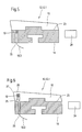
- FIGS. 2a and 3a show two schematic side views of a format slide the machine according to the invention, whereas FIGS. 2b and 3b show two perspective representations of the same.
- the format slide 16 of FIG. 2a consists of a base body 17 and three removable edge pieces 18.1, 18.2, 18.3, a temperature sensor 19.1, 19.2 being integrated in each of the edge pieces 18.1, 18.2.
- a plurality of temperature sensors 19.1, 19.2 arranged at a respective distance A from one another are provided, the distance A between the measuring points in each case being approximately 500 mm.
- the at least one connecting line 19.3 for the temperature sensors 19.1, 19.2 is shown in dashed lines.
- the base body 17 of the format slide 16 (and / or the drainage element, which of course can also be a drainage strip) consists of a GRP material.
- the ceramics 18.1, 18.2, 18.3 of the format slide 16 are designed as ceramic plates 18.1 ', 18.2', 18.3 'and have a height H in the range from 1 mm to 10 mm, preferably from 2 mm to 6 mm , on.
- the format slide 16 of FIG. 2a is made in one piece with a preferably constant height and it is provided with at least one height adjustment mechanism 20.
- the height adjustment mechanism 20 consists of at least one adjusting screw 20.1 together with the associated fixing screw 20.2.
- Figure 2b shows a perspective view of the format slide 16 of Figure 2a.
- the format slide 16 of FIG. 3a also consists of a base body 17 and three removable edge pieces 18.1, 18.2, 18.3, a temperature sensor 19 being integrated in the edge piece 18.1.
- the format slide 16 of FIG. 3a is made in several parts with a preferably constant height and it is provided with at least one height adjustment in the form of at least one intermediate plate 21.
- FIG. 3b shows a perspective view of the format slide 16 of FIG. 3a.
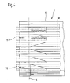
- FIG. 4 shows a second schematic plan view of a suction box 6 of the machine 1 according to the invention.
- the suction box 6 With regard to the general description of the suction box 6, reference is made to the description of the suction box 6 of FIG. 1.
- the preferably slidable format slide 16 has an extension 22 which extends in the direction of the machine center M (dashed line) and preferably touches the covering 5. Furthermore, it is permeable to a fluid, for example air or water.
- the extension 22 is - seen from above - preferably wedge-shaped and / or perforated.
- the format slide (16) also has an essentially the same surface profile as the drainage element (12) touched by the covering (5).
- each a drainage element 12 assigned drainage strips 12.1 each include a base body 14 and one connected to it by an adhesive point 23 Ceramics 18.
- the drainage strips 12.1 are each as a temperature sensor 19 a thermocouple assigned, in particular via a connecting line 19.3 be connected to a process control system 24 assigned to the machine can.
- the temperature is measured at the glue point 23.
- the temperature sensor 19 is in one In the base body 14 provided recess 25 adjacent to the glue point 23 arranged.
- the temperature is measured at the so-called "hot” ceramic zone, here inside the ceramic 18 close to the ceramic surface 26 at which the maximum temperature occurs.
- the temperature sensor 19 provided in the region of an edge 27.
- the one provided in the ceramic 15 Recess 25 was preferably in the green state, that is, before sintering the ceramic 15 generated.
- the temperature sensor 19 on one anywhere over the width of the drainage element acted upon by the covering be arranged.
- the temperature measurement value obtained is in the process control system 24 assigned to the paper machine evaluated and preferably with at least one predefinable limit compared.
- the process control system 24 is used to exceed the predefinable limit value then at least one actuator is automatically activated or influenced accordingly, to signal that the limit value has been exceeded and / or at least initiate a corresponding countermeasure with which another Counteracted heating of the monitored area of the drainage element or the monitored area is cooled.
- the Temperature measurement in particular be part of a control system that is one signal conversion following the temperature measurement and a means of of the process control system 24 includes data processing to be performed.
Landscapes
- Paper (AREA)
Applications Claiming Priority (4)
| Application Number | Priority Date | Filing Date | Title |
|---|---|---|---|
| DE10123529 | 2001-05-15 | ||
| DE2001123529 DE10123529A1 (de) | 2001-05-15 | 2001-05-15 | Verfahren und System zur Überwachung eines Entwässerungselements |
| DE10163575 | 2001-12-21 | ||
| DE2001163575 DE10163575A1 (de) | 2001-12-21 | 2001-12-21 | Maschine zur Herstellung einer Faserstoffbahn aus einer Faserstoffsuspension |
Publications (3)
| Publication Number | Publication Date |
|---|---|
| EP1260633A2 true EP1260633A2 (fr) | 2002-11-27 |
| EP1260633A3 EP1260633A3 (fr) | 2005-09-07 |
| EP1260633B1 EP1260633B1 (fr) | 2007-02-21 |
Family
ID=26009290
Family Applications (1)
| Application Number | Title | Priority Date | Filing Date |
|---|---|---|---|
| EP02010416A Expired - Lifetime EP1260633B1 (fr) | 2001-05-15 | 2002-05-08 | Machine pour la fabrication d'une bande fibreuse à partir d'une suspension fibreuse, procédé pour la surveillance d'un élément de drainage d'une machine à papier, et machine à papier avec un système de surveillance d'un élément de drainage |
Country Status (4)
| Country | Link |
|---|---|
| US (2) | US6752909B2 (fr) |
| EP (1) | EP1260633B1 (fr) |
| AT (1) | ATE354695T1 (fr) |
| DE (1) | DE50209515D1 (fr) |
Cited By (3)
| Publication number | Priority date | Publication date | Assignee | Title |
|---|---|---|---|---|
| EP1382741A3 (fr) * | 2002-07-18 | 2004-08-18 | Klaus Bartelmuss | Appareil pour la fabrication d' une bande de papier comportant au moins une bande de tamisage sans fin guidée par des rouleaux de support et de guidage |
| DE10312836A1 (de) * | 2003-03-21 | 2004-10-14 | Voith Paper Patent Gmbh | Vorrichtung zur Herstellung einer Faserstoffbahn |
| EP1845189A3 (fr) * | 2006-04-13 | 2008-04-30 | Heinz Bartelmuss | Procédé destiné à la commande de la température des éléments céramiques d'une barre d'appui ou d'une racleuse dans une installation de production de papier tout comme dispositif et barre d'appui ou racleuse destinés à l'exécution de ce procédé |
Families Citing this family (7)
| Publication number | Priority date | Publication date | Assignee | Title |
|---|---|---|---|---|
| EP1260633B1 (fr) * | 2001-05-15 | 2007-02-21 | Voith Patent GmbH | Machine pour la fabrication d'une bande fibreuse à partir d'une suspension fibreuse, procédé pour la surveillance d'un élément de drainage d'une machine à papier, et machine à papier avec un système de surveillance d'un élément de drainage |
| US7108434B2 (en) * | 2004-01-21 | 2006-09-19 | Silverbrook Research Pty Ltd | Method for printing wallpaper |
| US7186042B2 (en) | 2004-01-21 | 2007-03-06 | Silverbrook Research Pty Ltd | Wallpaper printer |
| CN102947630B (zh) * | 2010-04-30 | 2015-01-21 | 阿斯顿约翰逊公司 | 用于真空排水系统的真空控制阀门 |
| DE102018118884A1 (de) * | 2018-08-03 | 2020-02-06 | Voith Patent Gmbh | Vorrichtung zur Entwässerung einer nassgelegten Vliesstoffbahn |
| DE102018123406B3 (de) | 2018-09-24 | 2019-12-05 | Voith Patent Gmbh | Entwässerungsvorrichtung |
| FI130095B (en) * | 2019-09-09 | 2023-01-31 | Valmet Technologies Oy | Fabric for paper or cellulose technology and method for producing a fabric for paper or cellulose technology |
Family Cites Families (17)
| Publication number | Priority date | Publication date | Assignee | Title |
|---|---|---|---|---|
| DE233618C (fr) | ||||
| US4191612A (en) * | 1978-07-05 | 1980-03-04 | Ikuo Araoka | Dewatering suction apparatus for paper making machine |
| US4306934A (en) * | 1978-11-27 | 1981-12-22 | Seppanen Erkki O | Method and apparatus for forming paper |
| DE3305539C1 (de) * | 1983-02-18 | 1984-08-23 | O. Dörries GmbH, 5160 Düren | Saugkasten |
| US4718983A (en) * | 1986-07-09 | 1988-01-12 | Papyrus Inc. | Forming board structure having an adjustable leading forming board strip |
| DE3823882A1 (de) * | 1988-07-14 | 1990-01-18 | Feldmuehle Ag | Schlitzsauger |
| US5089090A (en) * | 1989-06-08 | 1992-02-18 | Jwi Ltd. | Continuous controlled drainage |
| US5538869A (en) * | 1990-12-13 | 1996-07-23 | Board Of Regents, The University Of Texas System | In-situ hybridization probes for identification and banding of specific human chromosomes and regions |
| US5976790A (en) * | 1992-03-04 | 1999-11-02 | The Regents Of The University Of California | Comparative Genomic Hybridization (CGH) |
| FI943777A7 (fi) * | 1994-08-17 | 1996-02-18 | Valmet Paper Machinery Inc | Paperikoneen vedenpoistoelin ja menetelmä sen valmistamiseksi |
| DE29615823U1 (de) * | 1996-09-13 | 1996-10-31 | Voith Sulzer Papiermaschinen GmbH, 89522 Heidenheim | Saugkasten |
| US6274002B1 (en) * | 1998-06-23 | 2001-08-14 | Wilbanks International, Inc. | Papermaking machine with variable dewatering elements including variable pulse turbulation blades adjusted by computer control system in response to sensors of paper sheet characteristics |
| US6375799B1 (en) * | 1999-01-28 | 2002-04-23 | Voith Sulzer Papiertechnik Patent Gmbh | Process and apparatus for producing a fibrous material web |
| MXPA03003453A (es) * | 2000-10-16 | 2005-06-22 | Essen Roy Van | Caja de drenaje con actividad ajustable. |
| EP1260633B1 (fr) * | 2001-05-15 | 2007-02-21 | Voith Patent GmbH | Machine pour la fabrication d'une bande fibreuse à partir d'une suspension fibreuse, procédé pour la surveillance d'un élément de drainage d'une machine à papier, et machine à papier avec un système de surveillance d'un élément de drainage |
| DE10163575A1 (de) * | 2001-12-21 | 2003-07-03 | Voith Paper Patent Gmbh | Maschine zur Herstellung einer Faserstoffbahn aus einer Faserstoffsuspension |
| DE10123529A1 (de) * | 2001-05-15 | 2002-11-21 | Voith Paper Patent Gmbh | Verfahren und System zur Überwachung eines Entwässerungselements |
-
2002
- 2002-05-08 EP EP02010416A patent/EP1260633B1/fr not_active Expired - Lifetime
- 2002-05-08 AT AT02010416T patent/ATE354695T1/de active
- 2002-05-08 DE DE50209515T patent/DE50209515D1/de not_active Expired - Lifetime
- 2002-05-14 US US10/145,855 patent/US6752909B2/en not_active Expired - Fee Related
-
2004
- 2004-01-20 US US10/761,103 patent/US6821389B2/en not_active Expired - Fee Related
Cited By (3)
| Publication number | Priority date | Publication date | Assignee | Title |
|---|---|---|---|---|
| EP1382741A3 (fr) * | 2002-07-18 | 2004-08-18 | Klaus Bartelmuss | Appareil pour la fabrication d' une bande de papier comportant au moins une bande de tamisage sans fin guidée par des rouleaux de support et de guidage |
| DE10312836A1 (de) * | 2003-03-21 | 2004-10-14 | Voith Paper Patent Gmbh | Vorrichtung zur Herstellung einer Faserstoffbahn |
| EP1845189A3 (fr) * | 2006-04-13 | 2008-04-30 | Heinz Bartelmuss | Procédé destiné à la commande de la température des éléments céramiques d'une barre d'appui ou d'une racleuse dans une installation de production de papier tout comme dispositif et barre d'appui ou racleuse destinés à l'exécution de ce procédé |
Also Published As
| Publication number | Publication date |
|---|---|
| US20020170692A1 (en) | 2002-11-21 |
| US6821389B2 (en) | 2004-11-23 |
| EP1260633A3 (fr) | 2005-09-07 |
| ATE354695T1 (de) | 2007-03-15 |
| EP1260633B1 (fr) | 2007-02-21 |
| US6752909B2 (en) | 2004-06-22 |
| DE50209515D1 (de) | 2007-04-05 |
| US20040163786A1 (en) | 2004-08-26 |
Similar Documents
| Publication | Publication Date | Title |
|---|---|---|
| EP0571585B1 (fr) | Machine a papier a deux toiles | |
| EP1314817A1 (fr) | Procédé et machine pour fabriquer une bande fibreuse | |
| EP1260633B1 (fr) | Machine pour la fabrication d'une bande fibreuse à partir d'une suspension fibreuse, procédé pour la surveillance d'un élément de drainage d'une machine à papier, et machine à papier avec un système de surveillance d'un élément de drainage | |
| DE4002304A1 (de) | Former in einer papiermaschine | |
| DE60215694T2 (de) | Verfahren und vorrichtung zur regelung der siebpartie | |
| EP2313552B1 (fr) | Procédé d'optimisation du bilan énergétique des unités de formage dans des machines de fabrication de bandes de matières fibreuses, ainsi qu'unité de formage | |
| EP0779393B1 (fr) | Calandre pour le traitement d'une bande de papier et application pour cette calandre | |
| AT392989B (de) | Stoffauflauf fuer papiermaschinen | |
| DE10163575A1 (de) | Maschine zur Herstellung einer Faserstoffbahn aus einer Faserstoffsuspension | |
| EP0831173A2 (fr) | Caisse aspirante à coulisseau de dimensionnement | |
| DE60015132T2 (de) | Verfahren zum messen und regeln von blattwellungen in einer papier- oder pappemaschine | |
| DE69915130T2 (de) | Verfahren und vorrichtung zur papierherstellung | |
| DE69217073T2 (de) | Entwasserungseinheit mit automatischer schlitzdüse | |
| DE4321061B4 (de) | Verfahren und Vorrichtung zur Beeinflussung von Dicke und Glanz und/oder Glätte bei der Behandlung von Faserstoffbahnen | |
| WO1993012291A1 (fr) | Machine a papier a deux toiles | |
| AT411536B (de) | Anlage zur erzeugung eines papierbandes mit mindestens einem über trag- bzw. führungswalzen bewegten, in sich geschlossenen siebband | |
| AT409768B (de) | Verfahren und vorrichtung zur regelung von qualitätsparametern bei papier-, tissue und zellstoffentwässerungsanlagen | |
| EP1478806A1 (fr) | Dispositif de lissage | |
| EP1881106A1 (fr) | Caisse de tête d'une machine destinée à la fabrication d'une bande de matière fibreuse | |
| DE10123529A1 (de) | Verfahren und System zur Überwachung eines Entwässerungselements | |
| DE10051649A1 (de) | Pressenanordnung | |
| EP4711521A1 (fr) | Lame d'égouttage d'une machine à papier | |
| DE10257293A1 (de) | Vorrichtung zur Herstellung einer Faserstoffbahn | |
| EP1348804B1 (fr) | Machine pour fabriquer du papier de soie comprenant une presse à patin | |
| EP2072677B1 (fr) | Partie humide à deux toiles pour une machine destinée à la fabrication d'une bande de matière fibreuse à partir d'au moins une suspension de matière fibreuse |
Legal Events
| Date | Code | Title | Description |
|---|---|---|---|
| PUAI | Public reference made under article 153(3) epc to a published international application that has entered the european phase |
Free format text: ORIGINAL CODE: 0009012 |
|
| AK | Designated contracting states |
Kind code of ref document: A2 Designated state(s): AT BE CH CY DE DK ES FI FR GB GR IE IT LI LU MC NL PT SE TR |
|
| AX | Request for extension of the european patent |
Free format text: AL;LT;LV;MK;RO;SI |
|
| PUAL | Search report despatched |
Free format text: ORIGINAL CODE: 0009013 |
|
| AK | Designated contracting states |
Kind code of ref document: A3 Designated state(s): AT BE CH CY DE DK ES FI FR GB GR IE IT LI LU MC NL PT SE TR |
|
| AX | Request for extension of the european patent |
Extension state: AL LT LV MK RO SI |
|
| RIC1 | Information provided on ipc code assigned before grant |
Ipc: 7D 21G 9/00 B Ipc: 7D 21F 1/52 B Ipc: 7D 21F 1/48 A |
|
| 17P | Request for examination filed |
Effective date: 20060307 |
|
| AKX | Designation fees paid |
Designated state(s): AT DE FI IT SE |
|
| RTI1 | Title (correction) |
Free format text: MACHINE FOR PRODUCING A FIBROUS WEB FROM A FIBRE SUSPENSION, PROCESS FOR MONITORING A DEWATERING MEMBER OF A PAPERMAKING MACHINE, AND PAPERMAKING MACHINE WITH A SYSTEM FOR MONITO |
|
| GRAP | Despatch of communication of intention to grant a patent |
Free format text: ORIGINAL CODE: EPIDOSNIGR1 |
|
| RAP1 | Party data changed (applicant data changed or rights of an application transferred) |
Owner name: VOITH PATENT GMBH |
|
| GRAS | Grant fee paid |
Free format text: ORIGINAL CODE: EPIDOSNIGR3 |
|
| GRAA | (expected) grant |
Free format text: ORIGINAL CODE: 0009210 |
|
| AK | Designated contracting states |
Kind code of ref document: B1 Designated state(s): AT DE FI IT SE |
|
| REF | Corresponds to: |
Ref document number: 50209515 Country of ref document: DE Date of ref document: 20070405 Kind code of ref document: P |
|
| REG | Reference to a national code |
Ref country code: SE Ref legal event code: TRGR |
|
| PLBE | No opposition filed within time limit |
Free format text: ORIGINAL CODE: 0009261 |
|
| STAA | Information on the status of an ep patent application or granted ep patent |
Free format text: STATUS: NO OPPOSITION FILED WITHIN TIME LIMIT |
|
| 26N | No opposition filed |
Effective date: 20071122 |
|
| PGFP | Annual fee paid to national office [announced via postgrant information from national office to epo] |
Ref country code: SE Payment date: 20110513 Year of fee payment: 10 |
|
| PGFP | Annual fee paid to national office [announced via postgrant information from national office to epo] |
Ref country code: AT Payment date: 20110512 Year of fee payment: 10 Ref country code: FI Payment date: 20110512 Year of fee payment: 10 |
|
| PGFP | Annual fee paid to national office [announced via postgrant information from national office to epo] |
Ref country code: DE Payment date: 20110520 Year of fee payment: 10 Ref country code: IT Payment date: 20110524 Year of fee payment: 10 |
|
| REG | Reference to a national code |
Ref country code: SE Ref legal event code: EUG |
|
| REG | Reference to a national code |
Ref country code: AT Ref legal event code: MM01 Ref document number: 354695 Country of ref document: AT Kind code of ref document: T Effective date: 20120508 |
|
| PG25 | Lapsed in a contracting state [announced via postgrant information from national office to epo] |
Ref country code: FI Free format text: LAPSE BECAUSE OF NON-PAYMENT OF DUE FEES Effective date: 20120508 Ref country code: AT Free format text: LAPSE BECAUSE OF NON-PAYMENT OF DUE FEES Effective date: 20120508 |
|
| PG25 | Lapsed in a contracting state [announced via postgrant information from national office to epo] |
Ref country code: IT Free format text: LAPSE BECAUSE OF NON-PAYMENT OF DUE FEES Effective date: 20120508 Ref country code: SE Free format text: LAPSE BECAUSE OF NON-PAYMENT OF DUE FEES Effective date: 20120509 |
|
| REG | Reference to a national code |
Ref country code: DE Ref legal event code: R119 Ref document number: 50209515 Country of ref document: DE Effective date: 20121201 |
|
| PG25 | Lapsed in a contracting state [announced via postgrant information from national office to epo] |
Ref country code: DE Free format text: LAPSE BECAUSE OF NON-PAYMENT OF DUE FEES Effective date: 20121201 |