EP1260656B1 - Caisson de boíte d'attente - Google Patents
Caisson de boíte d'attente Download PDFInfo
- Publication number
- EP1260656B1 EP1260656B1 EP02356095A EP02356095A EP1260656B1 EP 1260656 B1 EP1260656 B1 EP 1260656B1 EP 02356095 A EP02356095 A EP 02356095A EP 02356095 A EP02356095 A EP 02356095A EP 1260656 B1 EP1260656 B1 EP 1260656B1
- Authority
- EP
- European Patent Office
- Prior art keywords
- box
- casing
- connection box
- reinforcement connection
- edge
- Prior art date
- Legal status (The legal status is an assumption and is not a legal conclusion. Google has not performed a legal analysis and makes no representation as to the accuracy of the status listed.)
- Expired - Lifetime
Links
- 230000002787 reinforcement Effects 0.000 title claims description 23
- 239000000463 material Substances 0.000 claims abstract description 13
- 230000003014 reinforcing effect Effects 0.000 claims abstract description 6
- 239000004567 concrete Substances 0.000 claims description 17
- 238000000605 extraction Methods 0.000 claims description 11
- 238000005520 cutting process Methods 0.000 claims description 10
- 239000002184 metal Substances 0.000 claims description 7
- 239000004033 plastic Substances 0.000 abstract description 2
- 229920002994 synthetic fiber Polymers 0.000 abstract description 2
- XLYOFNOQVPJJNP-UHFFFAOYSA-N water Substances O XLYOFNOQVPJJNP-UHFFFAOYSA-N 0.000 abstract 1
- 239000000853 adhesive Substances 0.000 description 3
- 230000001070 adhesive effect Effects 0.000 description 3
- 238000005266 casting Methods 0.000 description 3
- 239000000470 constituent Substances 0.000 description 3
- 238000010276 construction Methods 0.000 description 3
- 239000011150 reinforced concrete Substances 0.000 description 3
- 125000006850 spacer group Chemical group 0.000 description 3
- 239000004743 Polypropylene Substances 0.000 description 2
- 238000009434 installation Methods 0.000 description 2
- -1 polypropylene Polymers 0.000 description 2
- 229920001155 polypropylene Polymers 0.000 description 2
- 238000007789 sealing Methods 0.000 description 2
- 239000002699 waste material Substances 0.000 description 2
- 230000001413 cellular effect Effects 0.000 description 1
- 238000000354 decomposition reaction Methods 0.000 description 1
- 230000007423 decrease Effects 0.000 description 1
- 238000001035 drying Methods 0.000 description 1
- 230000000694 effects Effects 0.000 description 1
- 238000009415 formwork Methods 0.000 description 1
- 238000000034 method Methods 0.000 description 1
- 238000011084 recovery Methods 0.000 description 1
- 239000005871 repellent Substances 0.000 description 1
- 238000003466 welding Methods 0.000 description 1
Images


Classifications
-
- E—FIXED CONSTRUCTIONS
- E04—BUILDING
- E04G—SCAFFOLDING; FORMS; SHUTTERING; BUILDING IMPLEMENTS OR AIDS, OR THEIR USE; HANDLING BUILDING MATERIALS ON THE SITE; REPAIRING, BREAKING-UP OR OTHER WORK ON EXISTING BUILDINGS
- E04G21/00—Preparing, conveying, or working-up building materials or building elements in situ; Other devices or measures for constructional work
- E04G21/12—Mounting of reinforcing inserts; Prestressing
- E04G21/125—Reinforcement continuity box
-
- E—FIXED CONSTRUCTIONS
- E04—BUILDING
- E04G—SCAFFOLDING; FORMS; SHUTTERING; BUILDING IMPLEMENTS OR AIDS, OR THEIR USE; HANDLING BUILDING MATERIALS ON THE SITE; REPAIRING, BREAKING-UP OR OTHER WORK ON EXISTING BUILDINGS
- E04G9/00—Forming or shuttering elements for general use
- E04G9/02—Forming boards or similar elements
- E04G9/021—Forming boards or similar elements the form surface being of cardboard
Definitions
- the invention relates to the field of public works and construction. More specifically, it aims at new box box structures. It is recalled that a waiting box is a support device for reinforcements link between two reinforced concrete construction elements, which contains the portions of the reinforcements whose visible part is intended to be embedded in the concrete of one of the building elements.
- the reinforcements In known manner, the reinforcements must be held in place of the casting concrete, and are usually partially contained within a device called "box of waiting", and constituted of a box which contains extremities folded frames, while leaving apparent the part of the frames that will be drowned in concrete. After pouring the concrete, we eliminate the box waiting for reveal the ends of the reinforcements that have been isolated from the concrete. The folded ends are then unfolded, and are then embedded within the adjacent element.
- box of waiting constituted of a box which contains extremities folded frames, while leaving apparent the part of the frames that will be drowned in concrete.
- This box is made from alveolar polypropylene, whose channels are parallel to the big direction of the waiting box.
- the openings of passage pierced on the back face are connected by a transverse slot, which is traversed by the central part of the frames during their installation in the box.
- This transverse slit which covers the almost the entire width of the box, is a risk of leakage. Indeed, under the effect of the concrete pressure, this transverse slot can have tend to slightly open, and let the milt of concrete.
- the objective of the present invention is therefore to overcome these different disadvantages, by proposing a box of waiting box which presents a strong rigidity while being extremely easy to extract, whose sealing properties are superior to similar solutions of the prior art.
- this extractable box is characterized in that its face rear has a fold oriented towards the inside of the box.
- This fold has an edge cutable which is located at the front face, between the shutters of the latter. After cutting, this edge is intended to facilitate the extraction of this caisson.
- the rear face of the box is configured in such a way that part of the leaf that constitutes it is present near the front face.
- the user when extracting the box, the user can split the back side of the box by cutting out the characteristic fold, which is not in contact with the concrete, but opposite the side of the front of the box, and therefore easily accessible.
- this characteristic fold constitutes a longitudinal reinforcement which is present between the front and rear faces of the box.
- the rigidity of the box is therefore increased, and therefore its resistance to the pressure exerted by the concrete during the casting.
- the characteristic fold may have recesses at its edge.
- the amount of material to be cut for the extraction operation is limited to only the areas of presence of the sheet foldable on the edge of the characteristic fold.
- these recesses may have a certain width, or else still be reduced to a simple slot.
- the fold may have lights connecting the passage openings of the same metal frame.
- these lights are notches inside the fold characteristic, in which the central parts of the frames can come accommodate, without changing the position of the fold inside the box.
- These lights made in the fold are therefore particularly advantageous for facilitating the set up the frames in the waiting box. They allow for frames to cross the back of the box without causing deformation excessive withdrawal.
- the recesses made at the edge of the folds can be connected to the lights connecting the passage openings of metal frames.
- the areas of material to be cut on the edge are located between the positions of each frame.
- the box may comprise a wire located inside the fold, at the edge of the fold, intended to facilitate the tearing of the fold during extraction of the waiting box.
- the box is equipped with a rigid wire, which can be metallic or synthetic, or which, in general, is sufficiently strong to cause the tearing of the constituent material of the box when the user exercises a sufficient traction.
- the box can have two components ends, ensuring the closure of the waiting box.
- Each end flap can be formed of several separate individual components at the level of the fold of the face back.
- each end flap consists of two flaps between them, defining between them an area which can be crossed by the rigid wire of cutting. This decomposition of the end flap into two distinct portions also facilitates the extraction of the waiting box, since the halves of the box, located on either side of the characteristic fold can be extracted independently of one another.
- the waiting box can be made from two independent half-leaves, secured, for example by an adhesive, to level of their edges opposite, so as to form the edge of the fold feature.
- the invention relates to a box of waiting box that can be made from a sheet of a foldable material such as water-repellent cardboard, plastic or foldable synthetic materials, and for example cellular polypropylene.
- a box of waiting box can be made from a sheet of a foldable material such as water-repellent cardboard, plastic or foldable synthetic materials, and for example cellular polypropylene.
- the application can for example be obtained from the cut sheet illustrated in Figure 1.
- This sheet (1) comprises different parallel areas for forming the different faces of the box.
- the sheet (1) comprises two zones (2, 3) which are intended to form the back side of the box after folding.
- Zones (2, 3) are lined outward two zones (4, 5) which will form the lateral zones of the box after folding.
- the lateral zones (4, 5) are connected to shutters (6, 7) forming each half of the front of the box.
- shutters (6, 7) are connected to flaps (8, 9) which are folded towards the inside of the box, for forming a zone serving as a spacer between the rear and front faces.
- central zone (10) consisting of two symmetrical parts (11, 12) with respect to the median axis (13).
- This central zone (10) will form after folding the characteristic fold.
- the width, measured in a transverse direction, of the parts (11, 12) of the fold is substantially equal to the width measured in the same direction of the lateral faces (4, 5).
- the edge (14) of the fold, located on the axis of symmetry (13) is found after folding and as illustrated in FIGS. 2 and 3, substantially at the level of the face front of the box.
- the edge (14) of the fold (15) is strongly perforated by the presence of recesses (16). Between two recesses consecutive section (16), the edge has a portion (17) which connects the two halves of the leaf in a transverse direction.
- the amount of material present at the level of the edge (14) is relatively small compared to the total length of the caisson.
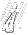
- the two halves (2, 3) of the rear face have openings (20) for allowing the passage of the reinforcements some of which are shown in Figure 2.
- These openings (20) are interconnected by slots (21) extending from the opening (20) and the entire length of the half (2, 3) of the rear face. So after folding, the slits (21) connected to the apertures (20) each occupy a little less than the half the width of the box. They therefore have a better resistance to deformation and opening that similar slits observed in caissons of the prior art which, on the contrary, extend over the quasi width of the box. The tightness of the box according to the invention is therefore significantly improved.
- these slots (21) are connected to lights which extend almost the entire width of the central zone (10) intended to form the fold (15).
- These lights (22) have a width, measured in the direction longitudinal of the box, which is slightly greater than the diameter of the reinforcement intended to be put in place in the box.
- these lights (22) forming notches intended to be traversed by the central portion (44) of a armature (45), when setting up the latter in the box. The presence of these notches avoids too much deformation of the fold (15) during the introduction frames.
- the central fold (15) When mounting the box, as shown in Figure 2, the central fold (15) has a height substantially equal to that of the box, so that form a spacer increasing the resistance of the box to crushing. This resistance to crushing is further increased by the presence of the flaps (8, 9) which also have a width substantially identical to the height of the fold (15). In this way, the central part of the box has four longitudinal elements present between the front face and the rear face, which therefore increases the rigidity of all.
- this wire may be metallic or even a sufficiently rigid wire to allow tearing the constituent material of the box.
- This thread is put in place by sliding between the two walls (11, 12) which form the fold (15).
- the introduction of this wire is made possible by the fact that the end flaps (23, 24) form two separate shutters, which each shut one half of the box.
- These flaps (23, 24) have flaps (25, 26) intended to penetrate inside the box when folding.
- additional flaps (27, 28) are provided at the ends of the lateral faces (4, 5). relative of the two halves of the box is provided by the loop (44) reinforcements.
- the waiting box When the waiting box has been equipped with frames, then set up in a formwork and that it is to extract it after drying of the concrete, it is enough for the user pulling on the wire (32) provided for this purpose so that the portions of material (17) are very quickly torn, and that the box is divided into two portions.
- the operator then only has to exert traction on a flap (6, 7) of the front panel so that the entire corresponding half-box is extracted from its housing, the metal frames sliding in their openings, or else through the slots (21), depending on the type of frames used.
- the waiting box can be constituted by the assembly of two half sheets (41) as shown in Figure 5.
- This assembly can be obtained by adhesive, stapling, welding, or any other means, at the edges (42) opposite.
- the half-plates are of different dimensions, It is possible to combine them to widen the range of waiting boxes the invention.
Landscapes
- Engineering & Computer Science (AREA)
- Architecture (AREA)
- Mechanical Engineering (AREA)
- Civil Engineering (AREA)
- Structural Engineering (AREA)
- Cartons (AREA)
- Forms Removed On Construction Sites Or Auxiliary Members Thereof (AREA)
- Connection Or Junction Boxes (AREA)
- Photovoltaic Devices (AREA)
- Magnetic Resonance Imaging Apparatus (AREA)
- Branching, Merging, And Special Transfer Between Conveyors (AREA)
- Warehouses Or Storage Devices (AREA)
Description
- une face arrière percée d'ouvertures de passage des armatures de liaison qui est destinée à venir au contact avec le béton ;
- une face avant comportant deux volets rabattus l'un en direction de l'autre ;
- deux faces latérales reliant les faces avant et arrière.
- une face arrière percée d'ouvertures de passage des armatures de liaison, destinée à venir au contact avec le béton ;
- une face avant comportant deux volets rabattus l'un en direction de l'autre ; et
- deux faces latérales reliant les faces avant et arrière.
L'application peut par exemple peut être obtenue de la feuille découpée illustrée à la figure 1. Cette feuille (1) comprend différentes zones parallèles destinées à former les différentes faces de la boíte.
- une excellente facilité d'extraction, puisque la zone à découper est localisée sur la face avant du caisson, et donc facilement accessible ;
- une excellente rigidité grâce à la présence du repli central formant entretoise entre les faces avant et arrière du caisson, ce qui augmente la résistance à l'écrasement du fait de la pression exercée par le béton ;
- une bonne étanchéité du fait de la présence de fentes de passage des armatures qui sont de taille réduite ;
- une facilité d'extraction qui conduit à la récupération de deux demi caissons qui constituent des déchets de taille relativement importante, et donc plus facile à récupérer et donc à traiter.
Claims (7)
- Caisson de boíte d'attente extractible pour la mise en place d'armatures de liaison (45) entre deux parties d'ouvrage en béton, réalisé par le pliage d'une feuille (1) d'un matériau pliable, et comprenant :caractérisé en ce que la face arrière présente un repli (15) orienté vers l'intérieur du caisson, ledit repli (15) présentant une arête pouvant être découpée (14), qui est localisée au niveau de la face avant (37), entre les volets (6, 7) de cette dernière ladite arête, après découpe, étant destinée à faciliter l'extraction dudit caisson.une face arrière percée d'ouvertures (20) de passage des armatures de liaison (45), destinée à venir au contact avec le béton ;une face avant (37) comportant deux volets (6, 7) rabattus l'un en direction de l'autre ;deux faces latérales (4, 5) reliant les faces avant (37) et arrière,
- Caisson de boíte d'attente selon la revendication 1, caractérisé en ce que le repli (15) présente des évidements (16) au niveau de son arête (14).
- Caisson de boíte d'attente selon la revendication 1, caractérisé en ce que le repli (15) présente des lumières (22) reliant les ouvertures (20) de passage d'une même armature métallique.
- Caisson de boíte d'attente selon les revendications 2 et 3, caractérisé en ce que les évidements (16) réalisés au niveau de l'arête (14) sont connectés aux lumières (22) reliant les ouvertures de passage (20) des armatures métalliques.
- Caisson de boíte d'attente selon la revendication 1, caractérisé en ce qu'il comporte un fil (32) situé à l'intérieur du repli (15), au niveau de l'arête (14) de ce dernier, destiné à faciliter le déchirement du repli (15) lors de l'extraction de la boíte d'attente.
- Caisson de boíte d'attente selon la revendication 1, caractérisé en ce qu'il comporte deux volets d'extrémités assurant la fermeture de la boíte d'attente, chaque volet d'extrémité étant formé de plusieurs volets individuels (23, 24) séparés au niveau du repli (15) de la face arrière.
- Caisson de boite d'attente selon la revendication 1, caractérisé en ce qu'il est réalisé à partir de deux demi-feuilles indépendantes (41), solidarisées au niveau de leurs bords (42) en regard pour former l'arête du repli.
Applications Claiming Priority (2)
| Application Number | Priority Date | Filing Date | Title |
|---|---|---|---|
| FR0106779A FR2825108B1 (fr) | 2001-05-23 | 2001-05-23 | Caisson de boite d'attente |
| FR0106779 | 2001-05-23 |
Publications (2)
| Publication Number | Publication Date |
|---|---|
| EP1260656A1 EP1260656A1 (fr) | 2002-11-27 |
| EP1260656B1 true EP1260656B1 (fr) | 2005-12-21 |
Family
ID=8863580
Family Applications (1)
| Application Number | Title | Priority Date | Filing Date |
|---|---|---|---|
| EP02356095A Expired - Lifetime EP1260656B1 (fr) | 2001-05-23 | 2002-05-22 | Caisson de boíte d'attente |
Country Status (4)
| Country | Link |
|---|---|
| EP (1) | EP1260656B1 (fr) |
| AT (1) | ATE313672T1 (fr) |
| DE (1) | DE60208113T2 (fr) |
| FR (1) | FR2825108B1 (fr) |
Families Citing this family (3)
| Publication number | Priority date | Publication date | Assignee | Title |
|---|---|---|---|---|
| CN103696573B (zh) * | 2013-11-29 | 2016-06-29 | 中交第二航务工程局有限公司 | 钢筋绑扎用快速定位件 |
| FR3035131A1 (fr) * | 2015-04-16 | 2016-10-21 | Coffrabat | Procede de fabrication d'un element de coffrage et element de coffrage |
| FR3073876B1 (fr) * | 2017-11-20 | 2020-10-30 | Fimurex | Caisson de mise en attente d'armatures de liaison metalliques pour la realisation de planchers en beton et ensemble pour la realisation de planchers en beton integrant un tel caisson |
Family Cites Families (3)
| Publication number | Priority date | Publication date | Assignee | Title |
|---|---|---|---|---|
| CH626676A5 (fr) * | 1979-05-01 | 1981-11-30 | Witschi H | |
| FR2694954B1 (fr) * | 1992-08-18 | 1994-11-04 | Mure Ets | Caisson pour la mise en attente d'armatures de liaison entre deux parties d'ouvrage en béton contigues et coulées l'une après l'autre. |
| FR2796095B1 (fr) | 1999-07-08 | 2001-09-07 | Cogito | Caisson de boite d'attente et boite d'attente integrant un tel caisson |
-
2001
- 2001-05-23 FR FR0106779A patent/FR2825108B1/fr not_active Expired - Fee Related
-
2002
- 2002-05-22 DE DE60208113T patent/DE60208113T2/de not_active Expired - Fee Related
- 2002-05-22 AT AT02356095T patent/ATE313672T1/de not_active IP Right Cessation
- 2002-05-22 EP EP02356095A patent/EP1260656B1/fr not_active Expired - Lifetime
Also Published As
| Publication number | Publication date |
|---|---|
| FR2825108A1 (fr) | 2002-11-29 |
| DE60208113D1 (de) | 2006-01-26 |
| ATE313672T1 (de) | 2006-01-15 |
| FR2825108B1 (fr) | 2003-11-07 |
| DE60208113T2 (de) | 2006-07-13 |
| EP1260656A1 (fr) | 2002-11-27 |
Similar Documents
| Publication | Publication Date | Title |
|---|---|---|
| EP2579758B1 (fr) | Appareil distributeur de matériaux d'essuyage prédécoupés | |
| EP0013852A1 (fr) | Porte formée de profilés en résine synthétique légèrement déformables élastiquement | |
| FR2715124A1 (fr) | Gréement pour bateau à voile. | |
| EP0479661B1 (fr) | Curseur pour sachets ou sacs munis d'une fermeture plastique à deux profils emboitables | |
| EP2353430A1 (fr) | Etui à lunettes repliable | |
| EP1260656B1 (fr) | Caisson de boíte d'attente | |
| EP1067254B1 (fr) | Caisson de boíte d'attente et boíte d'attente integrant un tel caisson | |
| FR2941983A1 (fr) | Caisson de boite d'attente et boite d'attente integrant un tel caisson. | |
| EP2204331A1 (fr) | Curseur à barreaux rigidificateurs pour l'actionnement de profilés de fermeture d'un sachet | |
| FR2891491A1 (fr) | Carton a dessin | |
| EP0508850A1 (fr) | Pince à rétreindre pour tuyaux et analogues | |
| FR2916782A3 (fr) | Caisson de boite d'attente et boite d'attente integrant un tel caisson | |
| BE1025921B1 (fr) | Caisson de mise en attente d’armatures de liaison metalliques | |
| FR2714693A1 (fr) | Châssis métallique tel que châssis aluminium, pour ouvertures, vantaux équipant de tels châssis et profil utilisé pour la réalisation de ces vantaux. | |
| FR2601332A1 (fr) | Boite pliante a couvercle homogene | |
| FR2586617A1 (fr) | Dossier de classement a hauteur et largeur reglables | |
| FR2568650A1 (fr) | Dispositif de serrage d'un element souple tel que cordon, ficelle, lacet ou analogue | |
| EP1914363B1 (fr) | Boîte d'attente pour armature en béton | |
| BE1011342A6 (fr) | Enveloppe. | |
| FR2579931A1 (en) | Binders reinforced along at least one of their edges by the folding over of material | |
| EP0309370A1 (fr) | Caisson pour volet roulant | |
| FR2717110A1 (fr) | Outil de poinçonnage pour profilé métallique. | |
| BE1011155A6 (fr) | Etui a bec verseur, du type obtenu par pliage d'une feuille decoupee, et procede de fabrication d'un tel etui. | |
| EP3144238A1 (fr) | Emballage et flan pour emballage avec dispositif d'ouverture perfectionné | |
| FR2790305A1 (fr) | Profile comportant une rainure de fixation fermee, procede pour ouvrir ladite rainure et outil pour la mise en oeuvre du procede |
Legal Events
| Date | Code | Title | Description |
|---|---|---|---|
| PUAI | Public reference made under article 153(3) epc to a published international application that has entered the european phase |
Free format text: ORIGINAL CODE: 0009012 |
|
| AK | Designated contracting states |
Kind code of ref document: A1 Designated state(s): AT BE CH CY DE DK ES FI FR GB GR IE IT LI LU MC NL PT SE TR |
|
| AX | Request for extension of the european patent |
Free format text: AL;LT;LV;MK;RO;SI |
|
| 17P | Request for examination filed |
Effective date: 20030306 |
|
| AKX | Designation fees paid |
Designated state(s): AT BE CH CY DE DK ES FI FR GB GR IE IT LI LU MC NL PT SE TR |
|
| 17Q | First examination report despatched |
Effective date: 20040323 |
|
| GRAP | Despatch of communication of intention to grant a patent |
Free format text: ORIGINAL CODE: EPIDOSNIGR1 |
|
| GRAS | Grant fee paid |
Free format text: ORIGINAL CODE: EPIDOSNIGR3 |
|
| GRAA | (expected) grant |
Free format text: ORIGINAL CODE: 0009210 |
|
| AK | Designated contracting states |
Kind code of ref document: B1 Designated state(s): AT BE CH CY DE DK ES FI FR GB GR IE IT LI LU MC NL PT SE TR |
|
| PG25 | Lapsed in a contracting state [announced via postgrant information from national office to epo] |
Ref country code: IE Free format text: LAPSE BECAUSE OF FAILURE TO SUBMIT A TRANSLATION OF THE DESCRIPTION OR TO PAY THE FEE WITHIN THE PRESCRIBED TIME-LIMIT Effective date: 20051221 Ref country code: IT Free format text: LAPSE BECAUSE OF FAILURE TO SUBMIT A TRANSLATION OF THE DESCRIPTION OR TO PAY THE FEE WITHIN THE PRESCRIBED TIME-LIMIT;WARNING: LAPSES OF ITALIAN PATENTS WITH EFFECTIVE DATE BEFORE 2007 MAY HAVE OCCURRED AT ANY TIME BEFORE 2007. THE CORRECT EFFECTIVE DATE MAY BE DIFFERENT FROM THE ONE RECORDED. Effective date: 20051221 Ref country code: NL Free format text: LAPSE BECAUSE OF FAILURE TO SUBMIT A TRANSLATION OF THE DESCRIPTION OR TO PAY THE FEE WITHIN THE PRESCRIBED TIME-LIMIT Effective date: 20051221 Ref country code: AT Free format text: LAPSE BECAUSE OF FAILURE TO SUBMIT A TRANSLATION OF THE DESCRIPTION OR TO PAY THE FEE WITHIN THE PRESCRIBED TIME-LIMIT Effective date: 20051221 Ref country code: GB Free format text: LAPSE BECAUSE OF FAILURE TO SUBMIT A TRANSLATION OF THE DESCRIPTION OR TO PAY THE FEE WITHIN THE PRESCRIBED TIME-LIMIT Effective date: 20051221 Ref country code: FI Free format text: LAPSE BECAUSE OF FAILURE TO SUBMIT A TRANSLATION OF THE DESCRIPTION OR TO PAY THE FEE WITHIN THE PRESCRIBED TIME-LIMIT Effective date: 20051221 |
|
| REG | Reference to a national code |
Ref country code: GB Ref legal event code: FG4D Free format text: NOT ENGLISH |
|
| REG | Reference to a national code |
Ref country code: CH Ref legal event code: EP |
|
| REG | Reference to a national code |
Ref country code: IE Ref legal event code: FG4D Free format text: LANGUAGE OF EP DOCUMENT: FRENCH |
|
| REF | Corresponds to: |
Ref document number: 60208113 Country of ref document: DE Date of ref document: 20060126 Kind code of ref document: P |
|
| PG25 | Lapsed in a contracting state [announced via postgrant information from national office to epo] |
Ref country code: DK Free format text: LAPSE BECAUSE OF FAILURE TO SUBMIT A TRANSLATION OF THE DESCRIPTION OR TO PAY THE FEE WITHIN THE PRESCRIBED TIME-LIMIT Effective date: 20060321 Ref country code: SE Free format text: LAPSE BECAUSE OF FAILURE TO SUBMIT A TRANSLATION OF THE DESCRIPTION OR TO PAY THE FEE WITHIN THE PRESCRIBED TIME-LIMIT Effective date: 20060321 Ref country code: GR Free format text: LAPSE BECAUSE OF FAILURE TO SUBMIT A TRANSLATION OF THE DESCRIPTION OR TO PAY THE FEE WITHIN THE PRESCRIBED TIME-LIMIT Effective date: 20060321 |
|
| PG25 | Lapsed in a contracting state [announced via postgrant information from national office to epo] |
Ref country code: ES Free format text: LAPSE BECAUSE OF FAILURE TO SUBMIT A TRANSLATION OF THE DESCRIPTION OR TO PAY THE FEE WITHIN THE PRESCRIBED TIME-LIMIT Effective date: 20060401 |
|
| PG25 | Lapsed in a contracting state [announced via postgrant information from national office to epo] |
Ref country code: PT Free format text: LAPSE BECAUSE OF FAILURE TO SUBMIT A TRANSLATION OF THE DESCRIPTION OR TO PAY THE FEE WITHIN THE PRESCRIBED TIME-LIMIT Effective date: 20060522 |
|
| PG25 | Lapsed in a contracting state [announced via postgrant information from national office to epo] |
Ref country code: MC Free format text: LAPSE BECAUSE OF NON-PAYMENT OF DUE FEES Effective date: 20060531 |
|
| NLV1 | Nl: lapsed or annulled due to failure to fulfill the requirements of art. 29p and 29m of the patents act | ||
| GBV | Gb: ep patent (uk) treated as always having been void in accordance with gb section 77(7)/1977 [no translation filed] |
Effective date: 20051221 |
|
| REG | Reference to a national code |
Ref country code: IE Ref legal event code: FD4D |
|
| PLBE | No opposition filed within time limit |
Free format text: ORIGINAL CODE: 0009261 |
|
| STAA | Information on the status of an ep patent application or granted ep patent |
Free format text: STATUS: NO OPPOSITION FILED WITHIN TIME LIMIT |
|
| 26N | No opposition filed |
Effective date: 20060922 |
|
| PG25 | Lapsed in a contracting state [announced via postgrant information from national office to epo] |
Ref country code: TR Free format text: LAPSE BECAUSE OF FAILURE TO SUBMIT A TRANSLATION OF THE DESCRIPTION OR TO PAY THE FEE WITHIN THE PRESCRIBED TIME-LIMIT Effective date: 20051221 |
|
| PG25 | Lapsed in a contracting state [announced via postgrant information from national office to epo] |
Ref country code: CY Free format text: LAPSE BECAUSE OF FAILURE TO SUBMIT A TRANSLATION OF THE DESCRIPTION OR TO PAY THE FEE WITHIN THE PRESCRIBED TIME-LIMIT Effective date: 20051221 |
|
| PGFP | Annual fee paid to national office [announced via postgrant information from national office to epo] |
Ref country code: DE Payment date: 20090512 Year of fee payment: 8 Ref country code: LU Payment date: 20090626 Year of fee payment: 8 |
|
| PGFP | Annual fee paid to national office [announced via postgrant information from national office to epo] |
Ref country code: BE Payment date: 20090609 Year of fee payment: 8 |
|
| PGFP | Annual fee paid to national office [announced via postgrant information from national office to epo] |
Ref country code: CH Payment date: 20100517 Year of fee payment: 9 |
|
| BERE | Be: lapsed |
Owner name: COGITO Effective date: 20100531 |
|
| PG25 | Lapsed in a contracting state [announced via postgrant information from national office to epo] |
Ref country code: BE Free format text: LAPSE BECAUSE OF NON-PAYMENT OF DUE FEES Effective date: 20100531 |
|
| PG25 | Lapsed in a contracting state [announced via postgrant information from national office to epo] |
Ref country code: DE Free format text: LAPSE BECAUSE OF NON-PAYMENT OF DUE FEES Effective date: 20101201 |
|
| REG | Reference to a national code |
Ref country code: CH Ref legal event code: PL |
|
| PG25 | Lapsed in a contracting state [announced via postgrant information from national office to epo] |
Ref country code: LI Free format text: LAPSE BECAUSE OF NON-PAYMENT OF DUE FEES Effective date: 20110531 Ref country code: CH Free format text: LAPSE BECAUSE OF NON-PAYMENT OF DUE FEES Effective date: 20110531 |
|
| PG25 | Lapsed in a contracting state [announced via postgrant information from national office to epo] |
Ref country code: LU Free format text: LAPSE BECAUSE OF NON-PAYMENT OF DUE FEES Effective date: 20100522 |
|
| REG | Reference to a national code |
Ref country code: FR Ref legal event code: PLFP Year of fee payment: 15 |
|
| REG | Reference to a national code |
Ref country code: FR Ref legal event code: PLFP Year of fee payment: 16 |
|
| REG | Reference to a national code |
Ref country code: FR Ref legal event code: PLFP Year of fee payment: 17 |
|
| PGFP | Annual fee paid to national office [announced via postgrant information from national office to epo] |
Ref country code: FR Payment date: 20191017 Year of fee payment: 18 |
|
| PG25 | Lapsed in a contracting state [announced via postgrant information from national office to epo] |
Ref country code: FR Free format text: LAPSE BECAUSE OF NON-PAYMENT OF DUE FEES Effective date: 20200531 |