EP1260666A2 - Antriebsvorrichtung für ein Fenster oder eine Tür - Google Patents
Antriebsvorrichtung für ein Fenster oder eine Tür Download PDFInfo
- Publication number
- EP1260666A2 EP1260666A2 EP02011253A EP02011253A EP1260666A2 EP 1260666 A2 EP1260666 A2 EP 1260666A2 EP 02011253 A EP02011253 A EP 02011253A EP 02011253 A EP02011253 A EP 02011253A EP 1260666 A2 EP1260666 A2 EP 1260666A2
- Authority
- EP
- European Patent Office
- Prior art keywords
- drive device
- window
- actuating element
- actuating
- driver
- Prior art date
- Legal status (The legal status is an assumption and is not a legal conclusion. Google has not performed a legal analysis and makes no representation as to the accuracy of the status listed.)
- Granted
Links
Images



Classifications
-
- E—FIXED CONSTRUCTIONS
- E05—LOCKS; KEYS; WINDOW OR DOOR FITTINGS; SAFES
- E05F—DEVICES FOR MOVING WINGS INTO OPEN OR CLOSED POSITION; CHECKS FOR WINGS; WING FITTINGS NOT OTHERWISE PROVIDED FOR, CONCERNED WITH THE FUNCTIONING OF THE WING
- E05F15/00—Power-operated mechanisms for wings
- E05F15/60—Power-operated mechanisms for wings using electrical actuators
- E05F15/603—Power-operated mechanisms for wings using electrical actuators using rotary electromotors
- E05F15/611—Power-operated mechanisms for wings using electrical actuators using rotary electromotors for swinging wings
- E05F15/63—Power-operated mechanisms for wings using electrical actuators using rotary electromotors for swinging wings operated by swinging arms
-
- E—FIXED CONSTRUCTIONS
- E05—LOCKS; KEYS; WINDOW OR DOOR FITTINGS; SAFES
- E05F—DEVICES FOR MOVING WINGS INTO OPEN OR CLOSED POSITION; CHECKS FOR WINGS; WING FITTINGS NOT OTHERWISE PROVIDED FOR, CONCERNED WITH THE FUNCTIONING OF THE WING
- E05F15/00—Power-operated mechanisms for wings
- E05F15/40—Safety devices, e.g. detection of obstructions or end positions
- E05F15/41—Detection by monitoring transmitted force or torque; Safety couplings with activation dependent upon torque or force, e.g. slip couplings
-
- E—FIXED CONSTRUCTIONS
- E05—LOCKS; KEYS; WINDOW OR DOOR FITTINGS; SAFES
- E05F—DEVICES FOR MOVING WINGS INTO OPEN OR CLOSED POSITION; CHECKS FOR WINGS; WING FITTINGS NOT OTHERWISE PROVIDED FOR, CONCERNED WITH THE FUNCTIONING OF THE WING
- E05F15/00—Power-operated mechanisms for wings
- E05F15/60—Power-operated mechanisms for wings using electrical actuators
- E05F15/603—Power-operated mechanisms for wings using electrical actuators using rotary electromotors
-
- E—FIXED CONSTRUCTIONS
- E05—LOCKS; KEYS; WINDOW OR DOOR FITTINGS; SAFES
- E05Y—INDEXING SCHEME ASSOCIATED WITH SUBCLASSES E05D AND E05F, RELATING TO CONSTRUCTION ELEMENTS, ELECTRIC CONTROL, POWER SUPPLY, POWER SIGNAL OR TRANSMISSION, USER INTERFACES, MOUNTING OR COUPLING, DETAILS, ACCESSORIES, AUXILIARY OPERATIONS NOT OTHERWISE PROVIDED FOR, APPLICATION THEREOF
- E05Y2201/00—Constructional elements; Accessories therefor
- E05Y2201/20—Brakes; Disengaging means; Holders; Stops; Valves; Accessories therefor
- E05Y2201/23—Actuation thereof
- E05Y2201/232—Actuation thereof by automatically acting means
- E05Y2201/236—Actuation thereof by automatically acting means using force or torque
-
- E—FIXED CONSTRUCTIONS
- E05—LOCKS; KEYS; WINDOW OR DOOR FITTINGS; SAFES
- E05Y—INDEXING SCHEME ASSOCIATED WITH SUBCLASSES E05D AND E05F, RELATING TO CONSTRUCTION ELEMENTS, ELECTRIC CONTROL, POWER SUPPLY, POWER SIGNAL OR TRANSMISSION, USER INTERFACES, MOUNTING OR COUPLING, DETAILS, ACCESSORIES, AUXILIARY OPERATIONS NOT OTHERWISE PROVIDED FOR, APPLICATION THEREOF
- E05Y2201/00—Constructional elements; Accessories therefor
- E05Y2201/40—Motors; Magnets; Springs; Weights; Accessories therefor
- E05Y2201/43—Motors
- E05Y2201/434—Electromotors; Details thereof
-
- E—FIXED CONSTRUCTIONS
- E05—LOCKS; KEYS; WINDOW OR DOOR FITTINGS; SAFES
- E05Y—INDEXING SCHEME ASSOCIATED WITH SUBCLASSES E05D AND E05F, RELATING TO CONSTRUCTION ELEMENTS, ELECTRIC CONTROL, POWER SUPPLY, POWER SIGNAL OR TRANSMISSION, USER INTERFACES, MOUNTING OR COUPLING, DETAILS, ACCESSORIES, AUXILIARY OPERATIONS NOT OTHERWISE PROVIDED FOR, APPLICATION THEREOF
- E05Y2400/00—Electronic control; Electrical power; Power supply; Power or signal transmission; User interfaces
- E05Y2400/10—Electronic control
- E05Y2400/30—Electronic control of motors
- E05Y2400/3013—Electronic control of motors during manual wing operation
-
- E—FIXED CONSTRUCTIONS
- E05—LOCKS; KEYS; WINDOW OR DOOR FITTINGS; SAFES
- E05Y—INDEXING SCHEME ASSOCIATED WITH SUBCLASSES E05D AND E05F, RELATING TO CONSTRUCTION ELEMENTS, ELECTRIC CONTROL, POWER SUPPLY, POWER SIGNAL OR TRANSMISSION, USER INTERFACES, MOUNTING OR COUPLING, DETAILS, ACCESSORIES, AUXILIARY OPERATIONS NOT OTHERWISE PROVIDED FOR, APPLICATION THEREOF
- E05Y2600/00—Mounting or coupling arrangements for elements provided for in this subclass
- E05Y2600/40—Mounting location; Visibility of the elements
- E05Y2600/46—Mounting location; Visibility of the elements in or on the wing
-
- E—FIXED CONSTRUCTIONS
- E05—LOCKS; KEYS; WINDOW OR DOOR FITTINGS; SAFES
- E05Y—INDEXING SCHEME ASSOCIATED WITH SUBCLASSES E05D AND E05F, RELATING TO CONSTRUCTION ELEMENTS, ELECTRIC CONTROL, POWER SUPPLY, POWER SIGNAL OR TRANSMISSION, USER INTERFACES, MOUNTING OR COUPLING, DETAILS, ACCESSORIES, AUXILIARY OPERATIONS NOT OTHERWISE PROVIDED FOR, APPLICATION THEREOF
- E05Y2800/00—Details, accessories and auxiliary operations not otherwise provided for
- E05Y2800/25—Emergency conditions
-
- E—FIXED CONSTRUCTIONS
- E05—LOCKS; KEYS; WINDOW OR DOOR FITTINGS; SAFES
- E05Y—INDEXING SCHEME ASSOCIATED WITH SUBCLASSES E05D AND E05F, RELATING TO CONSTRUCTION ELEMENTS, ELECTRIC CONTROL, POWER SUPPLY, POWER SIGNAL OR TRANSMISSION, USER INTERFACES, MOUNTING OR COUPLING, DETAILS, ACCESSORIES, AUXILIARY OPERATIONS NOT OTHERWISE PROVIDED FOR, APPLICATION THEREOF
- E05Y2900/00—Application of doors, windows, wings or fittings thereof
- E05Y2900/10—Application of doors, windows, wings or fittings thereof for buildings or parts thereof
- E05Y2900/13—Type of wing
- E05Y2900/132—Doors
-
- E—FIXED CONSTRUCTIONS
- E05—LOCKS; KEYS; WINDOW OR DOOR FITTINGS; SAFES
- E05Y—INDEXING SCHEME ASSOCIATED WITH SUBCLASSES E05D AND E05F, RELATING TO CONSTRUCTION ELEMENTS, ELECTRIC CONTROL, POWER SUPPLY, POWER SIGNAL OR TRANSMISSION, USER INTERFACES, MOUNTING OR COUPLING, DETAILS, ACCESSORIES, AUXILIARY OPERATIONS NOT OTHERWISE PROVIDED FOR, APPLICATION THEREOF
- E05Y2900/00—Application of doors, windows, wings or fittings thereof
- E05Y2900/10—Application of doors, windows, wings or fittings thereof for buildings or parts thereof
- E05Y2900/13—Type of wing
- E05Y2900/148—Windows
Definitions
- the invention relates to a drive device for a window or a door, which a frame and a swing frame, which has an actuator of the window is movable, the drive device having an actuating element has by the actuating movement of the swing frame is tiltable relative to the frame, the actuating element of a Drive device of the drive device is driven, wherein the drive device has an adjusting element, by means of its adjusting movement a drive-functional coupling between the actuator and drive device the drive device is producible and detachable.
- Such a drive device for a window is known from DE 199 24 175.
- the drive device is here on the swivel frame of the window put on and is therefore visible. But it is made both from optical as well architectural reasons desired to design a drive device such that it is hardly or not at all visible, d. that is, they have a compact structure having.
- the adjusting element can be actuated and displaced in the drive device by the actuating element of the window is arranged that the actuating element with the adjusting element is rotatably connected, so that the adjusting element and thus that with it connected actuating element by a corresponding manual or motor Actuating movement of the actuator of the window at least from a first position for the tilting position of the actuating member of the window is correlated to a second position, which corresponds to the closed position of the actuating member of the window is correlated, that is movable in this first position of the adjusting element, the actuating element is in active engagement with the drive device the drive device is by a drive end of the actuator attacks on a driver of the drive device, and that between the actuator and a motor of the drive device Drive device a coupling element acting as an overload clutch is arranged.
- the measures according to the invention have the advantage that a Drive device is created, which is characterized by its compact structure. It is in an advantageous manner z. B. in a standardized Gap can be integrated between the swivel frame and the window frame, whereby it is essentially no longer visible.
- Another advantage of the drive device according to the invention is that it allows the operator, one with the drive device according to the invention equipped window or door in the usual way by the actuator to operate, in particular manually at any time by swiveling fully open. This will result in wide acceptance of such a window guaranteed.
- Another advantage of the drive device according to the invention is its high operational reliability, since it is the overload clutch provided according to the invention allowed in a simple manner, the one in the tipping mode To be able to close the window manually at any time so that it can then be closed to be able to open the swing frame in a known manner.
- Another advantage of the drive device according to the invention is that the use of an overload clutch in an advantageous manner Pinch protection for the operator.
- the appropriate setting of the maximum torque that can be transmitted by the overload clutch can be achieved in an advantageous manner that the tilting movement, in particular when closing, is interrupted when there is a risk that a body part between the swing frame and frame of the with the invention Drive device equipped window or door located.
- An advantageous development of the invention provides that the overload clutch an overload clutch with directional maximum torque is.
- Such a measure has the advantage that when opening and when closing the equipped with the drive device according to the invention Window or such a door different coupling forces can be specified through which it can be achieved that the unlocked, not in Windows in its closed position unintentionally due to a wind load is tilted.
- Another advantageous development of the invention provides that the maximum Torque that can be transmitted from the overload clutch by means of an adjusting element is adjustable. Such a measure has the advantage that it makes it easier How a window type-specific setting of the drive device is possible in a particularly simple manner.
- Another advantageous development of the invention provides that the actuating element the drive device according to the invention in a on the frame attached anchor shoe engages from which it is in its unlocked Closed position can be moved out.
- Such a measure has the advantage that this allows an unimpeded manual opening of the the drive device according to the invention equipped window or such door by pivoting with an automatically decoupling actuator is achievable.
- Another advantageous development of the invention provides that in advantageous Way the adjusting element of the drive device by its drive device driven in the drive device is displaceable.
- a Such a measure has the advantage that, on the one hand, this results in a displacement movement of the actuating element connected to the adjusting element can be achieved is, in such a way that by the corresponding displacement movement of the adjusting element in the drive device, the actuating element from its position in which its drive end is in active engagement with the driver the drive device is at least in a position in which it Active intervention is canceled, is moved, it being preferred that the sliding movement of the adjusting element is carried out so far that the actuator is in a position from which it is from the window fitting can be moved out.
- the drive device has a rack connected to the adjusting element, the meshes with a toothed segment driven by the drive device.
- a such measure has the advantage that it makes it simple the aforementioned displacement movement of the adjusting element are generated can.
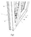
- a window F is now shown schematically, which has a frame B and a swivel frame which is arranged to be movable relative to the frame B. S owns.
- the swing frame S is in and known per se and Way of an actuator of the window F not shown in the figure operable, in such a way that by a corresponding movement of the actuator the window F can be tilted into a tilted position of the swivel frame S, by positioning the actuator of the window F in one Swivel position of the swivel frame S swiveling and by a corresponding Movement of the actuator of the window F to a closed position a locking of the swing frame S in the frame B of the window F is effected.
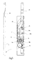
- the drive device 1 is now shown in more detail in FIGS. 2-5 and structured in principle in a drive device 10, the drive device 10 drivable actuator 20 and one of the actuator of the window F actuable adjusting element 30.
- This adjusting element 30 serves - as described further below - for the functional intervention of the actuating element 20 with the drive device 10 and solve.
- the drive device 10 has a known and therefore not Electric motor 11 described in more detail, which has a power supply and has motor electronics (not shown in each case).
- a shaft 12 of the electric motor 11 is rotatably connected to a worm shaft 13, which in turn with a drive gear 14 meshes.
- the drive gear 14 is in operative engagement with another gear 15 of a coupling element 16, which with a driver 19 cooperates, the one drive end 21 of the actuating element 20th applied.
- the actuating element 20 can be rotated via a pin 22 on the adjusting element, which is displaceably guided in the housing 2 of the drive device 1 30 stored by the pin 22 of the actuator 20 in a Receiving opening 31 of the adjusting element 30 is received.
- the adjustment movement of the adjustment element 30 in the housing 2 of the drive device 1 is now by a corresponding actuation movement of the actuator of the swing frame S of the window F causes, the actuator of the window F via a known per se and therefore not Mechanics shown in this way with the adjusting element 30 of the drive device 1 is connected that the adjusting element 30 in its shown in Figure 2 upper first position when the actuator is in an actuating position is in which the swing frame S in the window frame B of the window F is locked so that the adjusting element 30 is shown in its position shown in FIG.
- window F can be tilted by this drive device 1, so the operating element of the window F is actuated by the operator, in such a way that that the actuator is moved to its tilt position.
- the coupling of the Actuator of the window F with the above-mentioned mechanics the adjusting element 30 causes the adjusting element 30 by the actuating movement the actuator of the window F towards its lower, position shown in Figure 3 is moved. As can be seen from FIG.
- a pin 19 'of the driver 19 of the drive device 10 dips into one Receiving opening 21 'of the fork-like drive end 21 of the actuating element 20 a, so that a drive-functional intervention between the Drive device 10 and the actuating element 20 of the drive device 1 is made.
- a release switch 35 serves the drive device 10 of the drive device 1 to activate by the acted upon Release switch 35 generated signal via a in the figures Signal line, not shown, passed to the motor electronics of the electric motor 11 is activated, whereby the drive device 10, i. H. from their hibernation in her working state is transferred.
- the actuating element 20 mounted on the adjusting element 30 is made its position shown in Figure 2 in its end position shown in Figure 3 Tilting process moves, which in turn causes - as already mentioned above - one drive-functional coupling of drive device 10 with the actuating element 20 and an exposure of the release switch 35 is carried out , but that a first limit switch 36a is also applied.
- On Switching signal of the first limit switch 36a is in turn via a not shown Signal line passed to the motor electronics of the electric motor 11 and causes the drive device 10 is now switched on.
- a rotary movement of the Drive shaft 12 of the electric motor 11 is on the worm shaft 13 on the Drive gear 14 and from this via the further gear 15 and the coupling element 16 transferred to the driver 19, which causes the Driver 19 from its end position shown in Figure 3, in which the swing frame S of the window F is closed, in its end position shown in FIG. 4 moved, in which the swivel frame S is tilted. Actuated in this end position the actuating element 20 then a second limit switch 36b.
- the actuator of window F is operated to close window F lock (adjusting element 30 in its upper position) or around the swivel frame To pivot S (adjusting element 30 in its middle position) this has the consequence that by the actuating movement of the actuator and the movement of the adjusting element 30 caused thereby, the actuating element 20 is moved away from the release switch 35. This causes the drive device 10 of the drive device 1 deactivated, i. H. in their idle state is transferred.
- the actuating element of the window F is now moved into its swivel position, so this also causes - as already mentioned above - the adjusting element 30 is moved into its central position shown in FIG. 5, in which - as it can be seen from this figure - the active engagement of the drive device 10 with the actuating element 20 is canceled.
- the drive device is also 10 switched off because - as already mentioned - the actuating element 20 does not act on the release switch 35, so that the drive device 10 is deactivated.
- the swing frame S is in its closed position.
- the frame B has a recess that allows the actuator 20 can be pulled out of the frame B, which is advantageous Way a pivoting of the window F is possible.
- the tilting movement by pulling or pushing the operator on Actuator is triggered.
- the drive device 10 activated via a remote control or controlled by appropriate sensors or deactivate.
- Such an approach allows the drive device 1 to control the window F remotely by z. B. when leaving of the house, e.g. B. by locking the door lock, the window F is closed automatically.
- the drive device 1 can appropriate sensors for rain, sound, etc. can be controlled, or it is also possible in connection with a corresponding regulation that with the described Drive device 1 equipped window or door as needed to adapt to the air quality and / or room temperature and / or air humidity, by placing it in the required intermediate or end positions brought.
- limit switches 36a, 36b are used be to the drive device 10 when it reaches its first or switch off second position. But it is also possible in the drive device 10 electric torque-limited motors to use, which are then automatic turn off when necessary for the movement of the actuator 20 Torque exceeds a predefined value.
- the coupling element 16 is now advantageously as an overload clutch educated.
- the use of one as an overload clutch, in particular designed as a slip clutch, coupling element 16 has the one hand Advantage that the swivel frame S of the window F can also be tilted can, if the drive device 10 of the drive device 1 - z. B. by Power failure or blocked by self-locking or by a defect is.
- the window F is the coupling element designed as an overload clutch 16 allowed in an advantageous manner, at any time the usually motor interrupt driven tilting operation and the window F manually to close, i.e. to move it into its closed position, in which the Swing frame S - as described above - can be pivoted, whereby window F is opened.
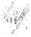
- the coupling element 16 preferably as best shown in FIG. 6.
- the driver 19 on its side facing the further gear 15 a series of grooves 18 and the other gear 15 has one of the number the grooves 18 of the driver 19 corresponding number of openings 15 ', wherein in the openings 15 'balls 17 are received by the force of a the further gear 15 acting pressure spring 16a in the grooves 18 of the Driver 19 are pressed.
- the slope of the flanks of the grooves 18 in Coordination with the contact pressure of the pressure spring 16a formed such that at a torque occurring during normal operation of the drive device 1 the balls 17 can not be moved from the grooves 18, so that the driver 19 follows the rotational movement of the further gear wheel 15.
- the coupling element 16 as a asymmetrically acting coupling element 16 is formed, d. that is, in different Direction of action the overload forces and thus the coupling forces are different levels.
- the Overload in the opening direction required to trigger the coupling element 16 is greater than the overload force in the opposite direction, for example to avoid wind pressure in its closed position located but not locked window F is opened unintentionally.
- the use of a coupling element designed as an overload clutch 16 also has the advantage that a simple way Pinch protection for the operator can be realized by the maximum by the coupling element 16 transmissible torques are selected such that the coupling element 16 the driver 19 and thus the actuating element 20 decoupled from the electric motor 11 when the actuating element continues to move 20 forces above a certain limit counteract.
- This pinch protection can be increased by the fact that the described Drive device 1 has a corresponding motor electronics, which the motor stops immediately if the motor current or its gradient is due to a in the tilt path of the swing frame S obstacle, for. B. one hand, or in the case of a gust of wind, rises above the specified limit. After an adjustable delay, the motor electronics will replace it again Attempt started within milliseconds in which the Windows because of its relatively long running time, which can be in the minute range, has not moved noticeably, can be stopped immediately.
- the danger that the operator is trapped painfully, is at best only in outermost, very low area of the window and only at particularly difficult windows. In this area this can be dangerous of pinching by appropriate, connected to the frame B, Remedial covers can also be easily remedied optically.
- the driving force of the pressure spring 16a is adjustable by an adjusting element 16b.
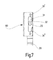
- FIG. 7 shows an anchoring shoe 60, as mentioned at the beginning, which is firmly connected to the frame B.
- the anchoring shoe 60 has an elongated hole 31 in that a driver 25 of the actuating element 20 is slidably mounted.
- is the swivel frame S is closed and locked via the actuator, is the driver 25 of the actuator 20 in its upper Position at the upper end 31 'of the slot 31.
- In the tilt position of the Swing frame S is the driver 25 at the lower end 31 "of Slot 31.
- the window is now closed and not locked, it is located the driver under the actuator 20 in front of an opening 32 of the Elongated hole 31 of the anchoring shoe 60, so that when pivoting of the swivel frame S he easily exit from the anchoring shoe 60 and when the window is subsequently closed by a pivoting movement enter the slot 31 of the anchoring shoe 60 again via the opening 32 can.
- the anchoring shoe 60 thus advantageously and An automatic coupling or uncoupling of the actuating element 20 synchronously to operate the mechanics of the actuator of the window F, and without the user having to do anything.
- the drive device 1 has a further motor (not shown), through which the actuator of the window F can be actuated, so that in an advantageous manner Way also a motorized locking of the window is made possible.
- the window F or equipped with the drive device 1 described the door is characterized in that there is a separation between that for the tilting movement of the swing frame S required force, which is taken into account the gravity of the swing frame S against the frictional forces of the Mechanics acts, and that for locking and tightly pressing not shown Seals of the window frame F required force.
- the former Force is provided by the drive device 1, which is why can be optimized for this task in an advantageous manner, while the required closing force for tightly closing the window F via the further motor, that is to say independently of the drive device 1, so that the other motor can be optimized for this task.
- FIG 8 is now a second embodiment of a drive device 1 for a window F shown, which is largely the same or similar to the first embodiment of Figures 1 to 6 is formed so that the same or corresponding parts no longer described in detail and with the same reference numerals.
- FIG. 8 has a device 50, through which the adjusting element 30 and thus the rotatable with this connected actuator 20 linearly displaced with the drive device 1 can be.
- This device 50 consists essentially of a the adjusting element 30 connected rack 51, which is linearly displaceable in the Housing 2 of the drive device 1 is guided, and which with a toothed segment 52 combs.
- the toothed segment 52 is also used here as an overload clutch acting coupling element 16 connected.
- this device 50 is now as follows: After the window F by a corresponding operation of the drive device 1 in its closed position 3 is moved, in which - as shown in Figure 3 - the Driver 19 in operative engagement with the drive end 21 of the actuating element 20 is located and the displacement element carrying the actuating element 20 30 is in its lower position, is now to the active intervention to solve between drive device 10 and actuator 20, the second Embodiment not - as in the first embodiment - the electric motor 11 of the drive device 10 is switched off by the first limit switch 36a, but the electric motor 11 continues to run. Now around the driver pin 19 'of the driver 19 from the fork-like drive end 21 of the To be able to move actuating element 20, it is provided that - like 8 is readily apparent from FIG.
- the window is designed as an overload clutch Coupling element 16 allows in an advantageous manner, at any time in the Usually motor-driven turn-tilt operation and interrupt the window F to move manually, especially then the swivel frame S-like described above - can be pivoted, whereby the window F opens becomes.
- An unwanted opening of the window during motor passage the position can be pivoted by a known in the hardware technology and standard self-latching device can be prevented.
- An additional Secure locking can be achieved by a purely mechanical, not shown, detachable via the actuating member, or by a corresponding electromechanical, also correspondingly releasable locking device.
- window should be interpreted broadly, so that not only the normal wall window, but also e.g. B. door-like windows, such as. B. occur in balcony doors, should be included. It is not absolutely necessary that the windows also have glass elements.
- the term “window” should also be understood to mean a construction that does not have a glass pane.
- the drive device 1 is also suitable for use with actual doors.
Landscapes
- Power-Operated Mechanisms For Wings (AREA)
Abstract
Description
- Figur 1
- ein Fenster zusammen mit einem Ausführungsbeispiel einer Antriebsvorrichtung,
- Figur 2
- das Ausführungsbeispiel der Figur 1 in einer Draufsicht und einer Seitenansicht in einer einer Geschlossen-Stellung des Fensters korrespondierenden Position,
- Figur 3
- ein Ausführungsbeispiel der Antriebsvorrichtung in einer Draufsicht und in einer Seitenansicht in einer einer ersten Endposition einer Kipp-Stellung des Fensters korrespondierenden Position,
- Figur 4
- ein Ausführungsbeispiel der Antriebsvorrichtung in einer Draufsicht und in einer Seitenansicht in einer zweiten Endposition des Kipp-Vorgangs,
- Figur 5
- das Ausführungsbeispiel der Figur 1 in einer Draufsicht und einer Seitenansicht in einer einer Schwenk-Stellung des Fensters korrespondierenden Position,
- Figur 6
- eine Explosionsdarstellung des Ausführungsbeispiel,
- Figur 7
- ein Ausführungsbeispiel eines das Betätigungselement am Blendrahmen haltenden Verankerungsschuhs, und
- Figur 8
- eine Explosionsdarstellung eines zweiten Ausführungsbeispiels.
Es soll unter dem Begriff "Fenster" auch eine keine Glasscheibe aufweisende Konstruktion verstanden werden. Selbstverständlich ist die Antriebsvorrichtung 1 auch zum Einsatz bei eigentlichen Türen geeignet.
Claims (20)
- Antriebsvorrichtung für ein Fenster (F) oder eine Tür, welches einen Blendrahmen (B) und einen Schwenkrahmen (S), der über ein Betätigungsorgan des Fensters (F) bewegbar ist, besitzt, wobei die Antriebsvorrichtung (1) ein Betätigungselement (20) aufweist, durch dessen Betätigungsbewegung der Schwenkrahmen (S) relativ zum Blendrahmen (B) kippbar ist, wobei das Betätigungselement (20) von einer Antriebseinrichtung (10) der Antriebsvorrichtung (1) angetrieben ist, wobei die Antriebsvorrichtung (1) ein Verstellelement (30) aufweist, durch dessen Verstellbewegung eine antriebsfunktionelle Kopplung zwischen Betätigungselement (20) und Antriebseinrichtung (10) der Antriebsvorrichtung (1) herstellbar und lösbar ist, dadurch gekennzeichnet, daß das Verstellelement (30) vom Betätigungsorgan des Fensters (F) betätigbar und verschiebbar in der Antriebsvorrichtung (1) angeordnet ist, daß mit dem Verstellelement (30) das Betätigungselement (20) drehbeweglich verbunden ist, so daß das Verstellelement (30) und somit das mit ihm verbundene Betätigungselement (20) durch eine entsprechende manuelle oder motorische Betätigungsbewegung des Betätigungsorgans des Fensters (F) zumindest von einer ersten Position, die zur Kipp-Stellung des Betätigungsorgans des Fensters korreliert ist, in eine zweite Position, die zur Geschlossen-Stellung des Betätigungsorgans des Fensters (F) korreliert ist, bewegbar ist, daß in dieser ersten Position des Verstellelements (30) das Betätigungselement (20) in Wirkeingriff mit der Antriebseinrichtung (10) der Antriebsvorrichtung (1) ist, indem ein Antriebsende (21) des Betätigungselements (20) an einem Mitnehmer (19) der Antriebseinrichtung (10) angreift, und daß zwischen dem Betätigungselement (20) und einem Motor (11) der Antriebseinrichtung (10) der Antriebsvorrichtung (1) ein als Überlastkupplung fungierendes Kupplungselement (16) angeordnet ist.
- Antriebsvorrichtung nach Anspruch 1, dadurch gekennzeichnet, daß das Kupplungselement (16) als ein asymmetrisches Kupplungselement ausgebildet ist, dessen Überlastkraft in einer Richtung größer ist als in der dieser Richtung entgegengesetzten anderen Richtung.
- Antriebsvorrichtung nach Anspruch 2, dadurch gekennzeichnet, daß die Überlast des Kupplungselements (16) in Kipp-Richtung größer als in SchließRichtung ist.
- Antriebsvorrichtung nach einem der vorangehenden Ansprüche, dadurch gekennzeichnet, daß das Kupplungselement (16) zwischen dem das Betätigungselement (20) beaufschlagenden Mitnehmer (19) und dem Motor (11) der Antriebseinrichtung (10) angeordnet ist.
- Antriebsvorrichtung nach Anspruch 4, dadurch gekennzeichnet, daß der Mitnehmer (19) an seiner einem vom Antriebszahnrad (14) angetriebenen weiteren Zahnrad (15) zugewandten Seite eine Anzahl von Nuten (18) aufweist, und daß das weitere Zahnrad (15) eine der Anzahl der Nuten (18) des Mitnehmers (19) entsprechende Anzahl von Öffnungen (15') aufweist, wobei in den Öffnungen (15') Kugeln (17) aufgenommen sind, die durch die Kraft einer das weitere Zahnrad (15) beaufschlagenden Andruckfeder (16a) in die Nuten (18) des Mitnehmers (19) gedrückt sind.
- Antriebsvorrichtung nach Anspruch 5, dadurch gekennzeichnet, daß mindestens eine der Nuten (18) Flanken (18', 18") aufweist, und daß die Steilheit einer Flanke (18") größer ist als die Steilheit der anderen Flanke (18') der Nut (18).
- Antriebsvorrichtung nach einem der vorangehenden Ansprüche, dadurch gekennzeichnet, daß das Verstellelement (30) in der zweiten Position einen Freigabeschalter (35) beaufschlagt, dessen zur Antriebseinrichtung (10) geleitetes Signal eine Aktivierung der Antriebseinrichtung (10) der Antriebsvorrichtung (1) bewirkt, daß die Antriebsvorrichtung (1) zwei von dem Betätigungselement (20) beaufschlagbare Endschalter (36a, 36b) aufweist, wobei in einer ersten Endposition des in antriebsfunktionellem Wirkeingriff mit der Antriebseinrichtung (10) befindlichen Betätigungselements (20) dieses den ersten Endschalter (36a) und in einer zweiten Endposition den zweiten Endschalter (36b) beaufschlagt, so daß bei einer von der ersten zur zweiten Endposition verlaufenden Bewegung des Betätigungselements (20) beim Erreichen der zweiten Endposition infolge der dann bewirkten Beaufschlagung des zweiten Endschalters (36b) die Antriebseinrichtung (10) abschaltbar ist, und daß durch eine manuell initiierte Auslenkung des Betätigungselements (20) aus seiner zweiten Endposition infolge der dann aufgehobenen Beaufschlagung des zweiten Endschalters (36b) die Antriebseinrichtung(10) einschaltbar ist, und daß eine Bewegung des Betätigungselements (20) von der zweiten Endposition in seine erste Endposition bewirkt, daß beim Erreichen der ersten Endposition des Betätigungselements (20) der erste Endschalter (36a) zur Abschaltung der Antriebseinrichtung (10) durch das Betätigungselement (20) beaufschlagbar ist.
- Antriebsvorrichtung nach Anspruch 7, dadurch gekennzeichnet, daß durch eine Auslenkung des Verstellelements (30) aus seiner zweiten Position die Beaufschlagung des Freigabeschalters (35) zwecks Deaktivierung der Antriebseinrichtung (10) aufhebbar ist.
- Antriebsvorrichtung nach einem der vorangehenden Ansprüche, dadurch gekennzeichnet, daß das Verstellelement (30) in eine zur Schwenk-Stellung des Betätigungsorgans des Fensters (F) korrelierte dritten Position verschiebbar ist, in der der Wirkeingriff zwischen Betätigungselement (20) und Antriebseinrichtung (10) aufgehoben und das Betätigungselement (20) aus dem Blendrahmen (B) des Fensters (F) herausbewegbar ist.
- Antriebsvorrichtung nach einem der vorangehenden Ansprüche, dadurch gekennzeichnet, daß das Betätigungselement (20) mit dem Verstellelement (30) drehbeweglich verbunden ist.
- Antriebsvorrichtung nach Anspruch 10, dadurch gekennzeichnet, daß ein Zapfen (22) des Betätigungselements (20) in einer Aufnahmeöffnung (32) des Verstellelements (30) aufgenommen ist.
- Antriebsvorrichtung nach einem der vorangehenden Ansprüche, dadurch gekennzeichnet, daß der Mitnehmer (19) einen Mitnehmerzapfen (19') aufweist, der in eine Aufnahmeöffnung (21') des gabelartig ausgeführten Antriebsendes (21) des Betätigungselements (20) eintretbar ist.
- Antriebsvorrichtung nach Anspruch 12, dadurch gekennzeichnet, daß das gabelartig ausgeführte Antriebsende (21) des Betätigungselements (20) einen Endfortsatz (21a) aufweist, der eine derartige Länge besitzt, daß ein seitliches Herausbewegen des Mitnehmerzapfens (19') des Mitnehmers (19) aus dem gabelartig ausgeführten Antriebsende (21) des Betätigungselements (20) durchführbar ist.
- Antriebsvorrichtung nach einem der vorangehenden Ansprüche, dadurch gekennzeichnet, daß die Antriebsvorrichtung (1) eine Einrichtung (50) aufweist, durch die eine motorisch angetriebene Verschiebebewegung des Verstellelements (30) in der Antriebsvorrichtung (1) durchführbar ist.
- Antriebsvorrichtung nach einem der vorangehenden Ansprüche, dadurch gekennzeichnet, daß die Einrichtung (50) eine Zahnstange (51), welche mit dem Verstellelement (30) verbunden ist, sowie ein mit der Zahnstange (51) kämmendes Zahnsegment (52) aufweist.
- Antriebsvorrichtung nach einem der vorangehenden Ansprüche, dadurch gekennzeichnet, daß die Antriebseinrichtung (10) einen Motor (11) mit einer Motorelektronik aufweist, und daß die Signale des Freigabeschalters (35) und der Endschalter (36a, 36b) der Motorelektronik zugeführt sind.
- Antriebsvorrichtung nach einem der vorangehenden Ansprüche, dadurch gekennzeichnet, daß die Antriebsvorrichtung einen weiteren Motor aufweist, durch den das Betätigungsorgan des Fensters (F) betätigbar ist.
- Fenster oder Tür, gekennzeichnet durch eine Antriebsvorrichtung (1) der Ansprüche 1-17.
- Fenster oder Tür nach Anspruch 18, dadurch gekennzeichnet, daß am Blendrahmen (B) ein Verankerungsschuh (60) angeordnet ist, in dem das Betätigungselement (20) eingreifbar ist.
- Fenster oder Tür nach Anspruch 19, dadurch gekennzeichnet, daß der Verankerungsschuh (60) ein Langloch (31) aufweist, in dem ein Mitnehmer (25) des Betätigungselements (20) verschiebbar gelagert ist, und daß das Langloch (31) eine Öffnung (32) aufweist, durch die der Mitnehmer (25) des Betätigungselements (20) in der nicht-verriegelten Geschlossen-Stellung des Schwenkrahmens (S) aus dem Verankerungsschuh (60) durch eine Schwenkbewegung des Schwenkrahmens (S) hinein- und herausbewegbar ist.
Applications Claiming Priority (4)
| Application Number | Priority Date | Filing Date | Title |
|---|---|---|---|
| DE10125518 | 2001-05-23 | ||
| DE10125518A DE10125518B4 (de) | 2001-05-23 | 2001-05-23 | Antriebsvorrichtung für ein Fenster oder eine Tür |
| DE10143372 | 2001-09-04 | ||
| DE10143372A DE10143372C1 (de) | 2001-09-04 | 2001-09-04 | Einrichtung zur Verriegelung für ein Drehkippfenster oder eine Tür |
Publications (3)
| Publication Number | Publication Date |
|---|---|
| EP1260666A2 true EP1260666A2 (de) | 2002-11-27 |
| EP1260666A3 EP1260666A3 (de) | 2004-11-10 |
| EP1260666B1 EP1260666B1 (de) | 2008-11-26 |
Family
ID=26009393
Family Applications (1)
| Application Number | Title | Priority Date | Filing Date |
|---|---|---|---|
| EP02011253A Expired - Lifetime EP1260666B1 (de) | 2001-05-23 | 2002-05-22 | Antriebsvorrichtung für ein Fenster oder eine Tür |
Country Status (3)
| Country | Link |
|---|---|
| EP (1) | EP1260666B1 (de) |
| AT (1) | ATE415538T1 (de) |
| DE (1) | DE50213039D1 (de) |
Cited By (2)
| Publication number | Priority date | Publication date | Assignee | Title |
|---|---|---|---|---|
| EP1449994A1 (de) * | 2003-02-19 | 2004-08-25 | Roto Frank Ag | Fenster, Tür oder dergleichen mit einer motorischen Antriebseinheit für eine Treibstangenanordnung |
| WO2010020665A1 (de) * | 2008-08-22 | 2010-02-25 | Gebr. Bode Gmbh & Co. Kg | Antriebsvorrichtung für ein-/ausstiegsvorrichtungen mit kupplung |
Family Cites Families (1)
| Publication number | Priority date | Publication date | Assignee | Title |
|---|---|---|---|---|
| DE19938253A1 (de) * | 1999-10-16 | 2001-02-15 | Winkhaus Fa August | Ausstellvorrichtung für einen an einem Rahmen schwenkbar angeordneten Kipp- oder Dreh-Kipp-Flügel und Dreh-Kipp-Flügel mit einer Ausstellvorrichtung |
-
2002
- 2002-05-22 EP EP02011253A patent/EP1260666B1/de not_active Expired - Lifetime
- 2002-05-22 DE DE50213039T patent/DE50213039D1/de not_active Expired - Lifetime
- 2002-05-22 AT AT02011253T patent/ATE415538T1/de not_active IP Right Cessation
Cited By (3)
| Publication number | Priority date | Publication date | Assignee | Title |
|---|---|---|---|---|
| EP1449994A1 (de) * | 2003-02-19 | 2004-08-25 | Roto Frank Ag | Fenster, Tür oder dergleichen mit einer motorischen Antriebseinheit für eine Treibstangenanordnung |
| WO2010020665A1 (de) * | 2008-08-22 | 2010-02-25 | Gebr. Bode Gmbh & Co. Kg | Antriebsvorrichtung für ein-/ausstiegsvorrichtungen mit kupplung |
| US8621948B2 (en) | 2008-08-22 | 2014-01-07 | Gebr. Bode Gmbh & Co. Kg | Drive device for entrance/exit devices with coupling |
Also Published As
| Publication number | Publication date |
|---|---|
| EP1260666A3 (de) | 2004-11-10 |
| EP1260666B1 (de) | 2008-11-26 |
| ATE415538T1 (de) | 2008-12-15 |
| DE50213039D1 (de) | 2009-01-08 |
Similar Documents
| Publication | Publication Date | Title |
|---|---|---|
| EP2459824B1 (de) | Zuziehvorrichtung für eine tür | |
| DE19844265C2 (de) | Vorrichtung zur elektromotorischen oder elektromotorisch unterstützten Betätigung einer Heckklappe oder dergleichen Verschließeinrichtung | |
| DE2920581C2 (de) | Zusatzverriegelung, insbesondere Mittelverriegelung, für Fenster, Türen od.dgl. | |
| EP2594713B1 (de) | Türöffner | |
| DE10206813A1 (de) | Schloss, insbesondere für Kraftfahrzeugtüren, -klappen oder dgl. | |
| DE3734534A1 (de) | Elektrisch betreibbares fahrzeugschloss | |
| EP0740041A1 (de) | Ausstellvorrichtung für Fenster, Türen oder dergleichen | |
| WO2000079086A1 (de) | Sperrvorrichtung und damit versehene torantriebsvorrichtung für ein mittels eines motorantriebsaggregats antreibbares tor | |
| EP0610948A1 (de) | Vorrichtung zum mechanischen Öffnen und Schliessen von Fenstern mit verdecktem Beschlag | |
| EP2320016A1 (de) | Vertikal-Steuervorrichtung für einen Hebe-Schiebeflügel | |
| DE19717351B4 (de) | Klappschwingfenster | |
| EP1223287B1 (de) | Montagefreundliche Scherenanordnung mit Zusatzfunktion | |
| EP1260666A2 (de) | Antriebsvorrichtung für ein Fenster oder eine Tür | |
| EP1176276B1 (de) | Selbst sperrende Verriegelungseinrichtung mit Einstellmöglichkeit | |
| DE10125518B4 (de) | Antriebsvorrichtung für ein Fenster oder eine Tür | |
| EP0693609A1 (de) | Antrieb für einen Drehflügel | |
| DE102015104818A1 (de) | Verfahren zum Betreiben eines Türantriebs, Türantriebssteuerung, Türantrieb und Drehflügeltür | |
| EP1149974A1 (de) | Feststellvorrichtung | |
| DE10300653A1 (de) | Fenster oder Tür mit Antriebsvorrichtung | |
| EP1493892B1 (de) | Verriegelung für den Flügel eines Fensters oder einer Klappe | |
| EP1170445A2 (de) | Ausstellvorrichtung für einen an einem Rahmen schwenkbar angebrachten Kipp- oder Dreh-Kipp-Flügel | |
| EP1405974B1 (de) | Verriegelnde Beschlagmechanik für ein Drehkippfenster oder eine Drehkipptüre | |
| DE102015104825A1 (de) | Verfahren zum Betreiben eines Türantriebs, Türantriebssteuerung, Türantrieb und Drehflügeltür | |
| EP1437475A2 (de) | Fenster oder Tür mit Antriebsvorrichtung | |
| DE10300654A1 (de) | Fenster oder Tür mit Antriebsvorrichtung |
Legal Events
| Date | Code | Title | Description |
|---|---|---|---|
| PUAI | Public reference made under article 153(3) epc to a published international application that has entered the european phase |
Free format text: ORIGINAL CODE: 0009012 |
|
| AK | Designated contracting states |
Kind code of ref document: A2 Designated state(s): AT BE CH CY DE DK ES FI FR GB GR IE IT LI LU MC NL PT SE TR |
|
| AX | Request for extension of the european patent |
Free format text: AL;LT;LV;MK;RO;SI |
|
| PUAL | Search report despatched |
Free format text: ORIGINAL CODE: 0009013 |
|
| AK | Designated contracting states |
Kind code of ref document: A3 Designated state(s): AT BE CH CY DE DK ES FI FR GB GR IE IT LI LU MC NL PT SE TR |
|
| AX | Request for extension of the european patent |
Extension state: AL LT LV MK RO SI |
|
| RIC1 | Information provided on ipc code assigned before grant |
Ipc: 7E 05F 15/12 A Ipc: 7E 05F 15/00 B |
|
| 17P | Request for examination filed |
Effective date: 20050503 |
|
| AKX | Designation fees paid |
Designated state(s): AT BE CH CY DE DK ES FI FR GB GR IE IT LI LU MC NL PT SE TR |
|
| RAP1 | Party data changed (applicant data changed or rights of an application transferred) |
Owner name: SOMFY S.A.S. |
|
| 17Q | First examination report despatched |
Effective date: 20050704 |
|
| 17Q | First examination report despatched |
Effective date: 20050704 |
|
| 17Q | First examination report despatched |
Effective date: 20050704 |
|
| GRAP | Despatch of communication of intention to grant a patent |
Free format text: ORIGINAL CODE: EPIDOSNIGR1 |
|
| GRAS | Grant fee paid |
Free format text: ORIGINAL CODE: EPIDOSNIGR3 |
|
| GRAA | (expected) grant |
Free format text: ORIGINAL CODE: 0009210 |
|
| AK | Designated contracting states |
Kind code of ref document: B1 Designated state(s): AT BE CH CY DE DK ES FI FR GB GR IE IT LI LU MC NL PT SE TR |
|
| REG | Reference to a national code |
Ref country code: GB Ref legal event code: FG4D Free format text: NOT ENGLISH |
|
| REG | Reference to a national code |
Ref country code: CH Ref legal event code: EP |
|
| REG | Reference to a national code |
Ref country code: IE Ref legal event code: FG4D Free format text: LANGUAGE OF EP DOCUMENT: GERMAN |
|
| REF | Corresponds to: |
Ref document number: 50213039 Country of ref document: DE Date of ref document: 20090108 Kind code of ref document: P |
|
| PG25 | Lapsed in a contracting state [announced via postgrant information from national office to epo] |
Ref country code: ES Free format text: LAPSE BECAUSE OF FAILURE TO SUBMIT A TRANSLATION OF THE DESCRIPTION OR TO PAY THE FEE WITHIN THE PRESCRIBED TIME-LIMIT Effective date: 20090308 |
|
| NLV1 | Nl: lapsed or annulled due to failure to fulfill the requirements of art. 29p and 29m of the patents act | ||
| PG25 | Lapsed in a contracting state [announced via postgrant information from national office to epo] |
Ref country code: FI Free format text: LAPSE BECAUSE OF FAILURE TO SUBMIT A TRANSLATION OF THE DESCRIPTION OR TO PAY THE FEE WITHIN THE PRESCRIBED TIME-LIMIT Effective date: 20081126 Ref country code: NL Free format text: LAPSE BECAUSE OF FAILURE TO SUBMIT A TRANSLATION OF THE DESCRIPTION OR TO PAY THE FEE WITHIN THE PRESCRIBED TIME-LIMIT Effective date: 20081126 |
|
| REG | Reference to a national code |
Ref country code: IE Ref legal event code: FD4D |
|
| PG25 | Lapsed in a contracting state [announced via postgrant information from national office to epo] |
Ref country code: DK Free format text: LAPSE BECAUSE OF FAILURE TO SUBMIT A TRANSLATION OF THE DESCRIPTION OR TO PAY THE FEE WITHIN THE PRESCRIBED TIME-LIMIT Effective date: 20081126 Ref country code: IE Free format text: LAPSE BECAUSE OF FAILURE TO SUBMIT A TRANSLATION OF THE DESCRIPTION OR TO PAY THE FEE WITHIN THE PRESCRIBED TIME-LIMIT Effective date: 20081126 |
|
| PG25 | Lapsed in a contracting state [announced via postgrant information from national office to epo] |
Ref country code: SE Free format text: LAPSE BECAUSE OF FAILURE TO SUBMIT A TRANSLATION OF THE DESCRIPTION OR TO PAY THE FEE WITHIN THE PRESCRIBED TIME-LIMIT Effective date: 20090226 Ref country code: PT Free format text: LAPSE BECAUSE OF FAILURE TO SUBMIT A TRANSLATION OF THE DESCRIPTION OR TO PAY THE FEE WITHIN THE PRESCRIBED TIME-LIMIT Effective date: 20090427 |
|
| PLBE | No opposition filed within time limit |
Free format text: ORIGINAL CODE: 0009261 |
|
| STAA | Information on the status of an ep patent application or granted ep patent |
Free format text: STATUS: NO OPPOSITION FILED WITHIN TIME LIMIT |
|
| 26N | No opposition filed |
Effective date: 20090827 |
|
| BERE | Be: lapsed |
Owner name: SOMFY S.A.S. Effective date: 20090531 |
|
| PG25 | Lapsed in a contracting state [announced via postgrant information from national office to epo] |
Ref country code: MC Free format text: LAPSE BECAUSE OF NON-PAYMENT OF DUE FEES Effective date: 20090531 |
|
| REG | Reference to a national code |
Ref country code: CH Ref legal event code: PL |
|
| GBPC | Gb: european patent ceased through non-payment of renewal fee |
Effective date: 20090522 |
|
| PG25 | Lapsed in a contracting state [announced via postgrant information from national office to epo] |
Ref country code: CH Free format text: LAPSE BECAUSE OF NON-PAYMENT OF DUE FEES Effective date: 20090531 Ref country code: LI Free format text: LAPSE BECAUSE OF NON-PAYMENT OF DUE FEES Effective date: 20090531 |
|
| PG25 | Lapsed in a contracting state [announced via postgrant information from national office to epo] |
Ref country code: GB Free format text: LAPSE BECAUSE OF NON-PAYMENT OF DUE FEES Effective date: 20090522 |
|
| PG25 | Lapsed in a contracting state [announced via postgrant information from national office to epo] |
Ref country code: BE Free format text: LAPSE BECAUSE OF NON-PAYMENT OF DUE FEES Effective date: 20090531 |
|
| PG25 | Lapsed in a contracting state [announced via postgrant information from national office to epo] |
Ref country code: AT Free format text: LAPSE BECAUSE OF NON-PAYMENT OF DUE FEES Effective date: 20090522 |
|
| PG25 | Lapsed in a contracting state [announced via postgrant information from national office to epo] |
Ref country code: GR Free format text: LAPSE BECAUSE OF FAILURE TO SUBMIT A TRANSLATION OF THE DESCRIPTION OR TO PAY THE FEE WITHIN THE PRESCRIBED TIME-LIMIT Effective date: 20090227 |
|
| PG25 | Lapsed in a contracting state [announced via postgrant information from national office to epo] |
Ref country code: IT Free format text: LAPSE BECAUSE OF FAILURE TO SUBMIT A TRANSLATION OF THE DESCRIPTION OR TO PAY THE FEE WITHIN THE PRESCRIBED TIME-LIMIT Effective date: 20081126 |
|
| PG25 | Lapsed in a contracting state [announced via postgrant information from national office to epo] |
Ref country code: LU Free format text: LAPSE BECAUSE OF NON-PAYMENT OF DUE FEES Effective date: 20090522 |
|
| PG25 | Lapsed in a contracting state [announced via postgrant information from national office to epo] |
Ref country code: TR Free format text: LAPSE BECAUSE OF FAILURE TO SUBMIT A TRANSLATION OF THE DESCRIPTION OR TO PAY THE FEE WITHIN THE PRESCRIBED TIME-LIMIT Effective date: 20081126 |
|
| PG25 | Lapsed in a contracting state [announced via postgrant information from national office to epo] |
Ref country code: CY Free format text: LAPSE BECAUSE OF FAILURE TO SUBMIT A TRANSLATION OF THE DESCRIPTION OR TO PAY THE FEE WITHIN THE PRESCRIBED TIME-LIMIT Effective date: 20081126 |
|
| PGFP | Annual fee paid to national office [announced via postgrant information from national office to epo] |
Ref country code: DE Payment date: 20130523 Year of fee payment: 12 |
|
| REG | Reference to a national code |
Ref country code: DE Ref legal event code: R119 Ref document number: 50213039 Country of ref document: DE |
|
| REG | Reference to a national code |
Ref country code: DE Ref legal event code: R119 Ref document number: 50213039 Country of ref document: DE Effective date: 20141202 |
|
| PG25 | Lapsed in a contracting state [announced via postgrant information from national office to epo] |
Ref country code: DE Free format text: LAPSE BECAUSE OF NON-PAYMENT OF DUE FEES Effective date: 20141202 |
|
| REG | Reference to a national code |
Ref country code: FR Ref legal event code: PLFP Year of fee payment: 15 |
|
| REG | Reference to a national code |
Ref country code: FR Ref legal event code: PLFP Year of fee payment: 16 |
|
| REG | Reference to a national code |
Ref country code: FR Ref legal event code: PLFP Year of fee payment: 17 |
|
| PGFP | Annual fee paid to national office [announced via postgrant information from national office to epo] |
Ref country code: FR Payment date: 20200520 Year of fee payment: 19 |
|
| PG25 | Lapsed in a contracting state [announced via postgrant information from national office to epo] |
Ref country code: FR Free format text: LAPSE BECAUSE OF NON-PAYMENT OF DUE FEES Effective date: 20210531 |