EP1260708B1 - Endlosbandwindturbine - Google Patents
Endlosbandwindturbine Download PDFInfo
- Publication number
- EP1260708B1 EP1260708B1 EP02011157A EP02011157A EP1260708B1 EP 1260708 B1 EP1260708 B1 EP 1260708B1 EP 02011157 A EP02011157 A EP 02011157A EP 02011157 A EP02011157 A EP 02011157A EP 1260708 B1 EP1260708 B1 EP 1260708B1
- Authority
- EP
- European Patent Office
- Prior art keywords
- tongues
- wind
- previous
- entering
- return
- Prior art date
- Legal status (The legal status is an assumption and is not a legal conclusion. Google has not performed a legal analysis and makes no representation as to the accuracy of the status listed.)
- Expired - Lifetime
Links
- 210000002105 tongue Anatomy 0.000 claims abstract description 48
- 238000000638 solvent extraction Methods 0.000 claims abstract description 6
- 230000003068 static effect Effects 0.000 claims abstract description 6
- 230000007423 decrease Effects 0.000 claims description 3
- 238000011144 upstream manufacturing Methods 0.000 claims 1
- 230000004048 modification Effects 0.000 description 4
- 238000012986 modification Methods 0.000 description 4
- 239000013598 vector Substances 0.000 description 3
- 238000009434 installation Methods 0.000 description 2
- 230000001052 transient effect Effects 0.000 description 2
- 238000004873 anchoring Methods 0.000 description 1
- 230000000712 assembly Effects 0.000 description 1
- 238000000429 assembly Methods 0.000 description 1
- 230000003247 decreasing effect Effects 0.000 description 1
- 230000001419 dependent effect Effects 0.000 description 1
- 238000010586 diagram Methods 0.000 description 1
- 230000007613 environmental effect Effects 0.000 description 1
- 239000012530 fluid Substances 0.000 description 1
- 230000035515 penetration Effects 0.000 description 1
- 230000002035 prolonged effect Effects 0.000 description 1
- XLYOFNOQVPJJNP-UHFFFAOYSA-N water Substances O XLYOFNOQVPJJNP-UHFFFAOYSA-N 0.000 description 1
Images

Classifications
-
- F—MECHANICAL ENGINEERING; LIGHTING; HEATING; WEAPONS; BLASTING
- F03—MACHINES OR ENGINES FOR LIQUIDS; WIND, SPRING, OR WEIGHT MOTORS; PRODUCING MECHANICAL POWER OR A REACTIVE PROPULSIVE THRUST, NOT OTHERWISE PROVIDED FOR
- F03D—WIND MOTORS
- F03D7/00—Controlling wind motors
- F03D7/02—Controlling wind motors the wind motors having rotation axis substantially parallel to the air flow entering the rotor
- F03D7/0204—Controlling wind motors the wind motors having rotation axis substantially parallel to the air flow entering the rotor for orientation in relation to wind direction
-
- F—MECHANICAL ENGINEERING; LIGHTING; HEATING; WEAPONS; BLASTING
- F03—MACHINES OR ENGINES FOR LIQUIDS; WIND, SPRING, OR WEIGHT MOTORS; PRODUCING MECHANICAL POWER OR A REACTIVE PROPULSIVE THRUST, NOT OTHERWISE PROVIDED FOR
- F03D—WIND MOTORS
- F03D5/00—Other wind motors
- F03D5/02—Other wind motors the wind-engaging parts being attached to endless chains or the like
-
- F—MECHANICAL ENGINEERING; LIGHTING; HEATING; WEAPONS; BLASTING
- F05—INDEXING SCHEMES RELATING TO ENGINES OR PUMPS IN VARIOUS SUBCLASSES OF CLASSES F01-F04
- F05B—INDEXING SCHEME RELATING TO WIND, SPRING, WEIGHT, INERTIA OR LIKE MOTORS, TO MACHINES OR ENGINES FOR LIQUIDS COVERED BY SUBCLASSES F03B, F03D AND F03G
- F05B2240/00—Components
- F05B2240/10—Stators
- F05B2240/13—Stators to collect or cause flow towards or away from turbines
-
- F—MECHANICAL ENGINEERING; LIGHTING; HEATING; WEAPONS; BLASTING
- F05—INDEXING SCHEMES RELATING TO ENGINES OR PUMPS IN VARIOUS SUBCLASSES OF CLASSES F01-F04
- F05B—INDEXING SCHEME RELATING TO WIND, SPRING, WEIGHT, INERTIA OR LIKE MOTORS, TO MACHINES OR ENGINES FOR LIQUIDS COVERED BY SUBCLASSES F03B, F03D AND F03G
- F05B2270/00—Control
- F05B2270/30—Control parameters, e.g. input parameters
- F05B2270/32—Wind speeds
-
- Y—GENERAL TAGGING OF NEW TECHNOLOGICAL DEVELOPMENTS; GENERAL TAGGING OF CROSS-SECTIONAL TECHNOLOGIES SPANNING OVER SEVERAL SECTIONS OF THE IPC; TECHNICAL SUBJECTS COVERED BY FORMER USPC CROSS-REFERENCE ART COLLECTIONS [XRACs] AND DIGESTS
- Y02—TECHNOLOGIES OR APPLICATIONS FOR MITIGATION OR ADAPTATION AGAINST CLIMATE CHANGE
- Y02B—CLIMATE CHANGE MITIGATION TECHNOLOGIES RELATED TO BUILDINGS, e.g. HOUSING, HOUSE APPLIANCES OR RELATED END-USER APPLICATIONS
- Y02B10/00—Integration of renewable energy sources in buildings
- Y02B10/30—Wind power
-
- Y—GENERAL TAGGING OF NEW TECHNOLOGICAL DEVELOPMENTS; GENERAL TAGGING OF CROSS-SECTIONAL TECHNOLOGIES SPANNING OVER SEVERAL SECTIONS OF THE IPC; TECHNICAL SUBJECTS COVERED BY FORMER USPC CROSS-REFERENCE ART COLLECTIONS [XRACs] AND DIGESTS
- Y02—TECHNOLOGIES OR APPLICATIONS FOR MITIGATION OR ADAPTATION AGAINST CLIMATE CHANGE
- Y02E—REDUCTION OF GREENHOUSE GAS [GHG] EMISSIONS, RELATED TO ENERGY GENERATION, TRANSMISSION OR DISTRIBUTION
- Y02E10/00—Energy generation through renewable energy sources
- Y02E10/70—Wind energy
Definitions
- the present invention refers to a static wind-propelled device, and in particular to a device that can operate as wind motor of the "static" type (since it has no moving members outside) to exploit the wind force in various types of drives.
- Object of the present invention is solving the above prior-art problems, by providing a static wind-propelled device that is of a simple arrangement, has very low costs and at the same time allows obtaining very high output powers for home or industrial applications.
- a further object of the present invention is providing a device as stated above that can be applied correspondingly to any type of wind speed, adapting it in turn to even very high speeds, and that is realised in order not to be negatively affected by entering wind speeds, but on the contrary to exploit them at their best.
- the device 1 of the invention exploits the wind energy by being simultaneously inserted in the environment without exposing moving members to the outside, such as for example the rotating blades of the current machines with horizontal axis, that are surely a danger for flying vehicles, in addition to be very costly and needing, for their installation, places that are as much as possible open and far away from inhabited areas.
- the device 1 of the invention instead, exposes to the wind a stiff and compact section, whose size is preferably rectangular, inside which all moving members are wholly placed whose function is exploiting the wind energy. Its rectangular shape is adapted to best exploit the wind section, that is not completely exploited instead by the fans with horizontal axis, whose front side exposed to the wind has a circular shape. Due to its characteristic of not exposing moving members outside, this type of structure further works rather well when installed near inhabited areas, or inside them, for example on buildings roofs, or anyway in places that expose a rough profile to the wind.
- the device 1 of the invention has a support structure 2 that allows the wind to enter along direction A in the Figures and the wind to exit along direction C in Fig. 1 and 3.
- a moving member or propulsor element 3 is placed that is exposed to the wind action and is composed of a set of parallel elements 6, 7, whose section is equal or resembling an arc of circular crown and having as a feature very small sizes with respect to the length development (not shown since directed normally to the plane of the drawings).
- tongues 6, 7 are kept at the same distance and parallel one to the other by one or more support elements 10 that are flexible and inextensible (for example of the toothed belt or chain type), mutually equal and parallel, to which they are anchored so that they have no angular freedom along their sectional plane.
- support elements 10 that are flexible and inextensible (for example of the toothed belt or chain type), mutually equal and parallel, to which they are anchored so that they have no angular freedom along their sectional plane.
- the flexible support element 10 (moving along direction B in the Figures) is engaged, in the motion reversal areas 8, 9, with assemblies of two or more toothed pulleys 4, 4', at least one of which is able to transmit the mechanical power received by the tongues 6, 7 to a downstream user machine (not shown, for example an electric generator, a water scooping pump, etc.).
- a downstream user machine not shown, for example an electric generator, a water scooping pump, etc.
- the support element 10 will have to be guided with low-friction systems (ball wheels, bushings or others) because in general the tongues 6,7 receive, from the air transiting through them, thrusts equipped with a non-null transverse component.
- the internal area of the tongue 6, 7 moving loop is occupied by fixed guide elements 5', geometrically of the same type as of the tongues 6, 7, whose purpose is allowing the passage of air from tongues 6 that are in the forward area to tongues 7 that are in the return area, with minimum energy leakages.
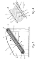
- Fig. 2 shows an enlarged section of the system with moving tongues 6, 7 and guide elements 5', in which vectors also appear that point out the air speed at the different passage planes between the tongues 6, 7 and the guide elements 5'.
- VA air absolute speed
- VR relative speed
- V sliding speed
- the previously-shown power values correspond to a balance situation between the sum of the thrusts exerted by the wind onto the tongues and the resisting torque (or torques) exerted in the exit areas of the structure 2.
- the tongues will start accelerating, keeping however the motion direction unchanged. Since also the wind direction is unchanged, at least at the beginning of the transient, the unavoidable consequence is a modulus decrease, and a direction modification as regards the relative air speed with respect to forward tongues 6.
- the direction modification in turn implies the presence of a relative speed component, that is normal to the tongue surface, that unavoidably creates vorticities, with following kinetic energy loss and pressure increase in the transit air.
- the device 1 tends to accelerate, without reaching its runaway speed. This can be acceptable, though within certain limits (for example: dynamo supplying batteries or electrolytic baths), or cannot be acceptable (for example: alternator connected to mains). But it is anyway necessary to provide for an entry flow rate adjusting system.
- a first possible adjusting arrangement (not shown) is providing that the whole structure 2 is installed on a platform that turns around a vertical axis, so that the platform, equipped with a suitable mechanisation, can be handled by operators or automatic systems to adjust its exposure to the wind. It will probably be suitable, in other cases, that the device 1 is able to be oriented by the same wind action, so that it anyway gives the wind its maximum working surface. In these cases, the adjustments will have to be given to another automatic member, as mentioned below.
- a similar rotating platform has without doubts less stability and safety problems with respect to orienting systems for large fans with horizontal axes.
- a second adjusting system provides for the device 1 to be equipped at its entry (see Fig. 3 and 4) with a partitioning system composed of a plurality of tongues 11 able to be oriented and arranged along the device 1 surface that is directly exposed to the wind. If for example the machine will be used to supply alternators connected to the electric mains, a constant tongue speed must be ensured when the load changes.
- the device 1 After having therefore discovered, based on environmental surveys, which is the most frequent wind speed in the installation area, the device 1 will have to be designed so that the rated power required to the plant corresponds to such speed (or to a reasonably lower speed if the periods of use have to be prolonged), and that, in case of stronger wind, the air flow rate is automatically decreased by differently orienting the tongues 11 of the partitioning system, or the rotating platform, or both.
- the device 1 can work within a given speed range (if a dynamo is used, for example).
- the automatic device for actuating the partitioning tongues 11 can be based on the moving tongues speed, thereby operating in order to keep such speed within the range required by users characteristics.
- a third adjusting system can finally provide for the possible variation of the slant of the device 1 front with respect to the horizon, making the device 1 itself rotatable around one of its horizontal axes, for example the lower one. This can be useful among others in case of exceptionally strong wind, to more or less "bend" the device 1 in order to reduce its front side exposed to the wind and the stresses to structure and foundations.
- a protection can be provied in the air exit area from the structure 2 from the direct wind action. This, if one one hand allows an undisturbed air exit from the device 1, on the other hand generates, as well known, a pressure increase in this area, that can be useful since also the air coming from the device 1, having lost its speed, depending on the already mentioned theory of stationary currents, certainly gains as regards density and pressure.
- the device 1 of the invention is equipped with at least one wind speed sensor (not shown) and a user machine speed sensor (not shown), in order to arrange an electronic control and command part that, depending on detected speeds, allows orienting the device 1 in the most efficient way.
- runaway speed can be used in the starting manoeuvres of the device 1, starting it at no-load till such speed is reached and then gradually inserting the users (for example through a clutch device) with the following gradual slowing of the device down to its operating speed.
Landscapes
- Engineering & Computer Science (AREA)
- Combustion & Propulsion (AREA)
- Life Sciences & Earth Sciences (AREA)
- Sustainable Development (AREA)
- Sustainable Energy (AREA)
- Chemical & Material Sciences (AREA)
- Mechanical Engineering (AREA)
- General Engineering & Computer Science (AREA)
- Aviation & Aerospace Engineering (AREA)
- Wind Motors (AREA)
- Linear Motors (AREA)
- Storing, Repeated Paying-Out, And Re-Storing Of Elongated Articles (AREA)
- Winding Of Webs (AREA)
- Turbine Rotor Nozzle Sealing (AREA)
Claims (11)
- Statische Windangetriebene (1) Vorrichtung, die einschließt:- eine Trägerstruktur (2), die den Ein- und Ausgang des Windes ermöglicht; und- ein Antriebselement mit Flügeln (3), das sich innerhalb der genannten Trägerstruktur (2) befindet, um vom Wind durchquert und in Bewegung gehalten zu werden, das genannte Antriebselement (3) ist in einer geschlossenen Ringkonfiguration realisiert und dreht sich um mindestens ein Paar verzahnter Riemenscheiben (4, 4'), die darunter liegenden Verbrauchermaschinen Energie übermitteln sollen, die genannten Riemenscheiben (4, 4') dienen dazu, um Achsen herumzudrehen, deren gegenseitige Position man durch Steuerung im Raum ändern kann, das genannte Antriebselement (3) ist um den inneren Luftübertragungsbereich (5) herum angebracht und besteht aus mehreren Vorlauf- (6) und mehreren Rücklaufrippen (7) und mindestens zwei Umkehrbereichen mit Rippen (8, 9), die die genannten Vorlauf- (6) und die genannten Rücklaufrippen (7) miteinander verbinden sollen;die genannte Vorrichtung (1) ist außerdem mit mehreren Teilrippen (11) ausgestattet, die oberhalb der vielen Vorlaufrippen (6) angebracht sind, um die Windstärke am Eingang der genannten Vorrichtung (1) zu reduzieren, die genannten Teilrippen (11) dienen dazu, gedreht zu werden, um dem Wind einen variablen Eingangswinkel zu bieten.
- Vorrichtung (1) gemäß Patentanspruch 1, die dadurch gekennzeichnet ist, dass die vielen Vorlauf- (6) und die vielen Rücklaufrippen (7) von einem oder mehreren Trägerelementen (10) mit geschlossenem Ring getragen werden und dazu dienen, einen anderen Winkel als 0° zwischen ihrer longitudinalen Symmetriefläche und der Windein- und ausgangsrichtung zu bilden.
- Vorrichtung (1) gemäß Patentanspruch 2, die dadurch gekennzeichnet ist, dass der von der longitudinalen Symmetriefläche der Vorlaufrippen (6) und von der Windeingangsrichtung gebildete Winkel anders als der von der longitudinalen Symmetriefläche der Rücklaufrippen (7) und der Windausgangsrichtung gebildete Winkel ist.
- Vorrichtung (1) gemäß Patentanspruch 1, die dadurch gekennzeichnet ist, dass der genannte innere Luftübertragungsbereich (5) mit mehreren Führungselementen (5') ausgestattet ist, deren longitudinale Symmetriefläche mit der Windeingangsrichtung einen anderen Winkel als 0° bildet.
- Vorrichtung (1) gemäß Patentanspruch 2, 3 oder 4, die dadurch gekennzeichnet ist, dass die von den longitudinalen Achsen der Vorlaufrippen (6), der Rücklaufrippen (7) und der Führungselemente (5') mit der Windrichtung gebildeten Winkel alle untereinander verschieden sind.
- Vorrichtung (1) gemäß einem beliebigen der vorhergehenden Patentansprüche, die dadurch gekennzeichnet ist, dass die genannte Struktur (2) auf einer um eine vertikale Achse drehbaren Plattform installiert ist, so dass die genannte Struktur (2) so ausgerichtet werden kann, dass sie dem Wind die maximale Nutzfläche zeigt oder dass sie bei starkem Wind die Exposition vermindert.
- Vorrichtung (1) gemäß einem beliebigen der vorhergehenden Patentansprüche, die dadurch gekennzeichnet ist, dass der Winkel zwischen der mittleren Fläche der Vorrichtung (1) und dem Horizont je nach der Windstärke und den Anforderungen des Benutzers geändert und eingestellt werden kann.
- Vorrichtung (1) gemäß einem beliebigen der vorhergehenden Patentansprüche, die dadurch gekennzeichnet ist, dass die genannte Vorrichtung (1) dazu dient, die Neigung ihrer Vorderseite gegenüber dem Horizont zu ändern, die Vorrichtung (1) dreht sich um eine ihrer horizontalen Achsen, zum Beispiel um die untere.
- Vorrichtung (1) gemäß einem beliebigen der vorhergehenden Patentansprüche, die dadurch gekennzeichnet ist, dass sie außerdem mit mindestens einem Windgeschwindigkeitssensor und einem Geschwindigkeitssensor der Verbrauchermaschine ausgestattet ist, die genannte Vorrichtung (1) wird durch einen elektronisch kontrollierten und gesteuerten Teil überwacht, der je nach den festgestellten Geschwindigkeiten die automatische Einstellung der Vorrichtung (1) gemäß den Anwendungen ermöglicht.
- Vorrichtung (1) gemäß einem beliebigen der vorhergehenden Patentansprüche, die dadurch gekennzeichnet ist, dass sie dazu dient, operativ auf andere Vorrichtungen (1) der gleichen Art gestapelt und verwendet zu werden.
- Vorrichtung (1) gemäß einem beliebigen der Patentansprüche von 1 bis 10, die dadurch gekennzeichnet ist, dass sie dazu dient, operativ neben und parallel zu anderen Vorrichtungen (1) der gleichen Art verwendet zu werden.
Applications Claiming Priority (2)
| Application Number | Priority Date | Filing Date | Title |
|---|---|---|---|
| IT2001TO000492A ITTO20010492A1 (it) | 2001-05-24 | 2001-05-24 | Dispositivo statico a propulsione eolica. |
| ITTO20010492 | 2001-05-24 |
Publications (2)
| Publication Number | Publication Date |
|---|---|
| EP1260708A1 EP1260708A1 (de) | 2002-11-27 |
| EP1260708B1 true EP1260708B1 (de) | 2007-06-13 |
Family
ID=11458889
Family Applications (1)
| Application Number | Title | Priority Date | Filing Date |
|---|---|---|---|
| EP02011157A Expired - Lifetime EP1260708B1 (de) | 2001-05-24 | 2002-05-21 | Endlosbandwindturbine |
Country Status (6)
| Country | Link |
|---|---|
| EP (1) | EP1260708B1 (de) |
| AT (1) | ATE364789T1 (de) |
| DE (1) | DE60220585T2 (de) |
| ES (1) | ES2289029T3 (de) |
| IT (1) | ITTO20010492A1 (de) |
| PT (1) | PT1260708E (de) |
Families Citing this family (5)
| Publication number | Priority date | Publication date | Assignee | Title |
|---|---|---|---|---|
| RU2296881C2 (ru) * | 2004-11-22 | 2007-04-10 | Леонид Яковлевич Дубовский | Способ преобразования энергии потока среды и энергопреобразующее устройство для его осуществления (варианты) |
| WO2016179591A1 (en) * | 2015-05-07 | 2016-11-10 | Schneider Abraham D | Hydraulic turbine |
| DE102016010416A1 (de) * | 2016-08-30 | 2018-03-01 | Johann-Marius Milosiu | Verbesserte Windkraftanlage mit linearer Turbine |
| LV15594B (lv) * | 2020-03-06 | 2023-09-20 | Saņņikovs Vladimirs | Jauna tehnoloģija un ierīces atmosfēras vēja enerģijas savākšanai un koncentrēšanai turbīnas priekšā |
| DE202023104396U1 (de) | 2023-08-03 | 2024-11-05 | Brocks Renewable Energies Gmbh | Windkraftanlage |
Family Cites Families (7)
| Publication number | Priority date | Publication date | Assignee | Title |
|---|---|---|---|---|
| US4049300A (en) * | 1974-06-26 | 1977-09-20 | Schneider Daniel J | Fluid driven power producing apparatus |
| US4186314A (en) * | 1976-07-23 | 1980-01-29 | Diggs Richard E | High efficiency wind power machine |
| US4134469A (en) * | 1976-10-08 | 1979-01-16 | Turbopanel Motors, Inc. | Linear turbine |
| FR2493416A1 (fr) * | 1980-10-30 | 1982-05-07 | Choy Jean Pierre | Panneau eolien domestique |
| US4536125A (en) * | 1983-04-25 | 1985-08-20 | George R. Herman | Wind lift generator |
| EP0259393A1 (de) * | 1986-02-25 | 1988-03-16 | LANGE, Horst | Einrichtung zur umwandlung von energie |
| IE20000082A1 (en) * | 1999-01-29 | 2001-01-24 | David Callaghan | Flow energy converter |
-
2001
- 2001-05-24 IT IT2001TO000492A patent/ITTO20010492A1/it unknown
-
2002
- 2002-05-21 EP EP02011157A patent/EP1260708B1/de not_active Expired - Lifetime
- 2002-05-21 DE DE60220585T patent/DE60220585T2/de not_active Expired - Fee Related
- 2002-05-21 AT AT02011157T patent/ATE364789T1/de not_active IP Right Cessation
- 2002-05-21 PT PT02011157T patent/PT1260708E/pt unknown
- 2002-05-21 ES ES02011157T patent/ES2289029T3/es not_active Expired - Lifetime
Also Published As
| Publication number | Publication date |
|---|---|
| PT1260708E (pt) | 2007-10-02 |
| ITTO20010492A1 (it) | 2001-08-24 |
| DE60220585D1 (de) | 2007-07-26 |
| ES2289029T3 (es) | 2008-02-01 |
| DE60220585T2 (de) | 2008-02-14 |
| EP1260708A1 (de) | 2002-11-27 |
| ATE364789T1 (de) | 2007-07-15 |
Similar Documents
| Publication | Publication Date | Title |
|---|---|---|
| US6932561B2 (en) | Power generation system | |
| US7094017B2 (en) | Vertical shaft driving device for vertical wind mills or the like and electric power generator using the same | |
| US5512788A (en) | Exhaust air recovery system | |
| US8257020B2 (en) | Wind turbine system for buildings | |
| US8076791B2 (en) | Wind and water turbine | |
| US8253264B2 (en) | Orbiting drum wind turbine and method for the generation of electrical power from wind energy | |
| US20100213722A1 (en) | Wind turbine generators | |
| US4636707A (en) | Power generating equipment | |
| CA2409509A1 (en) | Azimuth drive for wind energy plants | |
| EP1260708B1 (de) | Endlosbandwindturbine | |
| IL188721A (en) | Electricity generating apparatus from a flow of water such as tide, river or the like | |
| GB2432208A (en) | Ventilation control | |
| AU3851597A (en) | An eolian systems for energy production | |
| WO2000028210A1 (en) | Generation of energy with fluid | |
| WO2022195595A1 (en) | Wave energy conversion system | |
| EP1686262A2 (de) | Hydroelektrischer Generator | |
| US5249923A (en) | Water actuated outdoor fan | |
| KR20170041851A (ko) | 해류 발전 장치의 기동 방법 및 기동 제어 장치 | |
| JP2022017805A (ja) | 流体発電システム及びその設置構造 | |
| US5575587A (en) | Tide-operated driving system | |
| JPH023002B2 (de) | ||
| KR102321192B1 (ko) | 풍력을 이용한 동력발생장치 | |
| EP0787901B1 (de) | Durch Windkraft angetriebener Generator | |
| US3899268A (en) | Wind-driven motive apparatus | |
| CN115853701B (zh) | 潮流集束设备及潮流发电装置 |
Legal Events
| Date | Code | Title | Description |
|---|---|---|---|
| PUAI | Public reference made under article 153(3) epc to a published international application that has entered the european phase |
Free format text: ORIGINAL CODE: 0009012 |
|
| AK | Designated contracting states |
Kind code of ref document: A1 Designated state(s): AT BE CH CY DE DK ES FI FR GB GR IE IT LI LU MC NL PT SE TR |
|
| AX | Request for extension of the european patent |
Free format text: AL;LT;LV;MK;RO;SI |
|
| 17P | Request for examination filed |
Effective date: 20030502 |
|
| AKX | Designation fees paid |
Designated state(s): AT BE CH CY DE DK ES FI FR GB GR IE IT LI LU MC NL PT SE TR |
|
| GRAP | Despatch of communication of intention to grant a patent |
Free format text: ORIGINAL CODE: EPIDOSNIGR1 |
|
| GRAS | Grant fee paid |
Free format text: ORIGINAL CODE: EPIDOSNIGR3 |
|
| GRAA | (expected) grant |
Free format text: ORIGINAL CODE: 0009210 |
|
| AK | Designated contracting states |
Kind code of ref document: B1 Designated state(s): AT BE CH CY DE DK ES FI FR GB GR IE IT LI LU MC NL PT SE TR |
|
| PG25 | Lapsed in a contracting state [announced via postgrant information from national office to epo] |
Ref country code: LI Free format text: LAPSE BECAUSE OF FAILURE TO SUBMIT A TRANSLATION OF THE DESCRIPTION OR TO PAY THE FEE WITHIN THE PRESCRIBED TIME-LIMIT Effective date: 20070613 Ref country code: CH Free format text: LAPSE BECAUSE OF FAILURE TO SUBMIT A TRANSLATION OF THE DESCRIPTION OR TO PAY THE FEE WITHIN THE PRESCRIBED TIME-LIMIT Effective date: 20070613 |
|
| REG | Reference to a national code |
Ref country code: GB Ref legal event code: FG4D |
|
| REG | Reference to a national code |
Ref country code: CH Ref legal event code: EP |
|
| REG | Reference to a national code |
Ref country code: IE Ref legal event code: FG4D |
|
| REF | Corresponds to: |
Ref document number: 60220585 Country of ref document: DE Date of ref document: 20070726 Kind code of ref document: P |
|
| PG25 | Lapsed in a contracting state [announced via postgrant information from national office to epo] |
Ref country code: SE Free format text: LAPSE BECAUSE OF FAILURE TO SUBMIT A TRANSLATION OF THE DESCRIPTION OR TO PAY THE FEE WITHIN THE PRESCRIBED TIME-LIMIT Effective date: 20070913 |
|
| REG | Reference to a national code |
Ref country code: PT Ref legal event code: SC4A Free format text: AVAILABILITY OF NATIONAL TRANSLATION Effective date: 20070911 |
|
| REG | Reference to a national code |
Ref country code: GR Ref legal event code: EP Ref document number: 20070402785 Country of ref document: GR |
|
| PG25 | Lapsed in a contracting state [announced via postgrant information from national office to epo] |
Ref country code: AT Free format text: LAPSE BECAUSE OF FAILURE TO SUBMIT A TRANSLATION OF THE DESCRIPTION OR TO PAY THE FEE WITHIN THE PRESCRIBED TIME-LIMIT Effective date: 20070613 |
|
| NLV1 | Nl: lapsed or annulled due to failure to fulfill the requirements of art. 29p and 29m of the patents act | ||
| REG | Reference to a national code |
Ref country code: CH Ref legal event code: PL |
|
| PG25 | Lapsed in a contracting state [announced via postgrant information from national office to epo] |
Ref country code: BE Free format text: LAPSE BECAUSE OF FAILURE TO SUBMIT A TRANSLATION OF THE DESCRIPTION OR TO PAY THE FEE WITHIN THE PRESCRIBED TIME-LIMIT Effective date: 20070613 |
|
| PG25 | Lapsed in a contracting state [announced via postgrant information from national office to epo] |
Ref country code: NL Free format text: LAPSE BECAUSE OF FAILURE TO SUBMIT A TRANSLATION OF THE DESCRIPTION OR TO PAY THE FEE WITHIN THE PRESCRIBED TIME-LIMIT Effective date: 20070613 |
|
| REG | Reference to a national code |
Ref country code: ES Ref legal event code: FG2A Ref document number: 2289029 Country of ref document: ES Kind code of ref document: T3 |
|
| EN | Fr: translation not filed | ||
| PLBE | No opposition filed within time limit |
Free format text: ORIGINAL CODE: 0009261 |
|
| STAA | Information on the status of an ep patent application or granted ep patent |
Free format text: STATUS: NO OPPOSITION FILED WITHIN TIME LIMIT |
|
| PG25 | Lapsed in a contracting state [announced via postgrant information from national office to epo] |
Ref country code: DK Free format text: LAPSE BECAUSE OF FAILURE TO SUBMIT A TRANSLATION OF THE DESCRIPTION OR TO PAY THE FEE WITHIN THE PRESCRIBED TIME-LIMIT Effective date: 20070613 |
|
| 26N | No opposition filed |
Effective date: 20080314 |
|
| PG25 | Lapsed in a contracting state [announced via postgrant information from national office to epo] |
Ref country code: FR Free format text: LAPSE BECAUSE OF FAILURE TO SUBMIT A TRANSLATION OF THE DESCRIPTION OR TO PAY THE FEE WITHIN THE PRESCRIBED TIME-LIMIT Effective date: 20080208 |
|
| PG25 | Lapsed in a contracting state [announced via postgrant information from national office to epo] |
Ref country code: MC Free format text: LAPSE BECAUSE OF NON-PAYMENT OF DUE FEES Effective date: 20080531 |
|
| GBPC | Gb: european patent ceased through non-payment of renewal fee |
Effective date: 20080521 |
|
| PG25 | Lapsed in a contracting state [announced via postgrant information from national office to epo] |
Ref country code: FI Free format text: LAPSE BECAUSE OF FAILURE TO SUBMIT A TRANSLATION OF THE DESCRIPTION OR TO PAY THE FEE WITHIN THE PRESCRIBED TIME-LIMIT Effective date: 20070613 |
|
| PG25 | Lapsed in a contracting state [announced via postgrant information from national office to epo] |
Ref country code: IE Free format text: LAPSE BECAUSE OF NON-PAYMENT OF DUE FEES Effective date: 20080521 |
|
| PG25 | Lapsed in a contracting state [announced via postgrant information from national office to epo] |
Ref country code: GB Free format text: LAPSE BECAUSE OF NON-PAYMENT OF DUE FEES Effective date: 20080521 |
|
| PG25 | Lapsed in a contracting state [announced via postgrant information from national office to epo] |
Ref country code: CY Free format text: LAPSE BECAUSE OF FAILURE TO SUBMIT A TRANSLATION OF THE DESCRIPTION OR TO PAY THE FEE WITHIN THE PRESCRIBED TIME-LIMIT Effective date: 20070613 |
|
| PGFP | Annual fee paid to national office [announced via postgrant information from national office to epo] |
Ref country code: ES Payment date: 20090514 Year of fee payment: 8 |
|
| PGFP | Annual fee paid to national office [announced via postgrant information from national office to epo] |
Ref country code: DE Payment date: 20090529 Year of fee payment: 8 Ref country code: IT Payment date: 20090512 Year of fee payment: 8 Ref country code: PT Payment date: 20090521 Year of fee payment: 8 |
|
| PGFP | Annual fee paid to national office [announced via postgrant information from national office to epo] |
Ref country code: GR Payment date: 20090429 Year of fee payment: 8 |
|
| PG25 | Lapsed in a contracting state [announced via postgrant information from national office to epo] |
Ref country code: LU Free format text: LAPSE BECAUSE OF NON-PAYMENT OF DUE FEES Effective date: 20080521 |
|
| PG25 | Lapsed in a contracting state [announced via postgrant information from national office to epo] |
Ref country code: TR Free format text: LAPSE BECAUSE OF FAILURE TO SUBMIT A TRANSLATION OF THE DESCRIPTION OR TO PAY THE FEE WITHIN THE PRESCRIBED TIME-LIMIT Effective date: 20070613 |
|
| REG | Reference to a national code |
Ref country code: PT Ref legal event code: MM4A Free format text: LAPSE DUE TO NON-PAYMENT OF FEES Effective date: 20101122 |
|
| PG25 | Lapsed in a contracting state [announced via postgrant information from national office to epo] |
Ref country code: PT Free format text: LAPSE BECAUSE OF NON-PAYMENT OF DUE FEES Effective date: 20101122 |
|
| PG25 | Lapsed in a contracting state [announced via postgrant information from national office to epo] |
Ref country code: GR Free format text: LAPSE BECAUSE OF NON-PAYMENT OF DUE FEES Effective date: 20101202 Ref country code: IT Free format text: LAPSE BECAUSE OF NON-PAYMENT OF DUE FEES Effective date: 20100521 |
|
| PG25 | Lapsed in a contracting state [announced via postgrant information from national office to epo] |
Ref country code: DE Free format text: LAPSE BECAUSE OF NON-PAYMENT OF DUE FEES Effective date: 20101201 |
|
| REG | Reference to a national code |
Ref country code: ES Ref legal event code: FD2A Effective date: 20110712 |
|
| PG25 | Lapsed in a contracting state [announced via postgrant information from national office to epo] |
Ref country code: ES Free format text: LAPSE BECAUSE OF NON-PAYMENT OF DUE FEES Effective date: 20110630 |
|
| PG25 | Lapsed in a contracting state [announced via postgrant information from national office to epo] |
Ref country code: ES Free format text: LAPSE BECAUSE OF NON-PAYMENT OF DUE FEES Effective date: 20100522 |