EP1260766B1 - Verfahren zur Anpassung eines brennerbeheizten Heizgerätes an ein Luft-Abgassystem - Google Patents
Verfahren zur Anpassung eines brennerbeheizten Heizgerätes an ein Luft-Abgassystem Download PDFInfo
- Publication number
- EP1260766B1 EP1260766B1 EP02010791A EP02010791A EP1260766B1 EP 1260766 B1 EP1260766 B1 EP 1260766B1 EP 02010791 A EP02010791 A EP 02010791A EP 02010791 A EP02010791 A EP 02010791A EP 1260766 B1 EP1260766 B1 EP 1260766B1
- Authority
- EP
- European Patent Office
- Prior art keywords
- speed
- air
- blower
- pressure value
- burner
- Prior art date
- Legal status (The legal status is an assumption and is not a legal conclusion. Google has not performed a legal analysis and makes no representation as to the accuracy of the status listed.)
- Expired - Lifetime
Links
- 238000000034 method Methods 0.000 title claims abstract description 11
- UGFAIRIUMAVXCW-UHFFFAOYSA-N Carbon monoxide Chemical compound [O+]#[C-] UGFAIRIUMAVXCW-UHFFFAOYSA-N 0.000 title description 2
- 239000003546 flue gas Substances 0.000 title 1
- 238000012937 correction Methods 0.000 claims abstract description 7
- 238000005259 measurement Methods 0.000 claims description 6
- 230000001419 dependent effect Effects 0.000 claims 1
- 238000011144 upstream manufacturing Methods 0.000 claims 1
- 238000009529 body temperature measurement Methods 0.000 abstract 1
- 238000002485 combustion reaction Methods 0.000 description 4
- 238000010438 heat treatment Methods 0.000 description 4
- 238000009434 installation Methods 0.000 description 4
- 238000010586 diagram Methods 0.000 description 3
- 229910002091 carbon monoxide Inorganic materials 0.000 description 2
- 238000009833 condensation Methods 0.000 description 1
- 230000005494 condensation Effects 0.000 description 1
- 230000007423 decrease Effects 0.000 description 1
- 239000003344 environmental pollutant Substances 0.000 description 1
- 238000009533 lab test Methods 0.000 description 1
- 238000012544 monitoring process Methods 0.000 description 1
- 231100000719 pollutant Toxicity 0.000 description 1
- 238000010926 purge Methods 0.000 description 1
Images

Classifications
-
- F—MECHANICAL ENGINEERING; LIGHTING; HEATING; WEAPONS; BLASTING
- F23—COMBUSTION APPARATUS; COMBUSTION PROCESSES
- F23N—REGULATING OR CONTROLLING COMBUSTION
- F23N3/00—Regulating air supply or draught
- F23N3/08—Regulating air supply or draught by power-assisted systems
- F23N3/082—Regulating air supply or draught by power-assisted systems using electronic means
-
- F—MECHANICAL ENGINEERING; LIGHTING; HEATING; WEAPONS; BLASTING
- F23—COMBUSTION APPARATUS; COMBUSTION PROCESSES
- F23N—REGULATING OR CONTROLLING COMBUSTION
- F23N1/00—Regulating fuel supply
- F23N1/06—Regulating fuel supply conjointly with draught
- F23N1/062—Regulating fuel supply conjointly with draught using electronic means
-
- F—MECHANICAL ENGINEERING; LIGHTING; HEATING; WEAPONS; BLASTING
- F23—COMBUSTION APPARATUS; COMBUSTION PROCESSES
- F23N—REGULATING OR CONTROLLING COMBUSTION
- F23N5/00—Systems for controlling combustion
- F23N5/18—Systems for controlling combustion using detectors sensitive to rate of flow of air or fuel
- F23N5/184—Systems for controlling combustion using detectors sensitive to rate of flow of air or fuel using electronic means
-
- F—MECHANICAL ENGINEERING; LIGHTING; HEATING; WEAPONS; BLASTING
- F23—COMBUSTION APPARATUS; COMBUSTION PROCESSES
- F23N—REGULATING OR CONTROLLING COMBUSTION
- F23N5/00—Systems for controlling combustion
- F23N5/18—Systems for controlling combustion using detectors sensitive to rate of flow of air or fuel
- F23N2005/181—Systems for controlling combustion using detectors sensitive to rate of flow of air or fuel using detectors sensitive to rate of flow of air
- F23N2005/182—Air flow switch
-
- F—MECHANICAL ENGINEERING; LIGHTING; HEATING; WEAPONS; BLASTING
- F23—COMBUSTION APPARATUS; COMBUSTION PROCESSES
- F23N—REGULATING OR CONTROLLING COMBUSTION
- F23N2225/00—Measuring
- F23N2225/04—Measuring pressure
-
- F—MECHANICAL ENGINEERING; LIGHTING; HEATING; WEAPONS; BLASTING
- F23—COMBUSTION APPARATUS; COMBUSTION PROCESSES
- F23N—REGULATING OR CONTROLLING COMBUSTION
- F23N2225/00—Measuring
- F23N2225/08—Measuring temperature
- F23N2225/19—Measuring temperature outlet temperature water heat-exchanger
-
- F—MECHANICAL ENGINEERING; LIGHTING; HEATING; WEAPONS; BLASTING
- F23—COMBUSTION APPARATUS; COMBUSTION PROCESSES
- F23N—REGULATING OR CONTROLLING COMBUSTION
- F23N2225/00—Measuring
- F23N2225/08—Measuring temperature
- F23N2225/20—Measuring temperature entrant temperature
-
- F—MECHANICAL ENGINEERING; LIGHTING; HEATING; WEAPONS; BLASTING
- F23—COMBUSTION APPARATUS; COMBUSTION PROCESSES
- F23N—REGULATING OR CONTROLLING COMBUSTION
- F23N2227/00—Ignition or checking
- F23N2227/02—Starting or ignition cycles
-
- F—MECHANICAL ENGINEERING; LIGHTING; HEATING; WEAPONS; BLASTING
- F23—COMBUSTION APPARATUS; COMBUSTION PROCESSES
- F23N—REGULATING OR CONTROLLING COMBUSTION
- F23N2233/00—Ventilators
- F23N2233/02—Ventilators in stacks
- F23N2233/04—Ventilators in stacks with variable speed
Definitions
- the invention relates to a method for adapting a burner-heated heater according to the preamble of claim 1.
- This method is based on the defined dependence of the air volume flow on the speed of the fan.
- this defined dependency only applies to a constant air temperature.
- the burner must have been out of operation for a certain minimum time prior to any automatic tube length adjustment to ensure reproducible air temperatures during tube length adjustment. This requirement is of particular importance for a pressure measuring system on the exhaust side.
- the aim of the invention is to avoid this disadvantage and to provide a method of the type mentioned, which can also be used in a warm operating state of the heater.
- a tube length adjustment can be carried out even in the warm state of the heater, as by the operation of the blower with a certain Vor Hughesnaviere before the actual determination of the speed at which the intended for the release of the gas supply pressure value is reached, the residual heat after a shutdown of the burner away from the primary heat exchanger and is discharged past the pressure measuring system.
- the temperature of the air volume flow at the pressure measuring system equals the measured flow or return temperature of the primary heat exchanger in the device. As a result, it can be concluded from the measured flow or return temperature to the temperature of the air volume flow. With the aid of the calculated temperature correction function, the speed determined in the warm device state can be corrected to a defined value.
- the tube length adjustment can be made almost immediately after the burner is shut down, with the time during which the blower operates at a certain pre-purging speed being relatively short, e.g. 1 min, can be kept.
- the heater 23 after the Fig. 1 has a burner 16 which is arranged in a chamber 25 which is connected via a fresh air supply 20 which coaxially surrounds an exhaust gas guide 11, with the environment.
- This burner 16 acts on a heat exchanger 13, which is connected via a return line 17 and a flow line 15 with a radiator assembly.
- an exhaust gas collecting hood 12 is arranged, which is connected to the exhaust gas guide 11.
- the burner 16 can be connected via a gas line 10 and a gas control device 18 to a gas supply 19.
- the gas control device 18 is provided with a modulation magnet 9, which provides the corresponding drive.
- this modulation magnet 9 is controlled by a control electronics 7, which is connected via a control line 8 with the modulation magnet 9.
- a fan 3 is arranged, the speed of which is monitored by a Hall sensor 2.
- This Hall sensor 2 is connected via a signal line 5 to a speed controller 22.
- the control electronics 7 is connected via a control line 6 to the speed controller 22, which in turn is connected via power supply lines 21 to the blower 3.
- a pressure measuring point 14 is arranged, which is connected to a pressure switch 1, which switches when a certain pressure is reached.
- the pressure in the exhaust gas guide 11 is detected via the pressure measuring point 14, which may be formed by a pitot tube.
- the pressure switch 1 is connected to the control electronics 7.
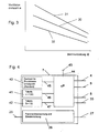
- Fig. 3 represented standard characteristic curve 30 - speed as a function of the burner power Q - is determined from the Lucasiereangins of the device with regard to condensation behavior, pollutant freedom and flame stability under standard conditions in laboratory experiments and stored as table 41 in the control electronics 7 ( Fig. 4 ).
- This standard characteristic 30 represents the course in which optimum emission values result under standard installation conditions. To determine the burner 16 is put into operation and varied the load over the entire modulation range. At each operating point, the speed is then determined, in which the CO and NO x emissions reach the required values, the over-ignition is still guaranteed and, secondly, no condensate is produced in the exhaust pipe.
- the operating characteristic curve is calculated from the standard characteristic curve by multiplying by the ratio "speed in pressure switch point" to "speed in pressure switch point under standard conditions". The latter is determined as the standard characteristic under standard conditions and stored in the memory 40 of the control electronics 7.
- Typical characteristics shows the Fig. 3 , wherein the standard characteristic 30 with the installation according to Fig. 2a correlates, the operating characteristic 31 with Fig. 2b and the operating characteristic 32 with Fig. 2c ,
- a heater 23 may be provided with differently shaped air-exhaust systems 24, which are formed by a fresh air supply 20 and an enclosed by this exhaust guide 11, and a blower 3.
- the air-exhaust system 24 angled ( Fig. 2a, 2b ) or straight ( Fig. 2c ).
- the length of the air exhaust system 24 can vary considerably ( Fig. 2a, 2b ), which results in significant differences in the flow resistance of the air-exhaust system 24.
- a correction factor is determined, with the operating characteristic curves 30 are determined from the stored in the control electronics 7 standard characteristics.
- the control of the modulating magnet 9 and thus the gas supply to the burner 16 and the rotational speed of the blower 3 is controlled by the control electronics 7 according to these operating characteristics.
- the control deviation is defined as the deviation of the actual flow temperature, measured by the temperature sensor 34 to the set target value, that of the controller 7 via the adjuster 43 is given.
- This adjuster 43 may be an outside temperature sensor, which is connected via a line 44 to a microprocessor uP of the controller 7, or a fixed value.
- the microprocessor ⁇ P has access to all tables via data lines 45, 46 and 47. Furthermore, the microprocessor ⁇ P is connected to all actual values and the nominal value transmitter via signal lines 33.
- controller 7 has a flame monitoring and ignition device 28, which is connected via lines 27 and 29 with a sensor, not shown, and an electrode, also not shown.
- the edge characteristics 31 and 32 set the highest and lowest speed, so that within the field between these limit characteristics safe burner operation is possible. Too high an excess of air would lead to a lifting of the flames and thus to an imperfect combustion and a too small air flow equally to incomplete combustion with carbon monoxide fractions.
- a correction factor is determined, with the operating characteristic curves are calculated from the stored in the controller 7 standard characteristics.
- the control of the modulating magnet 9 and thus the gas supply to the burner 16 and the rotational speed of the blower 3 is controlled by the controller 7 according to these operating characteristics.
- the fan 3 is kept for a certain minimum time, e.g. may be one minute, is operated at its maximum speed or power, whereby the temperature of the air volume flow at the pressure measuring system, the measured in the device measured flow temperature of the primary heat exchanger, so that depending on the measured flow and / or return temperature of the primary Heat exchanger can be closed to the temperature of the air flow.
- the speed of the fan 3 is lowered to the starting speed and then increased slowly until the intended pressure value is reached.
- a temperature correction function is calculated from the result of a measurement of the flow and / or return temperature of the primary heat exchanger 13, with the calculated speed from which a corrected speed is calculated, which is used to determine the operating characteristics.
Landscapes
- Engineering & Computer Science (AREA)
- Chemical & Material Sciences (AREA)
- Combustion & Propulsion (AREA)
- Mechanical Engineering (AREA)
- General Engineering & Computer Science (AREA)
- Regulation And Control Of Combustion (AREA)
- Air Supply (AREA)
- Chimneys And Flues (AREA)
- Sampling And Sample Adjustment (AREA)
Description
- Die Erfindung bezieht sich auf ein Verfahren zur Anpassung eines brennerbeheizten Heizgerätes gemäß dem Oberbegriff des Anspruches 1.
- Ein solches Verfahren wurde z.B. durch die
DE 198 47 448 A1 bekannt. - Dieses Verfahren basiert auf der definierten Abhängigkeit des Luftvolumenstromes von der Drehzahl des Gebläses. Diese definierte Abhängigkeit gilt jedoch nur für eine konstante Lufttemperatur. Aus diesem Grund muß bei dem bekannten Verfahren der Brenner vor jeder automatischen Rohrlängenanpassung für eine bestimmte Mindestzeit außer Betrieb gewesen sein, um reproduzierbare Lufttemperaturen während der Rohrlängenanpassung sicherzustellen. Diese Forderung ist für ein Druckmeßsystem an der Abgasseite von besonderer Bedeutung.
- In der Praxis kommen jedoch immer wieder Betriebssituationen vor, die eine solche Mindest-Stillstandszeit des Brenners nicht zulassen, wie beispielsweise bei einer Wiedereinschaltung nach einer Störabschaltung oder einer Schornsteinfeger-Messung nach einer Netzab- bzw. - zuschaltung. In einem solchen warmen Betriebszustand ist das bekannte Verfahren nicht einsetzbar.
- Ziel der Erfindung ist es, diesen Nachteil zu vermeiden und ein Verfahren der eingangs erwähnten Art anzugeben, das auch in einem warmen Betriebszustand des Heizgerätes eingesetzt werden kann.
- Erfindungsgemäß wird dies bei einem Verfahren der eingangs erwähnten Art durch die kennzeichnenden Merkmale des Anspruches 1 erreicht.
- Durch die vorgeschlagenen Verfahrensschritte kann eine Rohrlängenanpassung auch im warmen Zustand des Heizgerätes durchgeführt werden, da sich durch den Betrieb des Gebläses mit einer bestimmten Vorspüldrehzahl vor der eigentlichen Ermittlung der Drehzahl, bei der der für die Freigabe der Gaszufuhr vorgesehene Druckwert erreicht wird, die Restwärme nach einer Abschaltung des Brenners vom Primär-Wärmetauscher weg und am Druckmeßsystem vorbei abgeführt wird. Dabei gleicht sich die Temperatur des Luftvolumenstromes am Druckmeßsystem, der im Gerät gemessenen Vorlauf- oder Rücklauftemperatur des Primär-Wärmetauschers an. Dadurch kann von der gemessenen Vorlauf- oder Rücklauftemperatur auf die Temperatur des Luftvolumenstromes geschlossen werden. Mit Hilfe der errechneten Temperatur-Korrekturfunktion läßt sich die im warmen Gerätezustand ermittelte Drehzahl auf einen definierten Wert korrigieren.
- Durch die vorgeschlagenen Maßnahmen kann die Rohrlängenanpassung praktisch unmittelbar nach der Abschaltung des Brenners vorgenommen werden, wobei die Zeit, während der das Gebläse mit bestimmter Vorspüldrehzahl arbeitet, relativ kurz, z.B. 1 min, gehalten werden kann.
-
-
Fig. 1 schematisch eine gebläseunterstützte Heizeinrichtung, -
Fig. 2a bis 2c schematisch verschiedene Ausführungsformen eines Luft-Abgassystems für eine Heizeinrichtung nach derFig. 1 , -
Fig. 3 ein Diagramm und -
Fig. 4 eine Steuerelektronik. - Gleiche Bezugszeichen bedeuten in allen Figuren gleiche Einzelheiten.
- Die Heizeinrichtung 23 nach der
Fig. 1 weist einen Brenner 16 auf, der in einer Kammer 25 angeordnet ist, die über eine Frischluftzufuhr 20, die koaxial eine Abgasführung 11 umgibt, mit der Umgebung verbunden ist. Dieser Brenner 16 beaufschlagt einen Wärmetauscher 13, der über eine Rücklaufleitung 17 und eine Vorlaufleitung 15 mit einer Heizkörperanordnung verbunden ist. - Über dem Wärmetauscher 13 ist eine Abgassammelhaube 12 angeordnet, die mit der Abgasführung 11 verbunden ist.
- Der Brenner 16 ist über eine Gasleitung 10 und eine Gasregeleinrichtung 18 mit einer Gasversorgung 19 verbindbar. Die Gasregeleinrichtung 18 ist mit einem Modulationsmagneten 9 versehen, der für den entsprechenden Antrieb sorgt.
- Gesteuert ist dieser Modulationsmagnet 9 von einer Steuerelektronik 7, die über eine Steuerleitung 8 mit dem Modulationsmagnet 9 verbunden ist.
- In der Abgasführung 11 ist ein Gebläse 3 angeordnet, dessen Drehzahl von einem Hallsensor 2 überwacht ist. Dieser Hallsensor 2 ist über eine Signalleitung 5 mit einem Drehzahlregler 22 verbunden.
- Die Steuerelektronik 7 ist über eine Steuerleitung 6 mit dem Drehzahlregler 22 verbunden, der seinerseits über Spannungsversorgungsleitungen 21 mit dem Gebläse 3 verbunden ist.
- In der Abgasführung 11 ist eine Druckmeßstelle 14 angeordnet, die mit einem Druckschalter 1 verbunden ist, der bei Erreichen eines bestimmten Druckes schaltet. Dabei wird über die Druckmeßstelle 14, die durch ein Pitotrohr gebildet sein kann, der Druck in der Abgasführung 11 erfaßt. Über eine Signalleitung 4 ist der Druckschalter 1 mit der Steuerelektronik 7 verbunden.
- Die in
Fig. 3 dargestellte Standardkennlinie 30 - Drehzahl als Funktion der Brennerleistung Q - wird aus der Luftzahlanforderung des Gerätes hinsichtlich Kondensationsverhalten, Schadstofffreiheit und Flammenstabilität unter Standardbedingungen im Laborversuch ermittelt und als Tabelle 41 in der Steuerelektronik 7 abgelegt (Fig. 4 ). In derFig. 3 ist ein typischer Kennlinienverlauf dargestellt. Diese Standardkennlinie 30 stellt dabei den Verlauf dar, bei dem sich optimale Emissionswerte unter Standardinstallationsbedingungen ergeben. Zu ihrer Ermittlung wird der Brenner 16 in Betrieb genommen und die Belastung über den gesamten Modulationsbereich variiert. In jedem Betriebspunkt wird dann die Drehzahl ermittelt, in dem die CO- und NOx-Emissionen die geforderten Werte erreichen, die Überzündung noch gewährleistet ist und zum anderen im Abgasrohr noch kein Kondensat anfällt. - Weichen die Installationsbedingungen hinsichtlich Abgasführung von den Standardinstallationsbedingungen ab, so werden durch die veränderten Widerstände andere Drehzahlen notwendig, um gleiche Luftzahlverhältnisse zu erhalten. Ein Maß für diese Abweichung ist die Drehzahl, bei der der Druckdosenschaltpunkt erreicht wird. Damit errechnet sich die Betriebskennlinie aus der Standardkennlinie durch Multiplikation mit dem Verhältnis "Drehzahl im Druckdosenschaltpunkt" zur "Drehzahl im Druckdosenschaltpunkt unter Standardbedingungen". Letztere wird wie die Standardkennlinie unter Standardbedingungen ermittelt und im Speicher 40 der Steuerelektronik 7 abgelegt.
- Typische Kennlinien zeigt die
Fig. 3 , wobei die Standardkennlinie 30 mit der Installation gemäßFig. 2a korreliert, die Betriebskennlinie 31 mitFig. 2b und die Betriebskennlinie 32 mitFig. 2c . - Wie aus den
Fig. 2a bis 2c zu ersehen ist, kann eine Heizeinrichtung 23 mit unterschiedlich gestalteten Luft-Abgassystemen 24 versehen sein, die durch eine Frischluftzufuhr 20 und eine von dieser umschlossenen Abgasführung 11, sowie einem Gebläse 3 gebildet sind. So kann das Luft-Abgassystem 24 abgewinkelt (Fig. 2a, 2b ) oder geradlinig verlaufen (Fig. 2c ). Außerdem kann die Länge des Luft-Abgassystems 24 erheblich variieren (Fig. 2a, 2b ), wodurch sich erhebliche Unterschiede im Hinblick auf den Strömungswiderstand des Luft-Abgassystems 24 ergeben. - Zur Anpassung der Heizeinrichtung 23 an deren Luft-Abgassystem 24 wird bei der ersten Inbetriebnahme des Gerätes und in der Folge die Drehzahl des Gebläses 3 ausgehend von einer Startdrehzahl, bei der auch bei kürzester Länge und daher geringstem Widerstand des Luft-Abgassystems 24 der Schaltpunkt des Druckschalters nicht erreicht wird, langsam erhöht, bis der Druckschalter 1 schaltet. Um Temperatureinflüsse weitgehend auszuschließen und Komforteinbußen zu vermeiden werden neue Messungen nur im Heizbetrieb nach einer definierten Mindestauszeit des Brenners durchgeführt.
- Aus der Drehzahl im Schaltpunkt des Druckschalters 1 wird ein Korrekturfaktor ermittelt, mit dem aus den in der Steuerelektronik 7 abgespeicherten Standardkennlinien 30 Betriebskennlinien ermittelt werden. Die Steuerung des Modulationsmagneten 9 und damit die Gaszufuhr zum Brenner 16 und die Drehzahl des Gebläses 3 wird nach diesen Betriebskennlinien von der Steuerelektronik 7 gesteuert.
- Auf diese Weise ist ein optimaler Betrieb der Heizeinrichtung 23 unter den jeweiligen, durch das Luft-Abgassystem 24 bestimmten Bedingungen möglich.
- Der Aufbau der Steuerung 7 ist aus der
Fig. 4 zu ersehen. So ist in dieser Steuerung 7 eine erste Tabelle i=f(Q) vorgesehen, in die die Abhängigkeit der Leistung des Brenners 13 in kW vom Stromfluß durch den Modulationsmagneten 9 dargestellt ist. Das heißt,jedem Stromwert in ampere durch den Modulationsmagneten 9 ist eine bestimmte Brennerleistung in kW zugeordnet. Weiterhin existiert eine zweite Tabelle n=f(Q) 41, in der die Zuordnung der Gebläsedrehzahlen in 1/min als Funktion derselben Brennerleistung zugeordnet ist. Das bedeutet, daß eine bestimmte Drehzahl des Gebläses 3 vorhanden sein muß, um eine bestimmte Brennerleistung zu garantieren. Wird diese Drehzahl bei einer bestimmten Brennerleistung unterschritten, ist die Verbrennung unvollständig, wird sie überschritten, sinkt der Wirkungsgrad. - Eine dritte Tabelle 42 mit der Funktion Q=f(T) ist weiters vorgesehen und in ihr ist die Zuordnung abgelegt, die sich für die Brennerleistung ergibt, wenn nach Maßgabe der Regelabweichung angefahren werden soll.
- Die Regelabweichung ist definiert zur Abweichung der Ist-Vorlauftemperatur, gemessen durch den Temperaturfühler 34 zum eingestellten Sollwert, der der Steuerung 7 über den Einsteller 43 vorgegeben wird. Dieser Einsteller 43 kann ein Außentemperaturfühler sein, der über eine Leitung 44 mit einem Mikroprozessor µP der Steuerung 7 verbunden ist, oder ein Festwert. Der Mikroprozessor µP hat über Datenleitungen 45. 46 und 47 Zugriff zu allen Tabellen. Ferner ist der Mikroprozessor µP mit allen Ist-Werten und dem Soll-Wertgeber über Signalleitungen 33 verbunden.
- Weiters weist die Steuerung 7 eine Flammenüberwachungs- und Zündeinrichtung 28 auf, die über Leitungen 27 und 29 mit einem nicht dargestellten Sensor und einer ebenfalls nicht dargestellten Elektrode verbunden ist.
- Aus dem Diagramm der
Fig. 3 geht die Abhängigkeit der Luftzahl (proportional zur Drehzahl n), das ist die Abweichung des Ist-Luftdurchsatzes vom Soll-Luftdurchsatz für die Stöchiometrie der Verbrennung in Relation zur Brennerleistung Q hervor. Es ergeben sich hier drei Kurven 30. 31, 32, die angenähert Gerade bilden. Bei der Erstinbetriebnahme des Gerätes mit einer unbekannten langen Luft-/Abgasführung 24 beziehungsweise einem unbekannten pneumatischen Widerstand dieser Leistung geschieht nun folgendes: - Die Steuerung 7 gibt zunächst einen Startbefehl zum Anlaufen des Ventilators des Gebläses 3. Hierzu wird über die Leitung 6 der Drehzahlregler 22 aktiviert, der über die Leitung 21 den nicht dargestellten Motor des Gebläses 3 mit Strom versorgt. Das Gebläse 3 läuft an und die Drehzahl wird über den Hallsensor 2 erfaßt und der Regler über die Leitung 5 als Ist-Wert rückgemeldet. Bei weiter fortlaufender Drehzahlerhöhung wird bei einem bestimmten Luftdurchsatz in der Abgasführung 11 der Staudruck erreicht, so daß die Druckdose 1 durchschaltet. Dies wird über die Leitung 4 der Steuerung 7 rückgemeldet. Gleichzeitig wird der zugehörige Drehzahlwert über den Hallsensor 2 in die Leitung 5 dem Regler 22 mitgeteilt. Aus der
Fig. 3 geht die Zuordnung der Gebläsedrehzahl und den durch sie erzeugten Luftdurchsatz bei einem bekannten Strömungswiderstand im Luft-/Abgasweg hervor. Dieser Luftdurchsatz ist über die Tabelle 41 der Brennerleistung zugeordnet. Das Diagramm gemäßFig. 3 setzt allerdings einen bestimmten pneumatischen Widerstand im Luft-/Abgasweg des Heizgerätes voraus. Dieser kann beliebig gewählt werden. Für diesen Widerstand ergibt sich zunächst die mittlere Kurve 30. Aus dieser Kurve 30 kann man ablesen, wie hoch der Luftdurchsatz bei einer bestimmten Drehzahl des Gebläses 3 bei dem festgelegten gewählten pneumatischen Widerstand ist. - Die Randkennlinien 31 und 32 legen die höchste beziehungsweise niedrigste Drehzahl fest, so daß innerhalb des Feldes zwischen diesen Grenzkennlinien ein sicherer Brennerbetrieb möglich ist. Ein zu hoher Luftüberschuß würde zu einem Abheben der Flammen und damit zu einer unvollkommenen Verbrennung führen und ein zu kleiner Luftdurchsatz gleichermaßen zu einer unvollständigen Verbrennung mit Kohlenmonoxid-Anteilen.
- Zur Anpassung der Heizeinrichtung 23 an deren Luft-Abgassystem 24 wird bei der ersten Inbetriebnahme des Gerätes und in der Folge die Drehzahl des Gebläses 3, ausgehend von einer Startdrehzahl, bei der auch bei kürzester Länge und daher geringstem Widerstand des Luft-Abgassystems 24 der Schaltpunkt des Druckschalters 1 nicht erreicht wird, langsam erhöht, bis der Druckschalter 1 schaltet. Um Temperatureinflüsse weitgehend auszuschließen, wurden neue Messungen bisher im Heizbetrieb nur nach einer definierten Mindestauszeit des Brenners durchgeführt. Dabei kommt es jedoch zu einem gewissen Komfortverlust aufgrund der relativ langen Stillstandszeit des Brenners 13.
- Aus der Drehzahl im Schaltpunkt des Druckschalters 1 wird ein Korrekturfaktor ermittelt, mit dem aus den in der Steuerung 7 abgespeicherten Standardkennlinien Betriebskennlinien errechnet werden. Die Steuerung des Modulationsmagneten 9 und damit die Gaszufuhr zum Brenner 16 und die Drehzahl des Gebläses 3 wird nach diesen Betriebskennlinien von der Steuerung 7 gesteuert.
- Nach der Erfindung werden während des Heizbetriebes Messungen zur Anpassung der Heizeinrichtung in der Weise durchgeführt, daß nach der Abschaltung des Brenners 16 das Gebläse 3 für eine bestimmte Mindestzeit, die z.B. eine Minute betragen kann, mit seiner maximalen Drehzahl bzw. Leistung betrieben wird, wodurch sich die Temperatur des Luftvolumenstromes am Druckmeßsystem, der im Gerät gemessenen Vorlauftemperatur des Primär-Wärmetauschers angleicht, so daß abhängig von der gemessenen Vorlauf- und bzw. oder Rücklauftemperatur des Primär-Wärmetauschers auf die Temperatur des Luftvolumenstromes geschlossen werden kann. Danach wird die Drehzahl des Gebläses 3 auf die Startdrehzahl abgesenkt und anschließend langsam bis zur Erreichung des vorgesehenen Druckwertes gesteigert. Dabei wird aus dem Ergebnis einer Messung der Vorlauf- und bzw. oder Rücklauftemperatur des Primär-Wärmetauschers 13 eine Temperatur-Korrekturfunktion errechnet, mit der aus der ermittelten Drehzahl eine korrigierte Drehzahl errechnet wird, die zur Ermittlung der Betriebskennlinien eingesetzt wird.
Claims (1)
- Verfahren zur Anpassung eines brennerbeheizten, einen Primär-Wärmetauscher (13) aufweisenden Heizgerätes (23) an ein diesem zugeordnetes Luft-Abgassystem (24), das mit einem Gebläse (3) versehen ist, wobei das Heizgerät (23) eine in Abhängigkeit vom jeweiligen Wärmebedarf arbeitende Gasregeleinrichtung (7, 18) und eine Druckmeßstelle (14) aufweist, die mit der Gasregeleinrichtung (7, 18) in Verbindung steht, die die Gaszufuhr erst bei Erreichen eines bestimmten Druckwertes im Luft-Abgassystem (24) freigibt, wobei zur Ermittlung dieses Druckwertes die Drehzahl des Gebläses (3) ausgehend von einer Startdrehzahl, bei der der für die Freigabe der Gaszufuhr vorgesehene Druckwert auch bei kürzester Länge des Luft-Abgassystems (24) nicht erreicht wird, langsam gesteigert wird bis der vorgesehene Druckwert erreicht ist, wonach aus der Drehzahl, bei der dieser Wert erreicht wurde, ein Korrekturfaktor ermittelt wird, mit dem aus Standardkennlinien Betriebskennlinien errechnet werden, nach denen die Gasregeleinrichtung (7, 18) arbeitet, dadurch gekennzeichnet, dass das Gebläse (3) für eine vorbestimmte Mindestzeit (tmin) mit einer vorgegebenen, vorzugsweise maximalen Drehzahl bzw. Leistung betrieben wird, bevor seine Drehzahl auf die Startdrehzahl eingestellt und danach langsam bis zur Erreichung des vorgesehenen Druckwertes gesteigert wird, wobei aus dem Ergebnis einer Messung der Vorlauf- und/bzw. oder der Rücklauftemperatur des Primär-Wärmetauschers (13) eine Temperatur-Korrekturfunktion errechnet wird, mit der aus der ermittelten Drehzahl eine korrigierte Drehzahl errechnet wird, die zur Ermittlung der Betriebskennlinien eingesetzt wird.
Applications Claiming Priority (2)
| Application Number | Priority Date | Filing Date | Title |
|---|---|---|---|
| AT8002001 | 2001-05-21 | ||
| AT0080001A AT410477B (de) | 2001-05-21 | 2001-05-21 | Verfahren zur anpassung eines brennerbeheizten heizgerätes an ein luft-abgassystem |
Publications (3)
| Publication Number | Publication Date |
|---|---|
| EP1260766A2 EP1260766A2 (de) | 2002-11-27 |
| EP1260766A3 EP1260766A3 (de) | 2004-12-08 |
| EP1260766B1 true EP1260766B1 (de) | 2008-04-23 |
Family
ID=3681137
Family Applications (1)
| Application Number | Title | Priority Date | Filing Date |
|---|---|---|---|
| EP02010791A Expired - Lifetime EP1260766B1 (de) | 2001-05-21 | 2002-05-15 | Verfahren zur Anpassung eines brennerbeheizten Heizgerätes an ein Luft-Abgassystem |
Country Status (6)
| Country | Link |
|---|---|
| EP (1) | EP1260766B1 (de) |
| AT (2) | AT410477B (de) |
| DE (2) | DE10222770A1 (de) |
| DK (1) | DK1260766T3 (de) |
| ES (1) | ES2304408T3 (de) |
| PT (1) | PT1260766E (de) |
Families Citing this family (1)
| Publication number | Priority date | Publication date | Assignee | Title |
|---|---|---|---|---|
| DE102021109473A1 (de) * | 2021-04-15 | 2022-11-03 | Vaillant Gmbh | Verfahren zum Prüfen einer Abgasanlage eines Heizgerätes |
Family Cites Families (5)
| Publication number | Priority date | Publication date | Assignee | Title |
|---|---|---|---|---|
| DE19510425C2 (de) * | 1995-03-24 | 1999-05-27 | Bosch Gmbh Robert | Verfahren und Vorrichtung zur Regelung eines Heizgerätes |
| DE19607854A1 (de) * | 1996-03-01 | 1997-09-04 | Bosch Gmbh Robert | Heizgerät und Verfahren zur Regelung eines Heizgerätes |
| AT408033B (de) * | 1997-10-08 | 2001-08-27 | Vaillant Gmbh | Verfahren zur anpassung eines brennerbeheizten heizgerätes |
| DE19846207C2 (de) * | 1998-08-19 | 2000-10-26 | Wolf Gmbh | Vorrichtung und Verfahren zur Einstellung der Drehzahl eines Gebläses einer Gasheizeinrichtung, wie insbesondere einer Gastherme |
| DE19961285C1 (de) * | 1999-12-18 | 2001-06-28 | Bosch Gmbh Robert | Verfahren zum Regeln eines Wärmeerzeugers mit einer Luft-Abgas-Führung |
-
2001
- 2001-05-21 AT AT0080001A patent/AT410477B/de not_active IP Right Cessation
-
2002
- 2002-05-15 EP EP02010791A patent/EP1260766B1/de not_active Expired - Lifetime
- 2002-05-15 ES ES02010791T patent/ES2304408T3/es not_active Expired - Lifetime
- 2002-05-15 DE DE10222770A patent/DE10222770A1/de not_active Withdrawn
- 2002-05-15 DE DE50212130T patent/DE50212130D1/de not_active Expired - Lifetime
- 2002-05-15 AT AT02010791T patent/ATE393361T1/de active
- 2002-05-15 PT PT02010791T patent/PT1260766E/pt unknown
- 2002-05-15 DK DK02010791T patent/DK1260766T3/da active
Also Published As
| Publication number | Publication date |
|---|---|
| AT410477B (de) | 2003-05-26 |
| PT1260766E (pt) | 2008-07-07 |
| DE50212130D1 (de) | 2008-06-05 |
| DE10222770A1 (de) | 2002-12-05 |
| ES2304408T3 (es) | 2008-10-16 |
| DK1260766T3 (da) | 2008-08-25 |
| EP1260766A3 (de) | 2004-12-08 |
| ATA8002001A (de) | 2002-09-15 |
| ATE393361T1 (de) | 2008-05-15 |
| EP1260766A2 (de) | 2002-11-27 |
Similar Documents
| Publication | Publication Date | Title |
|---|---|---|
| EP2594848B1 (de) | Verfahren zur Steuerung einer Feuerungseinrichtung und Feuerungseinrichtung | |
| EP1761728B1 (de) | Verfahren zur einstellung der luftzahl an einer feuerungseinrichtung und feuerungseinrichtung | |
| DE3639172C2 (de) | ||
| DE3638410A1 (de) | Verfahren und vorrichtung zur regelung der luft- und brennstoffzufuhr zu einer vielzahl von brennern | |
| AT408033B (de) | Verfahren zur anpassung eines brennerbeheizten heizgerätes | |
| DE10109808C2 (de) | Verfahren und Vorrichtung zur Anpassung eines brennerbetriebenen Heizgerätes an ein Luft-Abgas-System | |
| DE19635974A1 (de) | Gas/Luft-Mischsystem für Gasheizgeräte | |
| EP0331918A2 (de) | Verfahren zum Betreiben eines Heizgeräts und Heizgerät | |
| EP1519113A2 (de) | Verfahren zur Anpassung der Geräteheizleistung eines gebläseunterstützten Heizgerätes an die individuellen Druckverluste eines Frischluft-Abgas-Leitungssystems | |
| EP1923634B1 (de) | Regelung des Brenngas-Luft-Gemisches über die Brenner- oder Flammentemperatur eines Heizgerätes | |
| DE102004055715C5 (de) | Verfahren zur Einstellung von Betriebsparametern an einer Feuerungseinrichtung und Feuerungseinrichtung | |
| EP1333227B1 (de) | Verfahren zur Anpassung eines brennerbeheizten Heizgerätes an ein diesem zugeordnetes Luft-/Abgassystem | |
| AT410477B (de) | Verfahren zur anpassung eines brennerbeheizten heizgerätes an ein luft-abgassystem | |
| DE10140388C2 (de) | Heizgerät für mobile Anwendungen | |
| DE19652205C2 (de) | Brennersystem und Verfahren zum Betrieb eines Brenners | |
| DE102004063992B4 (de) | Verfahren zur Steuerung einer Feuerungseinrichtung und Feuerungseinrichtung | |
| DE3114942A1 (de) | Regeleinrichtung fuer den gasbefeuerten heizkessel einer warmwasser-heizungsanlage | |
| EP0036613B1 (de) | Durch einen Temperaturfühler steuerbare Regeleinrichtung für einen gasbefeuerten Wasser- oder Lufterhitzer | |
| EP1248044B1 (de) | Verfahren zur Inbetriebnahme eines Heizgerätes | |
| DE10144406C1 (de) | Heizgerät, insbesondere Zusatzheizgerät für mobile Anwendungen | |
| WO2008043347A1 (de) | Regelung einer heizleistung eines heizgeräts | |
| DE102004030300A1 (de) | Verfahren zur Einstellung eines Betriebsparameters einer Feuerungseinrichtung und Feuerungseinrichtung | |
| DE102022122811A1 (de) | Verfahren zum Betreiben eines Heizgerätes, Computerprogramm, Regel- und Steuer-gerät, Brennstoffdurchflussregler und Heizgerät | |
| DE202004017850U1 (de) | Feuerungseinrichtung | |
| EP1701096A1 (de) | Verfahren zur Anpassung der Geräteheizleistung eines gebläseunterstützten Heizgerätes an die individuellen Druckverluste eines Frischluft-Abgas-Leitungssystems |
Legal Events
| Date | Code | Title | Description |
|---|---|---|---|
| PUAI | Public reference made under article 153(3) epc to a published international application that has entered the european phase |
Free format text: ORIGINAL CODE: 0009012 |
|
| AK | Designated contracting states |
Kind code of ref document: A2 Designated state(s): AT BE CH CY DE DK ES FI FR GB GR IE IT LI LU MC NL PT SE TR |
|
| AX | Request for extension of the european patent |
Free format text: AL;LT;LV;MK;RO;SI |
|
| PUAL | Search report despatched |
Free format text: ORIGINAL CODE: 0009013 |
|
| AK | Designated contracting states |
Kind code of ref document: A3 Designated state(s): AT BE CH CY DE DK ES FI FR GB GR IE IT LI LU MC NL PT SE TR |
|
| AX | Request for extension of the european patent |
Extension state: AL LT LV MK RO SI |
|
| 17P | Request for examination filed |
Effective date: 20050519 |
|
| AKX | Designation fees paid |
Designated state(s): AT BE CH CY DE DK ES FI FR GB GR IE IT LI LU MC NL PT SE TR |
|
| GRAP | Despatch of communication of intention to grant a patent |
Free format text: ORIGINAL CODE: EPIDOSNIGR1 |
|
| GRAS | Grant fee paid |
Free format text: ORIGINAL CODE: EPIDOSNIGR3 |
|
| GRAA | (expected) grant |
Free format text: ORIGINAL CODE: 0009210 |
|
| AK | Designated contracting states |
Kind code of ref document: B1 Designated state(s): AT BE CH CY DE DK ES FI FR GB GR IE IT LI LU MC NL PT SE TR |
|
| REG | Reference to a national code |
Ref country code: GB Ref legal event code: FG4D Free format text: NOT ENGLISH |
|
| REG | Reference to a national code |
Ref country code: CH Ref legal event code: EP |
|
| REF | Corresponds to: |
Ref document number: 50212130 Country of ref document: DE Date of ref document: 20080605 Kind code of ref document: P |
|
| REG | Reference to a national code |
Ref country code: IE Ref legal event code: FG4D Free format text: LANGUAGE OF EP DOCUMENT: GERMAN |
|
| REG | Reference to a national code |
Ref country code: PT Ref legal event code: SC4A Free format text: AVAILABILITY OF NATIONAL TRANSLATION Effective date: 20080625 |
|
| REG | Reference to a national code |
Ref country code: DK Ref legal event code: T3 |
|
| REG | Reference to a national code |
Ref country code: ES Ref legal event code: FG2A Ref document number: 2304408 Country of ref document: ES Kind code of ref document: T3 |
|
| PG25 | Lapsed in a contracting state [announced via postgrant information from national office to epo] |
Ref country code: FI Free format text: LAPSE BECAUSE OF FAILURE TO SUBMIT A TRANSLATION OF THE DESCRIPTION OR TO PAY THE FEE WITHIN THE PRESCRIBED TIME-LIMIT Effective date: 20080423 |
|
| BERE | Be: lapsed |
Owner name: VAILLANT G.M.B.H. Effective date: 20080531 |
|
| REG | Reference to a national code |
Ref country code: IE Ref legal event code: FD4D |
|
| PG25 | Lapsed in a contracting state [announced via postgrant information from national office to epo] |
Ref country code: MC Free format text: LAPSE BECAUSE OF NON-PAYMENT OF DUE FEES Effective date: 20080531 |
|
| PG25 | Lapsed in a contracting state [announced via postgrant information from national office to epo] |
Ref country code: IE Free format text: LAPSE BECAUSE OF FAILURE TO SUBMIT A TRANSLATION OF THE DESCRIPTION OR TO PAY THE FEE WITHIN THE PRESCRIBED TIME-LIMIT Effective date: 20080423 Ref country code: SE Free format text: LAPSE BECAUSE OF FAILURE TO SUBMIT A TRANSLATION OF THE DESCRIPTION OR TO PAY THE FEE WITHIN THE PRESCRIBED TIME-LIMIT Effective date: 20080723 |
|
| EN | Fr: translation not filed | ||
| PLBE | No opposition filed within time limit |
Free format text: ORIGINAL CODE: 0009261 |
|
| STAA | Information on the status of an ep patent application or granted ep patent |
Free format text: STATUS: NO OPPOSITION FILED WITHIN TIME LIMIT |
|
| GBPC | Gb: european patent ceased through non-payment of renewal fee |
Effective date: 20080723 |
|
| PG25 | Lapsed in a contracting state [announced via postgrant information from national office to epo] |
Ref country code: BE Free format text: LAPSE BECAUSE OF NON-PAYMENT OF DUE FEES Effective date: 20080531 |
|
| 26N | No opposition filed |
Effective date: 20090126 |
|
| PG25 | Lapsed in a contracting state [announced via postgrant information from national office to epo] |
Ref country code: GB Free format text: LAPSE BECAUSE OF NON-PAYMENT OF DUE FEES Effective date: 20080723 |
|
| PG25 | Lapsed in a contracting state [announced via postgrant information from national office to epo] |
Ref country code: LU Free format text: LAPSE BECAUSE OF NON-PAYMENT OF DUE FEES Effective date: 20080515 Ref country code: CY Free format text: LAPSE BECAUSE OF FAILURE TO SUBMIT A TRANSLATION OF THE DESCRIPTION OR TO PAY THE FEE WITHIN THE PRESCRIBED TIME-LIMIT Effective date: 20080423 |
|
| PG25 | Lapsed in a contracting state [announced via postgrant information from national office to epo] |
Ref country code: GR Free format text: LAPSE BECAUSE OF FAILURE TO SUBMIT A TRANSLATION OF THE DESCRIPTION OR TO PAY THE FEE WITHIN THE PRESCRIBED TIME-LIMIT Effective date: 20080724 |
|
| PG25 | Lapsed in a contracting state [announced via postgrant information from national office to epo] |
Ref country code: FR Free format text: LAPSE BECAUSE OF FAILURE TO SUBMIT A TRANSLATION OF THE DESCRIPTION OR TO PAY THE FEE WITHIN THE PRESCRIBED TIME-LIMIT Effective date: 20090227 |
|
| PGFP | Annual fee paid to national office [announced via postgrant information from national office to epo] |
Ref country code: CH Payment date: 20150508 Year of fee payment: 14 Ref country code: DK Payment date: 20150508 Year of fee payment: 14 |
|
| PGFP | Annual fee paid to national office [announced via postgrant information from national office to epo] |
Ref country code: AT Payment date: 20150506 Year of fee payment: 14 |
|
| REG | Reference to a national code |
Ref country code: CH Ref legal event code: PL |
|
| REG | Reference to a national code |
Ref country code: DK Ref legal event code: EBP Effective date: 20160531 |
|
| REG | Reference to a national code |
Ref country code: NL Ref legal event code: MM Effective date: 20160601 |
|
| REG | Reference to a national code |
Ref country code: AT Ref legal event code: MM01 Ref document number: 393361 Country of ref document: AT Kind code of ref document: T Effective date: 20160515 |
|
| PG25 | Lapsed in a contracting state [announced via postgrant information from national office to epo] |
Ref country code: LI Free format text: LAPSE BECAUSE OF NON-PAYMENT OF DUE FEES Effective date: 20160531 Ref country code: CH Free format text: LAPSE BECAUSE OF NON-PAYMENT OF DUE FEES Effective date: 20160531 |
|
| PG25 | Lapsed in a contracting state [announced via postgrant information from national office to epo] |
Ref country code: NL Free format text: LAPSE BECAUSE OF NON-PAYMENT OF DUE FEES Effective date: 20160601 Ref country code: AT Free format text: LAPSE BECAUSE OF NON-PAYMENT OF DUE FEES Effective date: 20160515 |
|
| PG25 | Lapsed in a contracting state [announced via postgrant information from national office to epo] |
Ref country code: DK Free format text: LAPSE BECAUSE OF NON-PAYMENT OF DUE FEES Effective date: 20160531 |
|
| PGFP | Annual fee paid to national office [announced via postgrant information from national office to epo] |
Ref country code: NL Payment date: 20170531 Year of fee payment: 16 |
|
| PGFP | Annual fee paid to national office [announced via postgrant information from national office to epo] |
Ref country code: PT Payment date: 20180507 Year of fee payment: 17 Ref country code: ES Payment date: 20180618 Year of fee payment: 17 Ref country code: DE Payment date: 20180430 Year of fee payment: 17 |
|
| PGFP | Annual fee paid to national office [announced via postgrant information from national office to epo] |
Ref country code: IT Payment date: 20180531 Year of fee payment: 17 Ref country code: TR Payment date: 20180514 Year of fee payment: 17 |
|
| REG | Reference to a national code |
Ref country code: NL Ref legal event code: MM Effective date: 20180601 |
|
| PG25 | Lapsed in a contracting state [announced via postgrant information from national office to epo] |
Ref country code: NL Free format text: LAPSE BECAUSE OF NON-PAYMENT OF DUE FEES Effective date: 20180601 |
|
| REG | Reference to a national code |
Ref country code: NL Ref legal event code: MM Effective date: 20180601 |
|
| REG | Reference to a national code |
Ref country code: DE Ref legal event code: R119 Ref document number: 50212130 Country of ref document: DE |
|
| PG25 | Lapsed in a contracting state [announced via postgrant information from national office to epo] |
Ref country code: PT Free format text: LAPSE BECAUSE OF NON-PAYMENT OF DUE FEES Effective date: 20191115 |
|
| PG25 | Lapsed in a contracting state [announced via postgrant information from national office to epo] |
Ref country code: IT Free format text: LAPSE BECAUSE OF NON-PAYMENT OF DUE FEES Effective date: 20190515 Ref country code: DE Free format text: LAPSE BECAUSE OF NON-PAYMENT OF DUE FEES Effective date: 20191203 |
|
| REG | Reference to a national code |
Ref country code: ES Ref legal event code: FD2A Effective date: 20200925 |
|
| PG25 | Lapsed in a contracting state [announced via postgrant information from national office to epo] |
Ref country code: ES Free format text: LAPSE BECAUSE OF NON-PAYMENT OF DUE FEES Effective date: 20190516 |
|
| PG25 | Lapsed in a contracting state [announced via postgrant information from national office to epo] |
Ref country code: TR Free format text: LAPSE BECAUSE OF NON-PAYMENT OF DUE FEES Effective date: 20190515 |