EP1260772A1 - Humidificateur - Google Patents
Humidificateur Download PDFInfo
- Publication number
- EP1260772A1 EP1260772A1 EP01111762A EP01111762A EP1260772A1 EP 1260772 A1 EP1260772 A1 EP 1260772A1 EP 01111762 A EP01111762 A EP 01111762A EP 01111762 A EP01111762 A EP 01111762A EP 1260772 A1 EP1260772 A1 EP 1260772A1
- Authority
- EP
- European Patent Office
- Prior art keywords
- water
- humidifier
- connect
- plural
- bottom base
- Prior art date
- Legal status (The legal status is an assumption and is not a legal conclusion. Google has not performed a legal analysis and makes no representation as to the accuracy of the status listed.)
- Granted
Links
- XLYOFNOQVPJJNP-UHFFFAOYSA-N water Substances O XLYOFNOQVPJJNP-UHFFFAOYSA-N 0.000 claims abstract description 95
- 230000000630 rising effect Effects 0.000 claims abstract 2
- 230000007257 malfunction Effects 0.000 description 2
- 238000012986 modification Methods 0.000 description 2
- 230000004048 modification Effects 0.000 description 2
- 230000005355 Hall effect Effects 0.000 description 1
Images




Classifications
-
- F—MECHANICAL ENGINEERING; LIGHTING; HEATING; WEAPONS; BLASTING
- F24—HEATING; RANGES; VENTILATING
- F24F—AIR-CONDITIONING; AIR-HUMIDIFICATION; VENTILATION; USE OF AIR CURRENTS FOR SCREENING
- F24F6/00—Air-humidification, e.g. cooling by humidification
-
- F—MECHANICAL ENGINEERING; LIGHTING; HEATING; WEAPONS; BLASTING
- F24—HEATING; RANGES; VENTILATING
- F24F—AIR-CONDITIONING; AIR-HUMIDIFICATION; VENTILATION; USE OF AIR CURRENTS FOR SCREENING
- F24F6/00—Air-humidification, e.g. cooling by humidification
- F24F2006/008—Air-humidifier with water reservoir
-
- F—MECHANICAL ENGINEERING; LIGHTING; HEATING; WEAPONS; BLASTING
- F24—HEATING; RANGES; VENTILATING
- F24F—AIR-CONDITIONING; AIR-HUMIDIFICATION; VENTILATION; USE OF AIR CURRENTS FOR SCREENING
- F24F2140/00—Control inputs relating to system states
- F24F2140/30—Condensation of water from cooled air
Definitions
- This invention relates to a humidifier, particularly to one having a body and a water storing tank and a float fitted around a water outlet of the water tank to move up and down together with the level of water in a water chamber of the body so as to drive a water level sensor to turning on and off the humidifier.
- a known conventional humidifier shown in Figs. 1 and 2 includes a water level sensor S disposed in a water-storing tank A, and a float S1 fixed at an outer circumference or one side of the water level sensor S.
- the float S1 rises up and down together with the level of the water in the water storing tank A, and the water level sensor S is controlled by the float S1 to turn on or off. So when the float S1 falls down to the lowest water level, the water level sensor S may turn off the control electric circuit of the humidifier to prevent a heater or an ultrasonic oscillator from burning and also the humidifier from becoming out of order.
- the float When the water level is normal or in the scope except the lowest level, the float can keep turning on the control electric circuit and subsequently turn on the switch of the humidifier. But provided the humidifier is placed to lie lateral or upside down, the float always stays at the highest water level or in the effective scope to always turn on the control electric circuit, even if there left no water in the water storing tank A or water flows into an upper cap. Then the float S1 may permit the water level sensor S sense wrongly that the water in the water storing tank A has its level in the standard scope to let the switch of the humidifier always turning on. Then the heater of the humidifier may be heated up idle or the ultrasonic oscillator may be burned to cause disorder of the humidifier and danger to a user.
- the objective of the invention is to offer a humidifier having a float formed as integral with a bottom base of a water tank, making the humidifier and a user safe.
- the feature of the invention is a float combined with the bottom base of the water tank and near a water outlet of the water tank and separated together with a water level sensor when the water tank is removed from the humidifier. So malfunction of the water level sensor never happens, and in addition, the float is located near the water outlet, easily sensing the lowest water level in the water tank to let the sensor turn off the power of the humidifier to protect it.
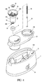
- a preferred embodiment of a humidifier in the present invention includes a body 1 having a switch 10, a water chamber 11 and a water level sensor 12, a water storing tank 2, and a cap 13 as main components combined together.
- the water level sensor 12 may be an infrared sensor shown in Figs. 5 and 6, a HALL effect digital switch or a near switch or any element having the same function, normally deposited in the water chamber 11 of the body 1.
- the cap 13 has an insert hole 130 formed in one side for receiving the lower portion of the water tank 2.
- the water storing tank 2 is a bellows-type tank 20, as shown in Fig. 3, or a common tank such as made of hard plastic, combined with a bottom base 21, which has a conical wall 22 closely fitting a bottom portion of the water tank 2 to prevent water from leaking out, a female threads portion 220 extending down from the conical wall 22 to engage with a male threads portion of the bottom portion of the water tank 2, and an outer cylindrical portion 221 under the conical wall 22 and having the same outer diameter as the inner diameter of the insert hole 130 of the cap 13 so that the bottom base 21 together with the water tank 2 may quickly assembled with or disassembled from the cap 13 and the body 1.
- the conical wall 22 has a water hole 23 in its bottom and a stopper 24 for closing the water hole 23 in case of stopping water to fall in the body 1.
- a connect rod 25 is provided, and a coil spring 26 fitting around the connect rod 25, and the upper end of the connect rod 25 screws with the stopper 24 by means of a nut.
- An inner cylindrical member 3 is vertically provided in the bottom base 21, located under the water hole 23 and extending down to protrude out of the bottom of the bottom base 21, having plural connect annular walls 30 formed in an upper end and connected to an annular wall of the water hole 23.
- the plural connect annular walls 30 have plural water gaps 231 for water to fall through into the water chamber 11 of the body 1.
- a small cylinder 31 is provided in the center of the connect wall 30 for the connect rod to pass through, having an annular spring recess 310 for a receiving a spring 26 to be compressed or resiliently push back the small cylinder 31.
- the inner cylindrical member 3 has plural grooves 32 formed in a bottom and a hook member 330 formed on an outer bottom end of each divided wall 33 of the cylindrical member 3.
- Each divided wall 33 has elasticity to expand or shrink back by means of the plural grooves 32.
- the lower end of the connect rod 25 is pushed up by the bottom base 120 of the water level sensor 12, forcing up the stopper 24 to open the water hole 23, permitting the water in the water tank 2 to flow into the water chamber 11 of the body 1 or to permit the water tank 2 communicate with the body 1.
- the annular float 4 fits around the inner cylindrical member 3 as shown in Figs. 7 and 8, the float 4 moves up and down together with the water level in the water chamber 11, raising up and down accordingly the inner cylindrical member 3 to decide function of the water level sensor 12 to turn or off the humidifier.
- the purpose of positioning the float 4 at the bottom of the bottom base 21 and near the water chamber 11 of the body 1 is to acquire the best water level condition in the water chamber 11 in the body 1, improving the disadvantage of the conventional humidifier having a float deposited in the water tank.
- the float 4 even if the humidifier should fall down to lie laterally, malfunction of the water level sensor may not happen to keep safe the humidifier and a user.
Landscapes
- Engineering & Computer Science (AREA)
- Chemical & Material Sciences (AREA)
- Combustion & Propulsion (AREA)
- Mechanical Engineering (AREA)
- General Engineering & Computer Science (AREA)
- Air Humidification (AREA)
- Two-Way Televisions, Distribution Of Moving Picture Or The Like (AREA)
- Air Conditioning Control Device (AREA)
Priority Applications (3)
| Application Number | Priority Date | Filing Date | Title |
|---|---|---|---|
| DE60122679T DE60122679T2 (de) | 2001-05-15 | 2001-05-15 | Befeuchter |
| EP01111762A EP1260772B1 (fr) | 2001-05-15 | 2001-05-15 | Humidificateur |
| AT01111762T ATE338252T1 (de) | 2001-05-15 | 2001-05-15 | Befeuchter |
Applications Claiming Priority (1)
| Application Number | Priority Date | Filing Date | Title |
|---|---|---|---|
| EP01111762A EP1260772B1 (fr) | 2001-05-15 | 2001-05-15 | Humidificateur |
Publications (2)
| Publication Number | Publication Date |
|---|---|
| EP1260772A1 true EP1260772A1 (fr) | 2002-11-27 |
| EP1260772B1 EP1260772B1 (fr) | 2006-08-30 |
Family
ID=8177438
Family Applications (1)
| Application Number | Title | Priority Date | Filing Date |
|---|---|---|---|
| EP01111762A Expired - Lifetime EP1260772B1 (fr) | 2001-05-15 | 2001-05-15 | Humidificateur |
Country Status (3)
| Country | Link |
|---|---|
| EP (1) | EP1260772B1 (fr) |
| AT (1) | ATE338252T1 (fr) |
| DE (1) | DE60122679T2 (fr) |
Cited By (11)
| Publication number | Priority date | Publication date | Assignee | Title |
|---|---|---|---|---|
| CN101354173B (zh) * | 2008-09-01 | 2010-04-07 | 乐国兴 | 一种加湿器 |
| EP1941213A4 (fr) * | 2005-10-24 | 2011-03-23 | Lg Electronics Inc | Deshumidificateur |
| WO2011129541A3 (fr) * | 2010-04-12 | 2012-01-26 | Ha Ilho | Humidificateur dans lequel de l'eau est amené à partir de son côté supérieur |
| CN109114724A (zh) * | 2018-10-31 | 2019-01-01 | 安徽江航爱唯科环境科技有限公司 | 一种上加水加湿器的水位控制装置 |
| CN109341048A (zh) * | 2018-11-13 | 2019-02-15 | 奥克斯空调股份有限公司 | 一种排水装置及空调器 |
| KR20200014400A (ko) * | 2015-04-16 | 2020-02-10 | 삼성전자주식회사 | 가습기 및 가전기기 |
| US10634372B2 (en) * | 2016-06-13 | 2020-04-28 | Condair Group Ag | Dual-stage humidifier methods and systems |
| CN113719921A (zh) * | 2020-05-26 | 2021-11-30 | 青岛海尔空调器有限总公司 | 除湿机及其控制方法 |
| US11262090B2 (en) | 2018-01-19 | 2022-03-01 | Dri-Steem Corporation | Humidifier with automatic drain interval determination |
| US11421899B2 (en) | 2018-01-19 | 2022-08-23 | Dri-Steem Corporation | Condensing, ultra-low NOx gas-fired humidifier |
| EP4253851A1 (fr) * | 2022-03-31 | 2023-10-04 | Beijing Xiaomi Mobile Software Co., Ltd. | Humidificateur |
Families Citing this family (1)
| Publication number | Priority date | Publication date | Assignee | Title |
|---|---|---|---|---|
| KR20240095785A (ko) * | 2022-12-19 | 2024-06-26 | 엘지전자 주식회사 | 가습기 |
Citations (5)
| Publication number | Priority date | Publication date | Assignee | Title |
|---|---|---|---|---|
| US4031171A (en) * | 1974-12-25 | 1977-06-21 | Mikuni Kogyo Kabushiki Kaisha | Ultrasonic air humidifying apparatus |
| US4746466A (en) * | 1986-03-03 | 1988-05-24 | Tdk Corporation | Ultrasonic atomizing apparatus |
| US5133044A (en) * | 1990-08-01 | 1992-07-21 | Duracraft Corporation | Portable humidifier |
| JPH05113236A (ja) * | 1991-10-22 | 1993-05-07 | Matsushita Seiko Co Ltd | 加湿機 |
| JP2000266370A (ja) * | 1999-03-15 | 2000-09-29 | Aiwa Co Ltd | 加湿装置 |
-
2001
- 2001-05-15 AT AT01111762T patent/ATE338252T1/de not_active IP Right Cessation
- 2001-05-15 DE DE60122679T patent/DE60122679T2/de not_active Expired - Fee Related
- 2001-05-15 EP EP01111762A patent/EP1260772B1/fr not_active Expired - Lifetime
Patent Citations (5)
| Publication number | Priority date | Publication date | Assignee | Title |
|---|---|---|---|---|
| US4031171A (en) * | 1974-12-25 | 1977-06-21 | Mikuni Kogyo Kabushiki Kaisha | Ultrasonic air humidifying apparatus |
| US4746466A (en) * | 1986-03-03 | 1988-05-24 | Tdk Corporation | Ultrasonic atomizing apparatus |
| US5133044A (en) * | 1990-08-01 | 1992-07-21 | Duracraft Corporation | Portable humidifier |
| JPH05113236A (ja) * | 1991-10-22 | 1993-05-07 | Matsushita Seiko Co Ltd | 加湿機 |
| JP2000266370A (ja) * | 1999-03-15 | 2000-09-29 | Aiwa Co Ltd | 加湿装置 |
Non-Patent Citations (2)
| Title |
|---|
| PATENT ABSTRACTS OF JAPAN vol. 017, no. 479 (M - 1471) 31 August 1993 (1993-08-31) * |
| PATENT ABSTRACTS OF JAPAN vol. 2000, no. 12 3 January 2001 (2001-01-03) * |
Cited By (17)
| Publication number | Priority date | Publication date | Assignee | Title |
|---|---|---|---|---|
| EP1941213A4 (fr) * | 2005-10-24 | 2011-03-23 | Lg Electronics Inc | Deshumidificateur |
| CN101354173B (zh) * | 2008-09-01 | 2010-04-07 | 乐国兴 | 一种加湿器 |
| WO2011129541A3 (fr) * | 2010-04-12 | 2012-01-26 | Ha Ilho | Humidificateur dans lequel de l'eau est amené à partir de son côté supérieur |
| KR20200014400A (ko) * | 2015-04-16 | 2020-02-10 | 삼성전자주식회사 | 가습기 및 가전기기 |
| US10634372B2 (en) * | 2016-06-13 | 2020-04-28 | Condair Group Ag | Dual-stage humidifier methods and systems |
| US11940178B2 (en) | 2018-01-19 | 2024-03-26 | Dri-Steem Corporation | Condensing, ultra-low NOx gas-fired humidifier |
| US11262090B2 (en) | 2018-01-19 | 2022-03-01 | Dri-Steem Corporation | Humidifier with automatic drain interval determination |
| US11421899B2 (en) | 2018-01-19 | 2022-08-23 | Dri-Steem Corporation | Condensing, ultra-low NOx gas-fired humidifier |
| CN109114724B (zh) * | 2018-10-31 | 2023-08-22 | 安徽江航爱唯科环境科技有限公司 | 一种上加水加湿器的水位控制装置 |
| CN109114724A (zh) * | 2018-10-31 | 2019-01-01 | 安徽江航爱唯科环境科技有限公司 | 一种上加水加湿器的水位控制装置 |
| CN109341048A (zh) * | 2018-11-13 | 2019-02-15 | 奥克斯空调股份有限公司 | 一种排水装置及空调器 |
| CN109341048B (zh) * | 2018-11-13 | 2024-02-23 | 奥克斯空调股份有限公司 | 一种空调器 |
| CN113719921B (zh) * | 2020-05-26 | 2023-03-24 | 青岛海尔空调器有限总公司 | 除湿机及其控制方法 |
| CN113719921A (zh) * | 2020-05-26 | 2021-11-30 | 青岛海尔空调器有限总公司 | 除湿机及其控制方法 |
| EP4253851A1 (fr) * | 2022-03-31 | 2023-10-04 | Beijing Xiaomi Mobile Software Co., Ltd. | Humidificateur |
| US20230314017A1 (en) * | 2022-03-31 | 2023-10-05 | Beijing Xiaomi Mobile Software Co., Ltd. | Humidifier |
| US12422153B2 (en) * | 2022-03-31 | 2025-09-23 | Beijing Xiaomi Mobile Software Co., Ltd. | Humidifier |
Also Published As
| Publication number | Publication date |
|---|---|
| EP1260772B1 (fr) | 2006-08-30 |
| ATE338252T1 (de) | 2006-09-15 |
| DE60122679T2 (de) | 2007-10-04 |
| DE60122679D1 (de) | 2006-10-12 |
Similar Documents
| Publication | Publication Date | Title |
|---|---|---|
| EP1260772B1 (fr) | Humidificateur | |
| US6259860B1 (en) | Humidifier | |
| US6135427A (en) | Humidifier | |
| US7182321B2 (en) | Safety device for a humidifier | |
| US10661044B2 (en) | Humidification chamber having suspension type float | |
| US5880423A (en) | Water level sensor | |
| KR200438801Y1 (ko) | 안전스위치 기능을 갖는 수위감지장치 | |
| JP5966254B2 (ja) | 電気ポット | |
| JP6407851B2 (ja) | 電気ポット | |
| CN112354705A (zh) | 一种具有侧感应区和底感应区的感应花洒 | |
| JP5967184B2 (ja) | 電気ポット | |
| JPH0616563Y2 (ja) | ポットの蒸気通路 | |
| JPH033921U (fr) | ||
| JPS5850728B2 (ja) | スチ−ムオ−ブン | |
| JPH0315636U (fr) | ||
| JP2016064259A (ja) | 電気ポット | |
| JPH049940Y2 (fr) | ||
| JP2008125585A (ja) | 芳香剤収納器 | |
| JP2000257929A (ja) | 加湿器 | |
| JP6041021B2 (ja) | 電気ポット | |
| JP6041019B2 (ja) | 電気ポット | |
| JP2000257928A (ja) | 加湿器 | |
| JP6041020B2 (ja) | 電気ポット | |
| KR200332143Y1 (ko) | 보온병 뚜껑 | |
| JP2000257924A (ja) | 加湿器 |
Legal Events
| Date | Code | Title | Description |
|---|---|---|---|
| PUAI | Public reference made under article 153(3) epc to a published international application that has entered the european phase |
Free format text: ORIGINAL CODE: 0009012 |
|
| AK | Designated contracting states |
Kind code of ref document: A1 Designated state(s): AT BE CH CY DE DK ES FI FR GB GR IE IT LI LU MC NL PT SE TR |
|
| AX | Request for extension of the european patent |
Free format text: AL;LT;LV;MK;RO;SI |
|
| 17P | Request for examination filed |
Effective date: 20030116 |
|
| AKX | Designation fees paid |
Designated state(s): AT BE CH CY DE DK ES FI FR GB GR IE IT LI LU MC NL PT SE TR |
|
| GRAP | Despatch of communication of intention to grant a patent |
Free format text: ORIGINAL CODE: EPIDOSNIGR1 |
|
| GRAS | Grant fee paid |
Free format text: ORIGINAL CODE: EPIDOSNIGR3 |
|
| GRAA | (expected) grant |
Free format text: ORIGINAL CODE: 0009210 |
|
| AK | Designated contracting states |
Kind code of ref document: B1 Designated state(s): AT BE CH CY DE DK ES FI FR GB GR IE IT LI LU MC NL PT SE TR |
|
| PG25 | Lapsed in a contracting state [announced via postgrant information from national office to epo] |
Ref country code: CH Free format text: LAPSE BECAUSE OF FAILURE TO SUBMIT A TRANSLATION OF THE DESCRIPTION OR TO PAY THE FEE WITHIN THE PRESCRIBED TIME-LIMIT Effective date: 20060830 Ref country code: IT Free format text: LAPSE BECAUSE OF FAILURE TO SUBMIT A TRANSLATION OF THE DESCRIPTION OR TO PAY THE FEE WITHIN THE PRESCRIBED TIME-LIMIT;WARNING: LAPSES OF ITALIAN PATENTS WITH EFFECTIVE DATE BEFORE 2007 MAY HAVE OCCURRED AT ANY TIME BEFORE 2007. THE CORRECT EFFECTIVE DATE MAY BE DIFFERENT FROM THE ONE RECORDED. Effective date: 20060830 Ref country code: NL Free format text: LAPSE BECAUSE OF FAILURE TO SUBMIT A TRANSLATION OF THE DESCRIPTION OR TO PAY THE FEE WITHIN THE PRESCRIBED TIME-LIMIT Effective date: 20060830 Ref country code: FI Free format text: LAPSE BECAUSE OF FAILURE TO SUBMIT A TRANSLATION OF THE DESCRIPTION OR TO PAY THE FEE WITHIN THE PRESCRIBED TIME-LIMIT Effective date: 20060830 Ref country code: LI Free format text: LAPSE BECAUSE OF FAILURE TO SUBMIT A TRANSLATION OF THE DESCRIPTION OR TO PAY THE FEE WITHIN THE PRESCRIBED TIME-LIMIT Effective date: 20060830 Ref country code: BE Free format text: LAPSE BECAUSE OF FAILURE TO SUBMIT A TRANSLATION OF THE DESCRIPTION OR TO PAY THE FEE WITHIN THE PRESCRIBED TIME-LIMIT Effective date: 20060830 Ref country code: AT Free format text: LAPSE BECAUSE OF FAILURE TO SUBMIT A TRANSLATION OF THE DESCRIPTION OR TO PAY THE FEE WITHIN THE PRESCRIBED TIME-LIMIT Effective date: 20060830 |
|
| REG | Reference to a national code |
Ref country code: GB Ref legal event code: FG4D |
|
| REG | Reference to a national code |
Ref country code: CH Ref legal event code: EP |
|
| REG | Reference to a national code |
Ref country code: IE Ref legal event code: FG4D |
|
| REF | Corresponds to: |
Ref document number: 60122679 Country of ref document: DE Date of ref document: 20061012 Kind code of ref document: P |
|
| PG25 | Lapsed in a contracting state [announced via postgrant information from national office to epo] |
Ref country code: SE Free format text: LAPSE BECAUSE OF FAILURE TO SUBMIT A TRANSLATION OF THE DESCRIPTION OR TO PAY THE FEE WITHIN THE PRESCRIBED TIME-LIMIT Effective date: 20061130 Ref country code: DK Free format text: LAPSE BECAUSE OF FAILURE TO SUBMIT A TRANSLATION OF THE DESCRIPTION OR TO PAY THE FEE WITHIN THE PRESCRIBED TIME-LIMIT Effective date: 20061130 |
|
| PG25 | Lapsed in a contracting state [announced via postgrant information from national office to epo] |
Ref country code: ES Free format text: LAPSE BECAUSE OF FAILURE TO SUBMIT A TRANSLATION OF THE DESCRIPTION OR TO PAY THE FEE WITHIN THE PRESCRIBED TIME-LIMIT Effective date: 20061211 |
|
| PG25 | Lapsed in a contracting state [announced via postgrant information from national office to epo] |
Ref country code: PT Free format text: LAPSE BECAUSE OF FAILURE TO SUBMIT A TRANSLATION OF THE DESCRIPTION OR TO PAY THE FEE WITHIN THE PRESCRIBED TIME-LIMIT Effective date: 20070212 |
|
| REG | Reference to a national code |
Ref country code: CH Ref legal event code: PL |
|
| NLV1 | Nl: lapsed or annulled due to failure to fulfill the requirements of art. 29p and 29m of the patents act | ||
| ET | Fr: translation filed | ||
| PGFP | Annual fee paid to national office [announced via postgrant information from national office to epo] |
Ref country code: DE Payment date: 20070529 Year of fee payment: 7 |
|
| PLBE | No opposition filed within time limit |
Free format text: ORIGINAL CODE: 0009261 |
|
| STAA | Information on the status of an ep patent application or granted ep patent |
Free format text: STATUS: NO OPPOSITION FILED WITHIN TIME LIMIT |
|
| 26N | No opposition filed |
Effective date: 20070531 |
|
| GBPC | Gb: european patent ceased through non-payment of renewal fee |
Effective date: 20070515 |
|
| PG25 | Lapsed in a contracting state [announced via postgrant information from national office to epo] |
Ref country code: MC Free format text: LAPSE BECAUSE OF NON-PAYMENT OF DUE FEES Effective date: 20070531 |
|
| PG25 | Lapsed in a contracting state [announced via postgrant information from national office to epo] |
Ref country code: GR Free format text: LAPSE BECAUSE OF FAILURE TO SUBMIT A TRANSLATION OF THE DESCRIPTION OR TO PAY THE FEE WITHIN THE PRESCRIBED TIME-LIMIT Effective date: 20061201 |
|
| PG25 | Lapsed in a contracting state [announced via postgrant information from national office to epo] |
Ref country code: IE Free format text: LAPSE BECAUSE OF NON-PAYMENT OF DUE FEES Effective date: 20070515 Ref country code: GB Free format text: LAPSE BECAUSE OF NON-PAYMENT OF DUE FEES Effective date: 20070515 |
|
| PG25 | Lapsed in a contracting state [announced via postgrant information from national office to epo] |
Ref country code: DE Free format text: LAPSE BECAUSE OF NON-PAYMENT OF DUE FEES Effective date: 20081202 |
|
| PG25 | Lapsed in a contracting state [announced via postgrant information from national office to epo] |
Ref country code: CY Free format text: LAPSE BECAUSE OF FAILURE TO SUBMIT A TRANSLATION OF THE DESCRIPTION OR TO PAY THE FEE WITHIN THE PRESCRIBED TIME-LIMIT Effective date: 20060830 Ref country code: LU Free format text: LAPSE BECAUSE OF NON-PAYMENT OF DUE FEES Effective date: 20070515 |
|
| PG25 | Lapsed in a contracting state [announced via postgrant information from national office to epo] |
Ref country code: TR Free format text: LAPSE BECAUSE OF FAILURE TO SUBMIT A TRANSLATION OF THE DESCRIPTION OR TO PAY THE FEE WITHIN THE PRESCRIBED TIME-LIMIT Effective date: 20060830 |
|
| REG | Reference to a national code |
Ref country code: FR Ref legal event code: ST Effective date: 20100129 |
|
| PG25 | Lapsed in a contracting state [announced via postgrant information from national office to epo] |
Ref country code: FR Free format text: LAPSE BECAUSE OF NON-PAYMENT OF DUE FEES Effective date: 20090602 |
|
| PGFP | Annual fee paid to national office [announced via postgrant information from national office to epo] |
Ref country code: FR Payment date: 20080520 Year of fee payment: 8 |