EP1260797A2 - Débitmètre - Google Patents
Débitmètre Download PDFInfo
- Publication number
- EP1260797A2 EP1260797A2 EP02252922A EP02252922A EP1260797A2 EP 1260797 A2 EP1260797 A2 EP 1260797A2 EP 02252922 A EP02252922 A EP 02252922A EP 02252922 A EP02252922 A EP 02252922A EP 1260797 A2 EP1260797 A2 EP 1260797A2
- Authority
- EP
- European Patent Office
- Prior art keywords
- flow
- fluid
- charging
- coil
- flow meter
- Prior art date
- Legal status (The legal status is an assumption and is not a legal conclusion. Google has not performed a legal analysis and makes no representation as to the accuracy of the status listed.)
- Withdrawn
Links
- 239000012530 fluid Substances 0.000 claims abstract description 162
- 238000005259 measurement Methods 0.000 claims abstract description 84
- 230000004907 flux Effects 0.000 claims description 29
- 238000011144 upstream manufacturing Methods 0.000 claims description 11
- 238000000034 method Methods 0.000 claims description 7
- 238000002955 isolation Methods 0.000 claims description 4
- 230000004044 response Effects 0.000 claims description 4
- 238000012544 monitoring process Methods 0.000 claims description 3
- 238000006073 displacement reaction Methods 0.000 abstract description 10
- 230000007423 decrease Effects 0.000 description 10
- 238000007599 discharging Methods 0.000 description 10
- 102100039216 Dolichyl-diphosphooligosaccharide-protein glycosyltransferase subunit 2 Human genes 0.000 description 9
- 101000670093 Homo sapiens Dolichyl-diphosphooligosaccharide-protein glycosyltransferase subunit 2 Proteins 0.000 description 9
- 230000001186 cumulative effect Effects 0.000 description 6
- 230000000694 effects Effects 0.000 description 6
- 101100479019 Encephalitozoon intestinalis SWP2 gene Proteins 0.000 description 5
- 101100519877 Schizosaccharomyces pombe (strain 972 / ATCC 24843) phf2 gene Proteins 0.000 description 5
- 230000003247 decreasing effect Effects 0.000 description 4
- XLYOFNOQVPJJNP-UHFFFAOYSA-N water Substances O XLYOFNOQVPJJNP-UHFFFAOYSA-N 0.000 description 4
- 230000001419 dependent effect Effects 0.000 description 3
- 230000005284 excitation Effects 0.000 description 3
- 230000008859 change Effects 0.000 description 2
- 238000011161 development Methods 0.000 description 2
- 230000018109 developmental process Effects 0.000 description 2
- 238000010586 diagram Methods 0.000 description 2
- 238000009434 installation Methods 0.000 description 2
- 239000000696 magnetic material Substances 0.000 description 2
- 239000000463 material Substances 0.000 description 2
- 230000021715 photosynthesis, light harvesting Effects 0.000 description 2
- 229920003023 plastic Polymers 0.000 description 2
- 239000004033 plastic Substances 0.000 description 2
- 230000035945 sensitivity Effects 0.000 description 2
- 238000000926 separation method Methods 0.000 description 2
- 238000004381 surface treatment Methods 0.000 description 2
- 229910001369 Brass Inorganic materials 0.000 description 1
- RYGMFSIKBFXOCR-UHFFFAOYSA-N Copper Chemical compound [Cu] RYGMFSIKBFXOCR-UHFFFAOYSA-N 0.000 description 1
- 230000032683 aging Effects 0.000 description 1
- 230000003466 anti-cipated effect Effects 0.000 description 1
- 230000015572 biosynthetic process Effects 0.000 description 1
- 239000010951 brass Substances 0.000 description 1
- 239000004020 conductor Substances 0.000 description 1
- 230000008602 contraction Effects 0.000 description 1
- 239000010949 copper Substances 0.000 description 1
- 229910052802 copper Inorganic materials 0.000 description 1
- 230000008878 coupling Effects 0.000 description 1
- 238000010168 coupling process Methods 0.000 description 1
- 238000005859 coupling reaction Methods 0.000 description 1
- 125000004122 cyclic group Chemical group 0.000 description 1
- 238000009792 diffusion process Methods 0.000 description 1
- 230000007246 mechanism Effects 0.000 description 1
- 239000002245 particle Substances 0.000 description 1
- 238000002161 passivation Methods 0.000 description 1
- 230000002028 premature Effects 0.000 description 1
- 230000008569 process Effects 0.000 description 1
- 238000012545 processing Methods 0.000 description 1
- 230000003252 repetitive effect Effects 0.000 description 1
- 229910001220 stainless steel Inorganic materials 0.000 description 1
- 239000010935 stainless steel Substances 0.000 description 1
- 230000001052 transient effect Effects 0.000 description 1
Images






Classifications
-
- G—PHYSICS
- G01—MEASURING; TESTING
- G01F—MEASURING VOLUME, VOLUME FLOW, MASS FLOW OR LIQUID LEVEL; METERING BY VOLUME
- G01F5/00—Measuring a proportion of the volume flow
-
- G—PHYSICS
- G01—MEASURING; TESTING
- G01F—MEASURING VOLUME, VOLUME FLOW, MASS FLOW OR LIQUID LEVEL; METERING BY VOLUME
- G01F1/00—Measuring the volume flow or mass flow of fluid or fluent solid material wherein the fluid passes through a meter in a continuous flow
- G01F1/56—Measuring the volume flow or mass flow of fluid or fluent solid material wherein the fluid passes through a meter in a continuous flow by using electric or magnetic effects
- G01F1/58—Measuring the volume flow or mass flow of fluid or fluent solid material wherein the fluid passes through a meter in a continuous flow by using electric or magnetic effects by electromagnetic flowmeters
- G01F1/588—Measuring the volume flow or mass flow of fluid or fluent solid material wherein the fluid passes through a meter in a continuous flow by using electric or magnetic effects by electromagnetic flowmeters combined constructions of electrodes, coils or magnetic circuits, accessories therefor
-
- G—PHYSICS
- G01—MEASURING; TESTING
- G01F—MEASURING VOLUME, VOLUME FLOW, MASS FLOW OR LIQUID LEVEL; METERING BY VOLUME
- G01F1/00—Measuring the volume flow or mass flow of fluid or fluent solid material wherein the fluid passes through a meter in a continuous flow
- G01F1/56—Measuring the volume flow or mass flow of fluid or fluent solid material wherein the fluid passes through a meter in a continuous flow by using electric or magnetic effects
- G01F1/58—Measuring the volume flow or mass flow of fluid or fluent solid material wherein the fluid passes through a meter in a continuous flow by using electric or magnetic effects by electromagnetic flowmeters
- G01F1/60—Circuits therefor
-
- G—PHYSICS
- G01—MEASURING; TESTING
- G01F—MEASURING VOLUME, VOLUME FLOW, MASS FLOW OR LIQUID LEVEL; METERING BY VOLUME
- G01F15/00—Details of, or accessories for, apparatus of groups G01F1/00 - G01F13/00 insofar as such details or appliances are not adapted to particular types of such apparatus
- G01F15/18—Supports or connecting means for meters
- G01F15/185—Connecting means, e.g. bypass conduits
Definitions
- the present invention relates to a fluid flow meter, in particular to a water meter primarily, but not exclusively, designed for domestic applications.
- a known positive displacement flow meter comprises an eccentric piston oscillating within a chamber which has inlet and outlet ports.
- the inlet port receives a flow of fluid from the mains supply, the flow being returned to the mains supply via the outlet.
- Such meters operate on the volumetric principle that for each revolution of the piston a fixed amount of water is measured.
- the piston moves circumferentially about the axis of the chamber and sweeps a known volume as fluid passes from the inlet to the outlet port.
- a magnetic or other external connecting element is rotationally driven by the piston through a drive coupling in the form of a peg or post on the piston engaging a radial arm of the connecting element which rotates about the chamber axis to drive an external register.
- Displacement flow meters may be interposed between flanged upstream and downstream portions of a supply pipe or other fluid line so that the flow of fluid in the pipe flows directly through the meter.
- displacement flow meters may be connected to a manifold connector which diverts the flow of fluid from the supply pipe to the meter, and returns the flow of fluid to the supply pipe.
- manifold type meters are easier to install and replace than the "through-flow" type meters because only a single joint with the manifold connector needs to be broken.
- displacement flow meters The lifetime of displacement flow meters is short, due to wear of the moving parts of the meter. Any wear tends to cause the accuracy of the measurement of the amount of fluid passing through the meter to deteriorate. As a result, German law requires displacement flow meters to be replaced 6 years after installation.
- the present invention provides a flow meter comprising first fluid conveying means for receiving a flow of fluid from a manifold connector disposed in a mains supply pipe through an inlet, and delivering the flow to a flow measurement duct, means for generating a magnetic field across the duct, means for deriving a flow measurement from a voltage induced by said magnetic field across the fluid, or a quantity indicative of said voltage, and second fluid conveying means for conveying fluid from the measurement duct back to the manifold connector through an outlet adjacent said inlet.
- the lifetime of the flow meter is anticipated to be in excess of 20 years, compared to the lifetime of 6 years of displacement flow meters, thus providing a substantial increase to the lifetime of a manifold type flow meter.
- the first conveying means is configured to deliver the flow substantially cavitation-free to the flow measurement duct.
- the first fluid conveying means reverses the direction of flow of the fluid. Configuring the first conveying means to avoid cavitation of the measuring duct then is particularly advantageous.
- the flow meter comprises an annular inlet chamber for receiving the flow of fluid from the manifold connector and supplying the flow of fluid to the first conveying means.
- the second conveying means may pass through the inlet chamber to return fluid to the manifold connector.
- This can provide a compact structure for receiving a flow of fluid from, and returning the flow of fluid to, the manifold connector.
- the second conveying means is preferably divergent in order to reduce the flow velocity of the fluid and improve hydrodynamic consistency of the fluid as it leaves the meter. This can prevent fluid from "rebounding" back into the manifold connector from the wall of the mains supply as it is returned to the mains supply.
- the annular inlet chamber comprises guide means for guiding the flow of fluid towards said first conveying means so as to reduce turbulence in the inlet chamber.
- the guide means comprises a fin projecting from the internal wall of said chamber opposite said first conveying means.
- the internal wall of the inlet chamber is preferably chamfered to guide the flow of fluid towards said first conveying means.
- the meter comprises means for mounting the meter on the manifold connector so that the flow axis of the flow measurement duct is substantially orthogonal to the longitudinal extent of the mains supply.
- the first conveying means comprises a substantially U-shaped tube. This can enable the flow meter to be built to substantially the same size as a displacement manifold type flow meter.
- the measurement duct may comprise an upstream convergent Venturi portion for channelling the flow of fluid into the flow measurement duct, the convergent portion being of length sufficient to suppress cavitation occurring in the first fluid conveying means, preferably to allow flow to develop without cavitation.
- the variation in the angular velocity of the fluid flowing around the bend of the tube can, for high flow rates, create localised pressure differences in the fluid, which can result, in severe cases, in cavitation in the fluid.
- the length of the upstream convergent portion is chosen to provide the longest possible "run-in" for the fluid from the bend into the measurement portion. This can enable the flow of fluid to be properly developed before reaching the measurement portion.
- the convergence increases the mean velocity of the fluid flow through the measurement portion, thus increasing the strength of the electromagnetically induced signal.
- the second fluid conveying means preferably comprises a divergent Venturi portion for receiving the flow of fluid from said flow measurement duct, said upstream convergent portion being substantially longer than said downstream divergent portion.
- the upstream convergent portion is preferably approximately three times longer than said downstream divergent portion.
- the flow measurement duct is preferably of substantially rectangular cross-section.
- the present invention provides a flow meter for mounting on a manifold connector in a supply pipe, the meter comprising an annular inlet portion for receiving a flow of fluid from the manifold connector, a conduit including a U-tube connecting the inlet portion to an elongate convergent Venturi section, a flow measurement duct, means for inferentially measuring a flow of fluid through the measurement duct, and a divergent Venturi section for receiving the flow of fluid from the measurement duct and returning it to the manifold connector via an outlet portion disposed within the annular inlet portion.
- the conduit is preferably of substantially constant flow area.
- the outlet portion is preferably divergent in the direction of flow.
- the inferential measuring means preferably comprises means for generating a magnetic field across the measuring duct and means for deriving a flow measurement from a voltage induced by said magnetic field across the fluid, or a quantity indicative of said voltage.
- the meter comprises a lower housing configured for mounting on the manifold connector by rotation relative thereto and an upper housing connected to the lower housing.
- the upper housing can house a battery for supplying power to the meter and drive circuitry for driving the generating means, and the means for deriving a flow measurement from the voltage induced by said magnetic field in the fluid.
- the lower housing can house the measurement duct and generating means.
- the manifold connector is internally threaded to engage an external thread of the lower housing to connect the meter to the mains supply.
- a snap-fit connection is typically provided to connect the upper and lower housing of the meter, the end of the upper housing being slid over an O-ring located on the lower housing to provide a water tight seal between the housings.
- the upper housing is gripped and twisted to unscrew the meter from the manifold connector. This can result in excessive torque being applied to the snap-fit connection between the upper and lower housings of the meter by the installer, which can in turn result in damage to, or even breaking of, the casing of the meter,
- the upper housing is slidably removable from the lower housing and connected thereto by structure capable of transmitting torque to the lower housing for rotating the lower housing.
- the casing comprises one or more dovetails provided on one of the upper and lower housing for slidably locating into corresponding recesses provided in the other of the upper and lower housings.
- the generating means comprises at least one coil and charging means for charging the coil from an energy supply to generate said magnetic field.
- a voltage is induced in the fluid subjected to the magnetic flux in a direction orthogonal to both the direction of fluid flow and the magnetic flux.
- Fluctuation in the flux density B can be caused by a fluctuation in the voltage V cc supplied to the coil from the meter's power supply, typically a battery.
- V cc the voltage supplied by the battery
- a voltage regulator is typically provided between the battery and the coil so as to ensure that a steady voltage is supplied to the coil.
- use of such a voltage regulator for example, a DC/DC converter, can reduce the energy efficiency of the meter by as much as 30-40%. Therefore, it is an object of at least the preferred embodiment of the invention to provide a flow meter which does not require a voltage regulator to ensure that the magnitude of the flux density B remains constant.
- the flow meter comprises charging control means for adjusting the charging of the coil in response to variations in an unregulated energy supply so as to maintain the magnitude of magnetic flux density across the duct substantially level during measurement of the flow.
- the present invention also provides a flow meter comprising a flow measurement duct, generating means for generating a magnetic field across the duct, and means for deriving a flow measurement from a voltage induced in fluid flowing in the duct, or a quantity indicative thereof, wherein the generating means comprises at least one coil, charging means for charging the coil from an unregulated energy supply to generate said magnetic field, and charging control means for adjusting the charging of the coil in response to variations in the energy supply so as to maintain the magnitude of magnetic flux density across the duct substantially constant during measurement of the flow. Accordingly, the use of voltage regulators can be avoided, thus further increasing the energy efficiency of the meter.
- the charging control means is arranged to adjust the charging of the coil from the energy supply so as to control the size of the hysteresis loop, that is, the variation of flux density with magnetic field, generated as the coil is charged. This can provide a convenient way to compensate for any variation in the magnetic field due, for example, an increase in the current in the coil.
- the charging control means is arranged to control the size of the hysteresis loop by controlling the magnitude of the maximum current in the coil during charging thereof.
- the charging control means is arranged to measure the time taken, during charging, for the current in the coil to reach a predetermined level, and to control the duration of the remainder of the charging time in order to control the magnitude of the maximum current in the coil.
- the charging control means is arranged to control said charging means so that, during an initial charging period, the coil is continuously charged from the energy supply and, during a subsequent measuring period, the coil is intermittently charged from the energy supply, so as to maintain a substantially constant mean flux density.
- This can avoid the use of voltage boosters to provide a transient increase in the energy supplied to the coil in order to establish rapidly the magnetic field.
- the present invention also provides a flow meter comprising a flow measurement duct, generating means for generating a magnetic field across the duct, and means for deriving a flow measurement from a voltage induced in fluid flowing in the duct, or a quantity indicative thereof, wherein the generating means comprises at least one coil, charging means for charging the coil from an energy supply to generate said magnetic field, and charging control means for controlling said charging means so that, during an initial charging period, the coil is continually charged from the energy supply and, during a subsequent measuring period, the coil is intermittently charged from the energy supply.
- the current in the coil reaches a maximum at the end of said initial period, said charging control means being arranged to control the duration of said initial period so as to control the size of the hysteresis loop generated as the coil is charged.
- the charging means comprises a switching circuit having a plurality of switches, said charging control means being arranged to control the sequence of operating said switches so as to control the duration of said initial period.
- the flow meter preferably comprises a battery as the unregulated energy supply for charging said coil.
- the charging control means is arranged to control said charging means to commutate the current supplied to the coil to generate the magnetic field in alternating directions.
- the charging control means is arranged to control said charging means to commutate the current supplied to the coil to generate the magnetic field in alternating directions.
- the charging means comprises a switching circuit having a plurality of switches, said charging control means being arranged to control the sequence of operating said switches so as to suppress voltage fluctuation across the coil during commutation.
- the applicants have observed that voltage fluctuation across the coil during commutation can be suppressed by controlling the sequence of operating, that is. opening and closing, the switches of the switching circuit.
- the present invention provides a flow meter comprising a flow measurement duct, generating means for generating a magnetic field across the duct, and means for deriving a flow measurement from a voltage induced in fluid flowing in the duct, wherein the generating means comprises at least one coil, charging means for charging the coil from an energy supply to generate said magnetic field, and charging control means for controlling said charging means, wherein said charging means comprises a switching circuit having a plurality of switches and said charging control means is arranged to control the sequence of operating said switches so as to suppress voltage fluctuation across the coil during commutation.
- the charging control means is arranged to open said first switch before closing said second switch.
- the timing sequence is "off first then on”.
- said charging control means is arranged to open first the last of those switches to have been closed.
- the timing sequence is "first on last off'.
- the charging control means is arranged to control the sequence of operating said switches such that the coil is sequentially charged by the current supplied thereto from the energy supply and discharged in isolation from the energy supply.
- Such a cyclic operation of the coil can enable a pseudo-steady current to be developed in the coil to maintain the flux density B at a constant level during measurement of the flow rate through the duct.
- I m is the "aiming" current, given by the ratio of the supply voltage V cc and the resistance R of the coil circuit
- I 0 is the initial current at the start of the charge/discharge period
- ⁇ is time constant of the coil circuit, given by the ratio of the inductance L and resistance R of the coil circuit.
- the coil is discharged through a loop comprising a plurality of closed switches of the switching circuit. This minimises the voltage across the coil, thus reducing ( I 0 - I m ) to a minimum and consequently minimising the rate of current discharge.
- the present invention also provides a flow meter comprising a flow measurement duct, generating means for generating a magnetic field across the duct, and means for deriving a flow measurement from a voltage induced in fluid flowing in the duct, or a quantity indicative thereof, wherein the generating means comprises at least one coil, charging means for charging the coil from an energy supply to generate said magnetic field, and charging control means for controlling said charging means, wherein said charging means comprises a switching circuit having a plurality of switches and said charging control means is arranged to control the sequence of operating said switches so the coil is sequentially charged from the energy supply and discharged in isolation from the energy supply through a loop comprising a plurality of closed switches.
- the switching circuit is an H-bridge circuit, one of said switches being located on each arm of the circuit.
- Another aspect of the present invention provides a method of detecting the presence of a leak of fluid from a mains supply, comprising the steps of:
- the method preferably comprises the steps of:
- a flow meter 10 comprises a plastics meter body 12 having an annular inlet chamber 14 for receiving a flow of fluid diverted to the meter from a mains supply, or supply pipe, by a manifold connector (not shown).
- the inlet chamber 14 has an outlet 16 for supplying the flow of fluid to a first conveying pipe 18 for conveying the flow of fluid to a measurement duct 20.
- the flow of fluid is returned to the manifold connector, and so back to the mains supply by a second conveying pipe 22 passing through the inlet chamber 14, so that the inlet to the meter is adjacent the outlet from the meter to provide a compact structure of the meter.
- the second conveying pipe is divergent from the measurement duct to the mains supply in order to reduce the velocity of the fluid as it leaves the meter and also provide better hydrodynamic consistency. This can prevent fluid from "rebounding" back into the manifold connector from the wall of the mains supply as it is returned to the mains supply.
- the inlet chamber 14 is designed to guide the flow of fluid received from the manifold connector to the outlet 16 in order to minimise turbulence in the inlet chamber before the fluid flow is supplied to the first conveying pipe 18. Any turbulent mixing of the fluid in the inlet chamber can reduce the momentum of the fluid in the meter, dissipating energy from the fluid in the form of heat and increasing the pressure drop across the meter.
- the inlet chamber 14 includes a fin 24 projecting from the internal wall of the inlet chamber 14 opposite the outlet 16. The fin 24 acts to reduce the tendency of fluid to "spin" in the inlet chamber by effectively splitting the flow of fluid into two as it hits the fin 24. This has the effect of guiding the flow of fluid towards the outlet 16.
- the internal wall of the inlet chamber 14 is chamfered, as shown at 26, to assist in guiding the flow of fluid to the outlet 16.
- the first conveying pipe 18 includes a substantially U-shaped tube 28 for reversing the flow of fluid to convey it to the measurement duct 20.
- the tube 28 enables the flow meter 10 to be built to substantially the same size as a displacement flow meter whilst enabling the distance that the fluid flows between the inlet chamber 14 and the measurement duct 20 to be maximised to maximise the development of the profile of the flow of fluid as it enters the measurement duct 20.
- the measurement duct 20 comprises a tapered non-magnetic, non-conducting, non-permeable tube, for example, of a plastics material preferably treated to render it impervious to water seepage under pressure.
- the measurement duct is shaped to aid flow profile development therethrough for a range of fluid flow rates in the duct 20 with minimum variation in the pressure of the fluid leaving the measurement duct at the outlet to the second conveying pipe 22.
- the duct 20 is in the form of a Venturi tube, having a circular cross-section at its inlet and outlet ends, blended by contraction (converging) and diffusion (diverging) portions 30,32 to an intermediate portion 34 of rectangular cross-section through which the rate of flow of fluid through the meter is determined.
- the rectangular shape of the portion 34 also promotes a flow regime which is relatively uniform across its width (apart from boundary layer effects) for a wide range of flow rates leading to a more nearly linear calibration characteristic for the meter.
- the variation in the angular velocity of the fluid flowing around the bend of the tube 28 can, for high flow velocities of up to 15m/s, create localised pressure differences in the fluid, which can result, in severe cases, in cavitation of the fluid.
- the upstream convergent portion 30 is longer, preferably approximately three times longer, than the downstream divergent portion 32 so as to provide the longest possible "run-in" for the fluid from the bend into the intermediate portion 34. This can enable, even in the most extreme cases, the profile of the flow of fluid to be properly developed before reaching the intermediate portion 34 where the flow rate is measured.
- a pair of electrode housings 36 are provided in the measurement duct 20, one electrode 38 being disposed in each electrode housing 36 so that the electrodes are disposed orthogonally across the direction of flow of fluid in the measurement duct 20.
- the electrodes may be formed from any suitable non-contaminating conducting material, such as stainless steel, plated copper or brass.
- the electrodes 38 may have rectangular, elliptical or a circular cross-section.
- the material from which the electrodes are formed may be subjected to cleansing and surface treatments, such as passivation, to permit the formation of a uniform oxide layer on the contact surface of the electrodes exposed to the fluid flowing in the measurement duct 20. Such surface treatments can reduce the susceptibility of the electrodes to electrochemical effects such as polarisation, and ensure a consistent electrode impedance from meter to meter.
- the manifold connector is internally threaded to engage an external thread (not shown) on the body 12 to connect the meter to the manifold.
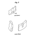
- the meter 10 further includes an upper portion or cap (not shown) releasably secured to the body 12 over an O-ring 40 located in a recess at the upper end of the body 12.
- the cap houses a battery for supplying power to the meter, a coil driver circuit for driving a coil for generating a magnetic field across the intermediate portion of the measurement duct 20, signal processing circuitry and a display.
- one or more dovetails 42 are provided on the cap for slidably locating corresponding recesses in the body 12 as the cap is connected to the body. This enables torque to be transmitted from the cap to the lower housing for rotating the lower housing without damaging the cap.
- the magnetic circuit for generating the magnetic field across the intermediate portion of the measurement duct 20 will now be described.
- the magnetic circuit is similar to that described in our International patent application no. WO 98/49528, the contents of which are incorporated herein by reference, and therefore will not be explained in detail here.
- the magnetic circuit comprises a pair of magnetic pole pieces having an enlarged face portion for directing magnetic flux across the measurement duct, specifically by channelling flux on to a plane perpendicular to the direction of flow of fluid in the measurement duct 20.
- the magnetic field is generated by energising the magnetic circuit by one or more excitation coils connected to the pole pieces and driven by a coil drive circuit. This is described in more detail below
- the coil drive circuit is adapted to supply current with alternating polarity cyclically to the coils, thus creating a bi-directional (alternating) magnetic field orthogonal to the fluid flow in the measurement duct 24.
- alternating field any ionisation and electrochemical influences acting on the electrodes can be prevented; with a unidirectional magnetic field in the measurement duct the voltage induced between the electrodes also is unidirectional.
- particles in the fluid are polarised and tend to adhere to the surface of the electrodes, which can lead over time to partial or complete blockage of the duct, creating measurement errors and premature meter failure.
- FIG. 4 illustrates a circuit diagram for the flow meter.
- the circuit includes at least one excitation coil 50 having a core made from soft magnetic material, and, for each coil, a coil driver circuit 52, a switching circuit 54 in the form of an H-bridge circuit having a switch on each arm thereof, and resistor 56.
- the switching circuit 54 receives a voltage V cc supplied from the battery and supplies excitation current to the coil 50.
- the driver circuit 52 controls the operational sequence (opening/closing) of the switches of the switching circuit 54.
- Each cycle is typically of duration 20ms and comprises an initial charging phase, during which the coil 50 is charged continuously from the supply voltage V cc , and a subsequent measuring phase during which the coil is repeatedly charged and then allowed to discharge on a 8kHz time base.
- switches SWP1 and SWN2 are closed and switches SWP2 and SWN1 are open to enable the coil 50 to be charged by the supply voltage V cc .
- this enables the current in the coil to increase rapidly to a magnitude I max in order to establish rapidly the magnetic field across the measurement duct 20.
- the duration of time period t ini is not fixed, but is determined by measuring the time t pre taken for the current in the coil to reach a predetermined current during the initial charging period, from which the further time required for the current to reach I max can be determined.
- the measuring phase commences and a time base 58, illustrated in Figure 7, of frequency 8kHz commences for the duration of the measuring phase.
- switch SWN1 is opened and SWP1 is closed to increase the current in the coil.
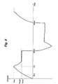
- switch SWP1 is immediately opened and switch SWN1 is immediately closed, as illustrated in Figure 5(b), causing the coil 50 to discharge, the current I in the coil decreasing, as shown in Figure 6, from I max .
- SWN1 is opened and SWP1 is closed, and a new charge-discharge cycle begins.
- the measuring phase settles into a period of repetitive charging and discharging of the coil 50 to maintain the desired mean current level I mean for the remainder of the 20ms cycle.
- the current is commutated and the cycle repeated.
- the current I in the coil is monitored by the drive circuit 52 by comparing the voltage across the resistor 56 with a reference voltage. This can enable both the duration of the initial charging period, t ini , during which the current in the coil increases to I max , to be controlled (by controlling the timing of the opening and closing of the switches to end this initial charging period), and the duration of t c , during which the current in the coil increases to I target , and thus the mark/space ratio t c / t d , to be controlled (by controlling the timing of the operation of the switches).
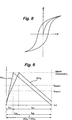
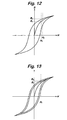
- a curve of B versus H can be plotted.
- a curve is illustrated in Figure 8.
- the maximum value of H reached during the charging process determines the size of the hysteresis loop. Accordingly, the size of the hysteresis loop is determined by I max .
- the coil operates at a flux density B determined solely by the strength of the magnetic field H, or coil current I which generates the magnetic field.
- the operating section of the hysteresis loop can be approximated with a linear relation as given below.
- B a H+ b where a and b are constants for a straight line.
- the duration t c of the charging cycle will increase from t c1 to t c2 , as illustrated in figure 9, as it will take longer for the current I in the coil to reach I target .
- the charge rate of the coil 50 will decrease with decreasing V cc .
- V cc An effect of a decrease in V cc is to decrease the rate of increase of the current I at the start of the 20ms cycle.
- the current I max at the end of a given time period t ini will decrease.
- decreasing the magnitude of I max decreases the size of the hysteresis loop, which, for a constant mean current I mean in the coil during time period T, or constant H, will decrease the magnitude of the flux density B from B 2 to B 1 .
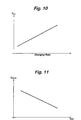
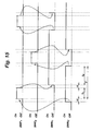
- any fluctuation of the flux density B due to fluctuation of the mean current in the coil can be compensated by adjusting the duration of t ini to control I max and thus the size of the hysteresis loop, as illustrated in figure 14; with V cc1 ⁇ V cc2 ⁇ V cc3 , I mean1 > I mean2 > I mean3 , and so by selecting I max1 ⁇ I max2 ⁇ I max3 , L 1 ⁇ L 2 ⁇ L 3 so as to keep the flux density B at a constant level.
- the flux density can be maintained constant for a varying supply voltage by controlling t ini in such a manner that variations in B due to changes in I mean and the size of the hysteresis loop cancel each other out.
- One method of controlling t ini is to measure the time, t pre , taken for the current in the coil to reach a predetermined current, for example, I target , during the initial charging period, as shown in Figure 6, from which the further time required for the current to reach I max can be determined from the known I-t relationship already mentioned.
- switch SWN2 is closed, switches SWP2 and SWN1 are open and switch SWP1 is sequentially closed and opened to enable the coil 50 to be charged by the supply voltage V cc .
- switches SWP1 and SWP2 are open and switches SWN1 and SWN2 are closed to enable the coil 50 to be discharged through a closed loop formed by the coil 50 and switches SWN1, SWN2.
- the sequence of opening and closing the switches of the H-bridge circuit 54 is such that:
- switch SWP1 is switched off before switch SWN1 is switched on.
- switch SWN2 is switched off before switch SWP2 is switched on.
- the meter 10 is capable of implementing different priorities of fluid supply, for example, priorities A, B, C, and D, related to the expected demand.
- a day is notionally divided into 48 half hour periods, each period being assigned a respective priority.
- the periods between 12.00am and 4.00am, when fluid consumption is expected to be low may be assigned a low priority A
- the periods between 7.00am and 10.00am when consumption is expected to be high, may be assigned a high priority D.
- the meter 10 includes a totaliser for each period to store, for each priority, the total amount of fluid used by each consumer during the time periods allocated that priority.
- the number of priorities can vary both up and down depending on the complexity with which fluid consumption is to be monitored. However, the number of totalisers can only increase so as to preserve readings from any totalisers no longer in use.
- the stored amounts of fluid respectively used by a group of individually metered consumers are periodically monitored to determine for each priority the cumulative amount of fluid used from the mains supply by all of those consumers during the time periods allocated that priority. This enables, for each priority, the cumulative amount to be compared to the actual amount of fluid drawn by the group (as measured by a single upstream meter) from the mains supply during the time periods allocated that priority to detect the presence of a leak of fluid from the mains supply.
- the presence of a leak of fluid from the mains supply can be detected when there is a consistent difference between the cumulative amount and the actual amount, and is confirmed when the difference between said cumulative amount and said actual amount is approximately the same for each priority.
- This can provide an accurate method of monitoring for the presence of leaks, as a difference between the actual amount and the cumulative amount for periods allocated a low priority, that is, priority A, can provide a clear indication of the presence of a leak from the supply.
- priorities A may be accorded a first, lower tariff, whilst priorities B, C and D may be accorded a second higher tariff.
- a manifold-type flow meter comprises means for supplying a flow of fluid diverted from a mains supply to first fluid conveying means for conveying a streamlined flow of fluid to a flow measurement duct, means for generating a magnetic field across the duct, means for deriving a flow measurement from the voltage induced by said magnetic field in the fluid, and second fluid conveying means for conveying fluid from the measurement duct back to the mains supply.
- first fluid conveying means for conveying a streamlined flow of fluid to a flow measurement duct
- means for generating a magnetic field across the duct means for deriving a flow measurement from the voltage induced by said magnetic field in the fluid
- second fluid conveying means for conveying fluid from the measurement duct back to the mains supply.
Landscapes
- Physics & Mathematics (AREA)
- Fluid Mechanics (AREA)
- General Physics & Mathematics (AREA)
- Electromagnetism (AREA)
- Measuring Volume Flow (AREA)
Applications Claiming Priority (2)
| Application Number | Priority Date | Filing Date | Title |
|---|---|---|---|
| GB0110175A GB2378761B (en) | 2001-04-25 | 2001-04-25 | Flow meter |
| GB0110175 | 2001-04-25 |
Publications (2)
| Publication Number | Publication Date |
|---|---|
| EP1260797A2 true EP1260797A2 (fr) | 2002-11-27 |
| EP1260797A3 EP1260797A3 (fr) | 2003-08-06 |
Family
ID=9913458
Family Applications (1)
| Application Number | Title | Priority Date | Filing Date |
|---|---|---|---|
| EP02252922A Withdrawn EP1260797A3 (fr) | 2001-04-25 | 2002-04-25 | Débitmètre |
Country Status (2)
| Country | Link |
|---|---|
| EP (1) | EP1260797A3 (fr) |
| GB (1) | GB2378761B (fr) |
Cited By (9)
| Publication number | Priority date | Publication date | Assignee | Title |
|---|---|---|---|---|
| EP1394514A1 (fr) * | 2002-08-28 | 2004-03-03 | ABB PATENT GmbH | Méthode pour commander un débitmètre magnéto-inductif |
| EP2440887A4 (fr) * | 2009-06-12 | 2018-02-28 | Sensus USA Inc. | Débitmètre magnétique et son procédé de fabrication |
| WO2018095644A1 (fr) * | 2016-11-22 | 2018-05-31 | Endress+Hauser Flowtec Ag | Procédé de fonctionnement d'un appareil de mesure d'écoulement magnéto-inductif ainsi qu'appareil de mesure magnéto-inductif |
| WO2021045930A1 (fr) * | 2019-09-05 | 2021-03-11 | Micro Motion, Inc. | Débitmètre magnétique ayant un générateur de courant bidirectionnel programmable |
| US11181404B2 (en) | 2019-09-05 | 2021-11-23 | Micro Motion, Inc. | Magnetic flowmeter with a current sampling circuit sampling coil current pulses at a sampling frequency |
| WO2021239352A1 (fr) * | 2020-05-29 | 2021-12-02 | Endress+Hauser Flowtec Ag | Dispositif de mesure de flux magnéto-inductif |
| US11204268B2 (en) | 2019-09-05 | 2021-12-21 | Micro Motion, Inc. | Magnetic flowmeter having a programmable bi-directional current generator |
| US11204267B2 (en) | 2019-09-05 | 2021-12-21 | Micro Motion, Inc. | Continuously adaptive digital coil driver for magnetic flowmeter |
| US11333537B2 (en) | 2019-09-05 | 2022-05-17 | Micro Motion, Inc. | Load leveling boost supply for magnetic flowmeter |
Families Citing this family (2)
| Publication number | Priority date | Publication date | Assignee | Title |
|---|---|---|---|---|
| JP6481430B2 (ja) * | 2015-03-11 | 2019-03-13 | 横河電機株式会社 | 電磁流量計 |
| CN114623034A (zh) * | 2020-12-14 | 2022-06-14 | 宜善电机工业有限公司 | 同轴水流启动器的加大力矩导流结构 |
Citations (2)
| Publication number | Priority date | Publication date | Assignee | Title |
|---|---|---|---|---|
| DE3509776A1 (de) * | 1985-03-19 | 1986-10-02 | Bopp & Reuther Gmbh, 6800 Mannheim | Verbindung zum anschliessen eines hauswasserzaehlers an ein unter putz liegendes t-stueck |
| WO2001009441A1 (fr) * | 1999-08-03 | 2001-02-08 | Oswald Peter John Meli | Connexion pour compteur d'eau |
Family Cites Families (12)
| Publication number | Priority date | Publication date | Assignee | Title |
|---|---|---|---|---|
| US4434667A (en) * | 1981-10-26 | 1984-03-06 | The United States Of America As Represented By The United States Department Of Energy | Permanent magnet flowmeter having improved output terminal means |
| JPS6128820A (ja) * | 1984-07-19 | 1986-02-08 | Hitachi Ltd | 電磁流量計 |
| US4768385A (en) * | 1986-08-13 | 1988-09-06 | Micro Motion, Inc. | Parallel path Coriolis mass flow meter |
| GB8802869D0 (en) * | 1988-02-09 | 1988-03-09 | Glynwed Tubes & Fittings | Improvements in/relating to valves |
| GB8827418D0 (en) * | 1988-11-24 | 1988-12-29 | Evans Gerald J | Adjustable meter manifold support plate |
| US5394339A (en) * | 1992-03-30 | 1995-02-28 | Paul-Munroe Hydraulics Inc. | Apparatus for analyzing oil well production fluid |
| JP2935944B2 (ja) * | 1993-04-13 | 1999-08-16 | 株式会社オーバル | 超音波流量計ユニット |
| JPH06341872A (ja) * | 1993-06-03 | 1994-12-13 | Hitachi Ltd | 電磁流量計検出器の測定管 |
| GB2310383A (en) * | 1993-10-11 | 1997-08-27 | Evans Gerald J | Meter and manifold assembly with particle entrapment recess |
| US5728945A (en) * | 1997-01-21 | 1998-03-17 | Elsag International N.V. | Electromagnetic flowmeter with internally placed, laminar flow supporting, grounding electrodes |
| GB2324606B (en) * | 1997-04-25 | 2002-01-16 | Kent Meters Ltd | Electromagnetic flowmeter |
| GB2328021B (en) * | 1997-08-01 | 2001-11-28 | Abb Kent Taylor Ltd | Electromagnetic flow sensor and assembly method |
-
2001
- 2001-04-25 GB GB0110175A patent/GB2378761B/en not_active Expired - Lifetime
-
2002
- 2002-04-25 EP EP02252922A patent/EP1260797A3/fr not_active Withdrawn
Patent Citations (2)
| Publication number | Priority date | Publication date | Assignee | Title |
|---|---|---|---|---|
| DE3509776A1 (de) * | 1985-03-19 | 1986-10-02 | Bopp & Reuther Gmbh, 6800 Mannheim | Verbindung zum anschliessen eines hauswasserzaehlers an ein unter putz liegendes t-stueck |
| WO2001009441A1 (fr) * | 1999-08-03 | 2001-02-08 | Oswald Peter John Meli | Connexion pour compteur d'eau |
Cited By (11)
| Publication number | Priority date | Publication date | Assignee | Title |
|---|---|---|---|---|
| EP1394514A1 (fr) * | 2002-08-28 | 2004-03-03 | ABB PATENT GmbH | Méthode pour commander un débitmètre magnéto-inductif |
| EP2440887A4 (fr) * | 2009-06-12 | 2018-02-28 | Sensus USA Inc. | Débitmètre magnétique et son procédé de fabrication |
| WO2018095644A1 (fr) * | 2016-11-22 | 2018-05-31 | Endress+Hauser Flowtec Ag | Procédé de fonctionnement d'un appareil de mesure d'écoulement magnéto-inductif ainsi qu'appareil de mesure magnéto-inductif |
| WO2021045930A1 (fr) * | 2019-09-05 | 2021-03-11 | Micro Motion, Inc. | Débitmètre magnétique ayant un générateur de courant bidirectionnel programmable |
| US11181404B2 (en) | 2019-09-05 | 2021-11-23 | Micro Motion, Inc. | Magnetic flowmeter with a current sampling circuit sampling coil current pulses at a sampling frequency |
| US11204268B2 (en) | 2019-09-05 | 2021-12-21 | Micro Motion, Inc. | Magnetic flowmeter having a programmable bi-directional current generator |
| US11204267B2 (en) | 2019-09-05 | 2021-12-21 | Micro Motion, Inc. | Continuously adaptive digital coil driver for magnetic flowmeter |
| US11333537B2 (en) | 2019-09-05 | 2022-05-17 | Micro Motion, Inc. | Load leveling boost supply for magnetic flowmeter |
| WO2021239352A1 (fr) * | 2020-05-29 | 2021-12-02 | Endress+Hauser Flowtec Ag | Dispositif de mesure de flux magnéto-inductif |
| US12332096B2 (en) | 2020-05-29 | 2025-06-17 | Endress+Hauser Flowtec Ag | Magneto-inductive flow measurement device |
| EP4556864A3 (fr) * | 2020-05-29 | 2025-08-13 | Endress+Hauser Flowtec AG | Débitmètre magnéto-inductif |
Also Published As
| Publication number | Publication date |
|---|---|
| GB2378761B (en) | 2005-11-30 |
| GB0110175D0 (en) | 2001-06-20 |
| GB2378761A (en) | 2003-02-19 |
| EP1260797A3 (fr) | 2003-08-06 |
Similar Documents
| Publication | Publication Date | Title |
|---|---|---|
| EP1260797A2 (fr) | Débitmètre | |
| JP4089769B2 (ja) | 磁気誘導形流量計 | |
| US9696188B2 (en) | Magnetic flowmeter with automatic adjustment based on sensed complex impedance | |
| US7213467B2 (en) | Flowmeter | |
| CN101720391B (zh) | 能量转换器、具有能量转换器的计数器、具有计数器的系统、将机械能转换成电能的方法以及计数方法 | |
| RU2413182C2 (ru) | Магнитоиндуктивный расходомер | |
| AU2002228232A1 (en) | Flowmeter | |
| CN102187182B (zh) | 用于节能地运行磁感应流量计的方法 | |
| KR100307267B1 (ko) | 유동액체의체적유량측정방법및액체계량기 | |
| KR101923954B1 (ko) | 소비전력이 절감된 배터리형 초음파식 수도미터 | |
| US7574924B1 (en) | Magnetic flow meter | |
| CN118882755A (zh) | 一种用于流量测量的涡轮流量计 | |
| LU101299B1 (en) | Volume flowmeter and method for determining a volumetric flow rate | |
| CZ20002941A3 (en) | Method for the magnetic-inductive measurement of fluid flow | |
| US5646354A (en) | Microwave thermal trace flowmeter | |
| RU2008102111A (ru) | Магнитно-индукционный расходомер (варианты) | |
| CN101263367A (zh) | 用于确定磁感应流量计的工作点的方法 | |
| US20080048142A1 (en) | Valve with Inherent Enhanced Turbulent Flow Metering Device and Flow Regulation | |
| JP2003057086A (ja) | 磁気誘導式流量計 | |
| GB2376529A (en) | Electromagnetic flowmeter | |
| RU2807438C1 (ru) | Суммирующий индукционный топливомер-расходомер | |
| SU1296845A1 (ru) | Расходомер жидкости и газа | |
| RU2807437C1 (ru) | Суммирующий индуктивный топливомер-расходомер | |
| RU2807439C1 (ru) | Суммирующий индукционный топливомер-расходомер | |
| KR102832520B1 (ko) | 자가발전 시스템을 갖는 전자식 유량계 |
Legal Events
| Date | Code | Title | Description |
|---|---|---|---|
| PUAI | Public reference made under article 153(3) epc to a published international application that has entered the european phase |
Free format text: ORIGINAL CODE: 0009012 |
|
| AK | Designated contracting states |
Kind code of ref document: A2 Designated state(s): AT BE CH CY DE DK ES FI FR GB GR IE IT LI LU MC NL PT SE TR |
|
| AX | Request for extension of the european patent |
Free format text: AL;LT;LV;MK;RO;SI |
|
| PUAL | Search report despatched |
Free format text: ORIGINAL CODE: 0009013 |
|
| AK | Designated contracting states |
Designated state(s): AT BE CH CY DE DK ES FI FR GB GR IE IT LI LU MC NL PT SE TR |
|
| AX | Request for extension of the european patent |
Extension state: AL LT LV MK RO SI |
|
| RIC1 | Information provided on ipc code assigned before grant |
Ipc: 7G 01F 1/58 A Ipc: 7G 01F 1/60 B |
|
| 17P | Request for examination filed |
Effective date: 20040206 |
|
| AKX | Designation fees paid |
Designated state(s): AT BE CH CY DE DK ES FI FR GB GR IE IT LI LU MC NL PT SE TR |
|
| 17Q | First examination report despatched |
Effective date: 20071219 |
|
| RAP1 | Party data changed (applicant data changed or rights of an application transferred) |
Owner name: ELSTER METERING LIMITED |
|
| RAP1 | Party data changed (applicant data changed or rights of an application transferred) |
Owner name: ELSTER METERING LIMITED |
|
| RAP1 | Party data changed (applicant data changed or rights of an application transferred) |
Owner name: ELSTER WATER METERING LIMITED |
|
| STAA | Information on the status of an ep patent application or granted ep patent |
Free format text: STATUS: THE APPLICATION IS DEEMED TO BE WITHDRAWN |
|
| 18D | Application deemed to be withdrawn |
Effective date: 20180119 |
|
| RIC1 | Information provided on ipc code assigned before grant |
Ipc: G01F 1/60 20060101ALI20030614BHEP Ipc: G01F 1/58 20060101AFI20020815BHEP |