EP1260894A2 - Verfahren zum Betrieb eines Antriebs und Vorrichtung - Google Patents
Verfahren zum Betrieb eines Antriebs und Vorrichtung Download PDFInfo
- Publication number
- EP1260894A2 EP1260894A2 EP02009137A EP02009137A EP1260894A2 EP 1260894 A2 EP1260894 A2 EP 1260894A2 EP 02009137 A EP02009137 A EP 02009137A EP 02009137 A EP02009137 A EP 02009137A EP 1260894 A2 EP1260894 A2 EP 1260894A2
- Authority
- EP
- European Patent Office
- Prior art keywords
- values
- value
- threshold values
- threshold
- volatile memory
- Prior art date
- Legal status (The legal status is an assumption and is not a legal conclusion. Google has not performed a legal analysis and makes no representation as to the accuracy of the status listed.)
- Granted
Links
- 238000000034 method Methods 0.000 title claims abstract description 18
- 230000015654 memory Effects 0.000 claims abstract description 26
- 238000009826 distribution Methods 0.000 claims description 16
- 230000006870 function Effects 0.000 claims description 6
- 238000013178 mathematical model Methods 0.000 claims description 2
- 239000011159 matrix material Substances 0.000 description 7
- 238000005259 measurement Methods 0.000 description 2
- 230000002123 temporal effect Effects 0.000 description 2
- 238000001514 detection method Methods 0.000 description 1
- 238000005315 distribution function Methods 0.000 description 1
- 238000011156 evaluation Methods 0.000 description 1
- 230000001788 irregular Effects 0.000 description 1
- 230000007774 longterm Effects 0.000 description 1
- 238000012544 monitoring process Methods 0.000 description 1
- 238000012545 processing Methods 0.000 description 1
- 230000000717 retained effect Effects 0.000 description 1
- 238000005070 sampling Methods 0.000 description 1
- 238000012549 training Methods 0.000 description 1
- 238000013024 troubleshooting Methods 0.000 description 1
Images


Classifications
-
- G—PHYSICS
- G05—CONTROLLING; REGULATING
- G05B—CONTROL OR REGULATING SYSTEMS IN GENERAL; FUNCTIONAL ELEMENTS OF SUCH SYSTEMS; MONITORING OR TESTING ARRANGEMENTS FOR SUCH SYSTEMS OR ELEMENTS
- G05B23/00—Testing or monitoring of control systems or parts thereof
- G05B23/02—Electric testing or monitoring
- G05B23/0205—Electric testing or monitoring by means of a monitoring system capable of detecting and responding to faults
- G05B23/0218—Electric testing or monitoring by means of a monitoring system capable of detecting and responding to faults characterised by the fault detection method dealing with either existing or incipient faults
- G05B23/0243—Electric testing or monitoring by means of a monitoring system capable of detecting and responding to faults characterised by the fault detection method dealing with either existing or incipient faults model based detection method, e.g. first-principles knowledge model
- G05B23/0254—Electric testing or monitoring by means of a monitoring system capable of detecting and responding to faults characterised by the fault detection method dealing with either existing or incipient faults model based detection method, e.g. first-principles knowledge model based on a quantitative model, e.g. mathematical relationships between inputs and outputs; functions: observer, Kalman filter, residual calculation, Neural Networks
-
- G—PHYSICS
- G05—CONTROLLING; REGULATING
- G05B—CONTROL OR REGULATING SYSTEMS IN GENERAL; FUNCTIONAL ELEMENTS OF SUCH SYSTEMS; MONITORING OR TESTING ARRANGEMENTS FOR SUCH SYSTEMS OR ELEMENTS
- G05B23/00—Testing or monitoring of control systems or parts thereof
- G05B23/02—Electric testing or monitoring
- G05B23/0205—Electric testing or monitoring by means of a monitoring system capable of detecting and responding to faults
- G05B23/0259—Electric testing or monitoring by means of a monitoring system capable of detecting and responding to faults characterized by the response to fault detection
- G05B23/0286—Modifications to the monitored process, e.g. stopping operation or adapting control
- G05B23/0289—Reconfiguration to prevent failure, e.g. usually as a reaction to incipient failure detection
Definitions
- the invention relates to a method for operating a drive and a device.
- drives are often used that include an electric motor Gearbox and an inverter include.
- an electric motor Gearbox and an inverter include.
- Nominal data to be observed when permanently exceeded especially when if the multiple of these nominal values is exceeded permanently, damage will occur can.
- the invention is therefore based on the object of a method for operating a drive further training, taking risks to people and machines in a cost-effective manner should be reducible.
- Another advantage is that the second values are saved and therefore from one correspondingly suitable device, in particular an electrically connectable computer, are processable. So there are also absolute and statistical data, in particular Probability distributions, determinable. Such data can also be used with for the drive known parameters, such as operating factors or the like, link and thus exceeding nominal values or permitted peak values or a Determine exceeding load limits.
- the storage has a volatile memory is executed, the values of which after longer time intervals, in particular 15 minutes, in a non-volatile memory can be written.
- the advantage here is that even after Power failure the data is retained. In the worst case, only the data go between the penultimate and the last time interval were lost.
- the time period is in each case less than one second.
- the advantage here is that the temporal resolution of the measurement data is very good.
- the time segments are 50 milliseconds each.
- the advantage here is that even short-term load peaks or fluctuations are noticeable.
- each measurement variable is one or more Thresholds are assigned, and that these thresholds are each graded are selected.
- the threshold values are graded constantly, so they form a consequence, the differences of directly successive threshold values of the sequence being the same.
- the time segments are of equal size. Is an advantage that a mere incrementation of the respective meter reading also the complete one contains temporal information. The storage space requirement can thus be reduced considerably. This is particularly advantageous when using non-volatile memories such as EEPROM, because they can only be written slowly and therefore large amounts of data only slowly would be storable, while small ones would be sufficiently quick.
- non-volatile memories such as EEPROM
- the second values are read, in particular from a system comprising a microprocessor such as a PC, central control computer, Laptop or the like, and a standardized frequency distribution is determined from it.
- a microprocessor such as a PC, central control computer, Laptop or the like
- a standardized frequency distribution is determined from it.
- the frequency distribution is two-dimensional or multidimensional, i.e. the frequency distribution is a function of two or more quantities is.
- the advantage here is that the analysis does not just depend on one Size like example torque but also depending on other sizes like speed can be determined as an example.
- the assessment of the burden is done with operational factors or operational factor functions that are practical and / or theoretically developed knowledge were determined.
- the frequency distribution is a two-dimensional one Function of torque and speed is.
- the advantage here is that in particular the load distribution can be represented in a simple and clear manner.
- further parameters such as statistical values in particular, can be easily calculated.
- the frequency distribution and service factor functions Calculate rated frequency distributions that exceed threshold values or Threshold curves Overloads and thus dangerous conditions can be identified.
- the frequency distribution can in particular also be used to calculate parameters which are: Convolution integrals are defined. Statistical moments can also be easily calculated.
- the frequency distribution is a discrete one Histogram determined. This makes the recorded second values particularly easy and record them discretely.
- the measured variables include a torque, a Speed, a current and / or a voltage.
- the advantage here is that the procedure can be used for different measured variables.
- torque and / or speed are turned off Measured values determined using a mathematical model.
- the advantage here is that not only values measured directly with sensors but also indirectly determined values are usable.
- Essential features of the invention in the device are that sensors for Determination of measured variables with which the converter is electrically connected, the converter comprises at least one volatile memory, from the converter and / or from another Device at least one non-volatile memory is included, and that the non-volatile Memory can be electrically connected to the volatile memory for data exchange, that the second values are permanent even for power failure of the device can be saved.
- the advantage here is that even in the event of a power failure, the essential amount the data is not lost.
- a counter is available.
- the advantage here is that in the device can be produced in a particularly simple and cost-effective manner, especially even without a microprocessor.
- the device is designed such that for each Threshold value is assigned to a counter, the count of the counters being one represents the second value, being in each time period during the operating time Counter reading is then increased, in particular by an increment, if the respective value for the respective measured variable is equal to or smaller than that assigned to the meter reading Threshold and this threshold is the smallest of all the thresholds that are greater than the value for the measured variable.
- FIG. 1 shows an exemplary time profile of the torque M of a drive schematically shown that drives a mechanical load.
- the associated speed curve n is also shown in FIG. 1.
- the time axis is marked with t.
- the drive includes an electric motor and a gearbox that carry the mechanical load drives.
- the load in the stationary case needs a constant one Torque.
- Such drives can be used in systems such as examples Transport devices for people and / or goods on assembly lines.
- electric motors are also included Brake and / or usable with angular or angular velocity sensors. About that single or multi-stage gearboxes can also be used.
- a converter is used to supply the electric motor.
- This includes sensors which can be used to determine other physical quantities. In particular is measured by the software of the signal electronics from values for current in a value for torque is determined at regular intervals. It uses the Software uses a mathematical motor model, which determines the specific value for torque also slight deviations from the true physical value of the torque can have, especially in the case of non-stationary, abrupt courses of the Torque.
- a value for speed can also be determined with the software, whereby this Value also slight deviations from the true physical value of the speed may have, especially at low speeds or the speed 0 rpm.
- the drive also includes one Angular or angular velocity sensor, the speed is even direct and therefore particularly easy to grasp.
- the speed is even direct and therefore particularly easy to grasp.
- other sensors such as torque sensors can be used, which then also provide a more direct and better value for torque.
- the value for torque and the value become after each time period ⁇ t detected for speed and compared with threshold values.
- To the thresholds are respective meter readings assigned at the beginning of the operating time of the converter when commissioning for the first time are set to zero.
- the counter reading associated with the respective threshold value increases when the value for Torque or speed is equal to or less than the threshold and Threshold is the smallest of all those thresholds that are greater than the value for Torque or speed. This increase is proportional to the duration of the time periods. In the case of regular, equally large time segments, the counter reading is therefore incremented.
- the time segments are irregular and of different sizes.
- the counter reading is thus increased by an amount increased, which is proportional to the respective length of the period concerned.
- the associated counter reading is also referred to as the second value.
- the threshold values have a even equidistant gradation.
- the first threshold is 10% of the Nominal value.
- the second threshold at 20% of the nominal value.
- the nth threshold lies then at n / 10 * 100% of the nominal value.
- Embodiment runs n from 1 to 15 each for torque and speed. Each A counter reading is assigned to the threshold value.
- each counter reading is a respective speed-torque combination assigned.
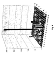
- the counter readings form a double-indexed, finite matrix and are shown in FIG. 3 shown as an example in two dimensions.
- the abscissa and ordinate are speed and Torque assigned.
- FIG. 3 An exemplary matrix of counter readings is shown in FIG. 3. That area of Meter readings with all sizes below the nominal values, i.e. 100%, are darker characterized.
- the matrix is used for further processing of the data by a computer Adding all counter readings determines the total number of time periods. By dividing all Matrix elements by this total number result from the matrix into a matrix discrete frequency distribution.
- This frequency distribution is then used to determine the degree of exposure.
- the matrix elements are multiplied by respective operating factors, whereby which are such that a critical number is exceeded by the respective Multiplication result indicates an impermissible load.
- such is inadmissible Load the drive switched off or its performance limited.
- the counter readings are stored in a first invention Embodiment in the converter itself.
- a particular advantage of using equally large time periods is that one Incrementation of the respective counter readings is sufficient and thus the invention Procedure is executable for an extremely large number of periods. It will even only an extremely small memory is required. This is illustrated in Figure 2.
- An exemplary one Memory for meter readings there only contains 4 bytes each. This results in a Sampling rate of 1 kHz, i.e. periods of 0.001 s, in the worst case a maximum evaluable operating time of 1193 hours, which is 49.7 days or about 0.1 years equivalent.
- finer and / or not Uniform equidistant gradations of the threshold values can be carried out.
- the Meter readings in larger time intervals, for example every 15 minutes, in one non-volatile memory such as EEPROM.
- one non-volatile memory such as EEPROM.
- the non-volatile memory is in an embodiment according to the invention in Converter installed. In another embodiment according to the invention it is mounted together with another electronic circuit in another housing, whereby it is connected to the converter via an electrical interface. to Evaluation can then be connected to a computer and the meter readings to this PC be transmitted. In other exemplary embodiments according to the invention, it is also Can be connected via a fieldbus or another bus. Alternatively, the dates are also in the non-volatile memory of another bus participant or the central computer transferable and evaluable there.
Landscapes
- Engineering & Computer Science (AREA)
- Physics & Mathematics (AREA)
- Automation & Control Theory (AREA)
- General Physics & Mathematics (AREA)
- Mathematical Physics (AREA)
- Chemical Kinetics & Catalysis (AREA)
- Artificial Intelligence (AREA)
- Evolutionary Computation (AREA)
- Chemical & Material Sciences (AREA)
- Control Of Electric Motors In General (AREA)
- Power Steering Mechanism (AREA)
- Vending Machines For Individual Products (AREA)
- Vehicle Body Suspensions (AREA)
- Arrangements For Transmission Of Measured Signals (AREA)
- Measuring Or Testing Involving Enzymes Or Micro-Organisms (AREA)
- Control Of Stepping Motors (AREA)
Abstract
- Werte für eine oder mehrere Messgrößen detektiert werden,
- die Werte mit Schwellenwerten verglichen werden,
- zweite Werte aus einem Speicher gelesen werden,
- abhängig vom Ergebnis des Vergleichens die zweiten Werte verändert werden und dann im Speicher gespeichert werden.
Description
- Werte für eine oder mehrere Messgrößen bestimmt und/oder detektiert werden,
- die Werte jeweils mit Schwellenwerten verglichen werden,
- zweite Werte aus einem Speicher gelesen werden,
- abhängig vom Ergebnis des Vergleichens die zweiten Werte verändert werden und dann im Speicher gespeichert werden.
- n
- Drehzahl
- M
- Drehmoment
- t
- Zeit
- Δt
- Zeitabschnitt
Claims (10)
- Verfahren zum Betrieb eines Antriebs,
dadurch gekennzeichnet, dass
jeweils nach einem ZeitabschnittWerte für eine oder mehrere Größen bestimmt und/oder detektiert werden,die Werte jeweils mit Schwellenwerten verglichen werden,zweite Werte aus einem Speicher gelesen werden,abhängig vom Ergebnis des Vergleichens die zweiten Werte verändert werden und dann im Speicher gespeichert werden. - Verfahren nach mindestens einem der vorangegangenen Ansprüche,
dadurch gekennzeichnet, dass
die Größen Messgrößen oder von einer Software aus mindestens einer Messgröße bestimmte Modellgrößen sind. - Verfahren nach mindestens einem der vorangegangenen Ansprüche,
dadurch gekennzeichnet, dass
das Speichern in einen flüchtigen Speicher ausgeführt wird, dessen Werte nach größeren Zeitabständen, insbesondere 15 Minuten, in einen nichtflüchtigen Speicher geschrieben werden
und/oder dass
der Zeitabschnitt jeweils kleiner als eine Sekunde ist
und/oder dass
die Zeitabschnitte jeweils 50 Millisekunden betragen. - Verfahren nach mindestens einem der vorangegangenen Ansprüche,
dadurch gekennzeichnet, dass
jeder Größe ein oder mehrere Schwellenwerte zugeordnet sind,
und dass diese Schwellenwerte jeweils gemäß einer Stufung gewählt sind
und/oder dass
die Stufung derart ist, dass die Schwellenwerte konstant gestuft sind, also eine Folge bilden, wobei die Differenzen direkt aufeinander folgender Schwellenwerte der Folge gleich sind
und/oder dass
die Stufung derart ist, dass die Schwellenwerte logarithmisch gestuft sind, also eine Folge bilden, wobei die Differenzen des Logarithmus direkt aufeinander folgender Schwellenwerte der Folge gleich sind. - Verfahren nach mindestens einem der vorangegangenen Ansprüche,
dadurch gekennzeichnet, dass
zu jedem zweiten Wert mindestens ein Schwellenwert gehört
und/oder dass
die Schwellenwerte jeweils entweder eine obere oder eine unter Schranke darstellen
und/oder dass
die Zeitabschnitte gleichgroß sind
und/oder dass
das Verändern der zweiten Werte ein Erhöhen ist
und/oder dass
das Erhöhen des zweiten Wertes proportional zum jeweiligen Zeitabschnitt ist
und/oder dass
die zweiten Werte gelesen werden, insbesondere von einem einen Mikroprozessor umfassenden System wie PC, zentraler Steuerungsrechner, Laptop oder dergleichen, und daraus ein Histogramm bestimmt wird. - Verfahren nach mindestens einem der vorangegangenen Ansprüche,
dadurch gekennzeichnet, dass
das Histogramm normiert wird
und/oder dass
das normierte Histogramm eine diskrete Häufigkeitsverteilung darstellt
und/oder dass
die zweiten Werte gelesen werden, insbesondere von einem einen Mikroprozessor umfassenden System wie PC, zentraler Steuerungsrechner, Laptop oder dergleichen, und daraus eine normierte kontinuierliche Häufigkeitsverteilung bestimmt wird
und/oder dass
die Häufigkeitsverteilung eine zwei- oder mehrdimensionale Funktion von zwei oder mehreren Größen ist. - Verfahren nach mindestens einem der vorangegangenen Ansprüche,
dadurch gekennzeichnet, dass
die Häufigkeitsverteilung eine zwei- oder mehrdimensionale Funktion von Drehmoment und Drehzahl ist
und/oder dass
die Schwellenwerte eine diskrete und/oder endliche Menge bilden. - Verfahren nach mindestens einem der vorangegangenen Ansprüche,
dadurch gekennzeichnet, dass
die Messgrößen ein Drehmoment, eine Drehzahl, einen Strom und/oder eine Spannung umfassen
und/oder dass
Drehmoment und/oder Drehzahl aus Messwerten mittels eines mathematischen Modells bestimmt werden. - Vorrichtung zur Durchführung des Verfahrens nach mindestens einem der vorangegangenen Ansprüche,
dadurch gekennzeichnet, dass
Sensoren zur Bestimmung von Messgrößen mit dem Umrichter elektrisch verbunden sind, der Umrichter mindestens einen flüchtigen Speicher umfasst,
vom Umrichter und/oder von einer weiteren Vorrichtung mindestens ein nichtflüchtiger Speicher umfasst ist,
und dass der nichtflüchtige Speicher mit dem flüchtigen Speicher derart zum Datenaustausch elektrisch verbindbar ist, dass die zweiten Werte auch nach Ausfall der Stromversorgung der Vorrichtung dauerhaft abgespeichert bleiben. - Vorrichtung nach mindestens einem der vorangegangenen Ansprüche,
dadurch gekennzeichnet, dass
mindestens ein Zähler vorhanden ist
und/oder dass
die Vorrichtung derart ausgeführt ist, dass zu jedem Schwellenwert ein Zähler zugeordnet ist, wobei der Zählerstand der Zähler jeweils einen zweiten Wert repräsentiert,
wobei in jedem Zeitabschnitt während der Betriebszeit ein Zählerstand dann erhöht wird,
wenn der jeweilige Wert für die jeweilige Messgröße gleich oder kleiner ist als der zum Zählerstand zugeordnete Schwellenwert und dieser Schwellenwert der kleinste all derjenigen Schwellenwerte ist, die größer sind als der Wert für die Messgröße
und/oder dass
wobei in jedem Zeitabschnitt während der Betriebszeit ein Zählerstand um ein Inkrement erhöht wird.
Applications Claiming Priority (2)
| Application Number | Priority Date | Filing Date | Title |
|---|---|---|---|
| DE10122759 | 2001-05-10 | ||
| DE10122759.0A DE10122759B4 (de) | 2001-05-10 | 2001-05-10 | Verfahren zum Betrieb eines Antriebs und Vorrichtung |
Publications (3)
| Publication Number | Publication Date |
|---|---|
| EP1260894A2 true EP1260894A2 (de) | 2002-11-27 |
| EP1260894A3 EP1260894A3 (de) | 2003-07-30 |
| EP1260894B1 EP1260894B1 (de) | 2005-11-09 |
Family
ID=7684310
Family Applications (1)
| Application Number | Title | Priority Date | Filing Date |
|---|---|---|---|
| EP02009137A Expired - Lifetime EP1260894B1 (de) | 2001-05-10 | 2002-04-24 | Verfahren zum Betrieb eines Antriebs und Vorrichtung |
Country Status (3)
| Country | Link |
|---|---|
| EP (1) | EP1260894B1 (de) |
| AT (1) | ATE309567T1 (de) |
| DE (2) | DE10122759B4 (de) |
Cited By (2)
| Publication number | Priority date | Publication date | Assignee | Title |
|---|---|---|---|---|
| EP1450265A1 (de) * | 2003-02-10 | 2004-08-25 | Omron Corporation | Umrichter |
| CN109310244A (zh) * | 2016-06-10 | 2019-02-05 | 德国福维克控股公司 | 用于掼奶油的自动控制功能 |
Families Citing this family (2)
| Publication number | Priority date | Publication date | Assignee | Title |
|---|---|---|---|---|
| DE102004030076A1 (de) * | 2004-06-22 | 2006-02-09 | Bosch Rexroth Aktiengesellschaft | Intelligenter Antrieb |
| DE102007044880A1 (de) * | 2007-09-20 | 2009-04-16 | Siemens Ag | Verfahren zum Betreiben eines Umrichtergerätes sowie Steuereinheit hierfür |
Family Cites Families (4)
| Publication number | Priority date | Publication date | Assignee | Title |
|---|---|---|---|---|
| GB2125578A (en) * | 1982-08-16 | 1984-03-07 | Nissan Motor | Self monitoring system |
| US5051918A (en) * | 1989-09-15 | 1991-09-24 | United Technologies Corporation | Gas turbine stall/surge identification and recovery |
| US5255208A (en) * | 1991-08-08 | 1993-10-19 | Aeg Westinghouse Transportation Systems, Inc. | On-line processor based diagnostic system |
| US5606311A (en) * | 1995-08-30 | 1997-02-25 | General Motors Corporation | Air filter diagnostic |
-
2001
- 2001-05-10 DE DE10122759.0A patent/DE10122759B4/de not_active Expired - Lifetime
-
2002
- 2002-04-24 EP EP02009137A patent/EP1260894B1/de not_active Expired - Lifetime
- 2002-04-24 AT AT02009137T patent/ATE309567T1/de not_active IP Right Cessation
- 2002-04-24 DE DE50204825T patent/DE50204825D1/de not_active Expired - Lifetime
Cited By (2)
| Publication number | Priority date | Publication date | Assignee | Title |
|---|---|---|---|---|
| EP1450265A1 (de) * | 2003-02-10 | 2004-08-25 | Omron Corporation | Umrichter |
| CN109310244A (zh) * | 2016-06-10 | 2019-02-05 | 德国福维克控股公司 | 用于掼奶油的自动控制功能 |
Also Published As
| Publication number | Publication date |
|---|---|
| DE10122759A1 (de) | 2002-12-05 |
| DE10122759B4 (de) | 2017-06-08 |
| DE50204825D1 (de) | 2005-12-15 |
| ATE309567T1 (de) | 2005-11-15 |
| EP1260894A3 (de) | 2003-07-30 |
| EP1260894B1 (de) | 2005-11-09 |
Similar Documents
| Publication | Publication Date | Title |
|---|---|---|
| EP0895010B1 (de) | Verfahren zum Ueberwachen des Zustands einer mechanischen Dichtung | |
| DE102018103232B4 (de) | Fehlerdiagnosesystem | |
| DE10004464A1 (de) | Achstemepraturüberwachung | |
| EP3841366B1 (de) | Verfahren und system zur unmittelbaren ermittlung einer theoretischen schädigung mindestens einer komponente einer vorrichtung | |
| DE102007022348A1 (de) | Einrichtung und Verfahren zur Störungsüberwachung | |
| EP1607192B1 (de) | Verfahren und System zur Verschleissabschätzung von Achsen eines Roboterarmes | |
| WO2004078543A2 (de) | Risikominimierung und wartungsoptimierung durch ermittlung von schädigungsanteilen aus betriebsdaten | |
| DE102019205833A1 (de) | Maschinengesundheitsüberwachung von drehenden Maschinenanlagen | |
| EP3625629B1 (de) | Vorrichtung und verfahren zur bestimmung des zustands einer spindel einer werkzeugmaschine | |
| EP1260894A2 (de) | Verfahren zum Betrieb eines Antriebs und Vorrichtung | |
| WO2018178196A1 (de) | Verfahren zur bestimmung einer schädigungsmassunsicherheit eines kraftfahrzeugs | |
| EP3786607A1 (de) | Verfahren zur schadensprognose an einer komponente eines wälzlagers | |
| DE102020204817B4 (de) | Verfahren zur automatisierten Demontage und Montage eines Fahrzeugrads an einem Radflansch und Vorrichtung hierfür | |
| DE102008063927B4 (de) | Verfahren zur Bestimmung von Lastkollektiven von hydrostatischen Maschinen sowie entsprechendes Steuergerät | |
| DE10138013A1 (de) | Einrichtung zur Überwachung eines Verdichterrades | |
| DE19923824C5 (de) | Verfahren und Vorrichtung zur Bestimmung von Belastungsdaten eines über einen Hydromotor angetriebenen Getriebes | |
| DE10156330A1 (de) | Verfahren zur Bestimmung eines Betriebssicherheitsfaktors S_B und Schnittstelle | |
| DE4006948A1 (de) | Verfahren und anordnung zum ueberwachen des verschleisses oder der ermuedung eines zyklisch belasteten bauteils | |
| DE102018003222A1 (de) | Verfahren zum Prüfen einer eine Mehrzahl drehbarer Komponenten aufweisenden Drehkomponentenanordnung | |
| DE102023207829A1 (de) | Verfahren und System zum Erkennen von Anomalien in einem Satz von Signalen | |
| DE102022102379A1 (de) | Verfahren zum Betreiben einer Anlage für eine Serienherstellung von Bauteilen, Computerprogramm und Datenträger | |
| DE102017108281B4 (de) | Brennkraftmaschine und Verfahren zum Überwachen der Brennkraftmaschine | |
| DE102023134460B3 (de) | Verfahren und Vorrichtung zum Ermitteln eines Diagnosestatus eines Türsystems | |
| DE102019001627A1 (de) | Verfahren zur Verschleißerkennung und prädiktiven Verschleißprognose von elektromechanischen Aktuatoren zur Betriebszeit einer Maschine mit Verbrennungsmotor | |
| EP4070067B1 (de) | Verfahren und vorrichtung zur ermittlung eines schädigungszustands von bauteilen |
Legal Events
| Date | Code | Title | Description |
|---|---|---|---|
| PUAI | Public reference made under article 153(3) epc to a published international application that has entered the european phase |
Free format text: ORIGINAL CODE: 0009012 |
|
| AK | Designated contracting states |
Kind code of ref document: A2 Designated state(s): AT BE CH CY DE DK ES FI FR GB GR IE IT LI LU MC NL PT SE TR |
|
| AX | Request for extension of the european patent |
Free format text: AL;LT;LV;MK;RO;SI |
|
| PUAL | Search report despatched |
Free format text: ORIGINAL CODE: 0009013 |
|
| RAP1 | Party data changed (applicant data changed or rights of an application transferred) |
Owner name: SEW-EURODRIVE GMBH & CO. KG |
|
| AK | Designated contracting states |
Designated state(s): AT BE CH CY DE DK ES FI FR GB GR IE IT LI LU MC NL PT SE TR |
|
| AX | Request for extension of the european patent |
Extension state: AL LT LV MK RO SI |
|
| 17P | Request for examination filed |
Effective date: 20040130 |
|
| AKX | Designation fees paid |
Designated state(s): AT BE CH CY DE DK ES FI FR GB GR IE IT LI LU MC NL PT SE TR |
|
| 17Q | First examination report despatched |
Effective date: 20041020 |
|
| GRAP | Despatch of communication of intention to grant a patent |
Free format text: ORIGINAL CODE: EPIDOSNIGR1 |
|
| GRAS | Grant fee paid |
Free format text: ORIGINAL CODE: EPIDOSNIGR3 |
|
| GRAA | (expected) grant |
Free format text: ORIGINAL CODE: 0009210 |
|
| AK | Designated contracting states |
Kind code of ref document: B1 Designated state(s): AT BE CH CY DE DK ES FI FR GB GR IE IT LI LU MC NL PT SE TR |
|
| PG25 | Lapsed in a contracting state [announced via postgrant information from national office to epo] |
Ref country code: IT Free format text: LAPSE BECAUSE OF FAILURE TO SUBMIT A TRANSLATION OF THE DESCRIPTION OR TO PAY THE FEE WITHIN THE PRESCRIBED TIME-LIMIT;WARNING: LAPSES OF ITALIAN PATENTS WITH EFFECTIVE DATE BEFORE 2007 MAY HAVE OCCURRED AT ANY TIME BEFORE 2007. THE CORRECT EFFECTIVE DATE MAY BE DIFFERENT FROM THE ONE RECORDED. Effective date: 20051109 Ref country code: NL Free format text: LAPSE BECAUSE OF FAILURE TO SUBMIT A TRANSLATION OF THE DESCRIPTION OR TO PAY THE FEE WITHIN THE PRESCRIBED TIME-LIMIT Effective date: 20051109 Ref country code: FI Free format text: LAPSE BECAUSE OF FAILURE TO SUBMIT A TRANSLATION OF THE DESCRIPTION OR TO PAY THE FEE WITHIN THE PRESCRIBED TIME-LIMIT Effective date: 20051109 Ref country code: IE Free format text: LAPSE BECAUSE OF FAILURE TO SUBMIT A TRANSLATION OF THE DESCRIPTION OR TO PAY THE FEE WITHIN THE PRESCRIBED TIME-LIMIT Effective date: 20051109 |
|
| REG | Reference to a national code |
Ref country code: GB Ref legal event code: FG4D Free format text: NOT ENGLISH |
|
| REG | Reference to a national code |
Ref country code: CH Ref legal event code: EP |
|
| REG | Reference to a national code |
Ref country code: IE Ref legal event code: FG4D Free format text: LANGUAGE OF EP DOCUMENT: GERMAN |
|
| REF | Corresponds to: |
Ref document number: 50204825 Country of ref document: DE Date of ref document: 20051215 Kind code of ref document: P |
|
| GBT | Gb: translation of ep patent filed (gb section 77(6)(a)/1977) |
Effective date: 20060107 |
|
| PG25 | Lapsed in a contracting state [announced via postgrant information from national office to epo] |
Ref country code: SE Free format text: LAPSE BECAUSE OF FAILURE TO SUBMIT A TRANSLATION OF THE DESCRIPTION OR TO PAY THE FEE WITHIN THE PRESCRIBED TIME-LIMIT Effective date: 20060209 Ref country code: GR Free format text: LAPSE BECAUSE OF FAILURE TO SUBMIT A TRANSLATION OF THE DESCRIPTION OR TO PAY THE FEE WITHIN THE PRESCRIBED TIME-LIMIT Effective date: 20060209 Ref country code: DK Free format text: LAPSE BECAUSE OF FAILURE TO SUBMIT A TRANSLATION OF THE DESCRIPTION OR TO PAY THE FEE WITHIN THE PRESCRIBED TIME-LIMIT Effective date: 20060209 |
|
| PG25 | Lapsed in a contracting state [announced via postgrant information from national office to epo] |
Ref country code: ES Free format text: LAPSE BECAUSE OF FAILURE TO SUBMIT A TRANSLATION OF THE DESCRIPTION OR TO PAY THE FEE WITHIN THE PRESCRIBED TIME-LIMIT Effective date: 20060220 |
|
| PG25 | Lapsed in a contracting state [announced via postgrant information from national office to epo] |
Ref country code: PT Free format text: LAPSE BECAUSE OF FAILURE TO SUBMIT A TRANSLATION OF THE DESCRIPTION OR TO PAY THE FEE WITHIN THE PRESCRIBED TIME-LIMIT Effective date: 20060410 |
|
| PG25 | Lapsed in a contracting state [announced via postgrant information from national office to epo] |
Ref country code: AT Free format text: LAPSE BECAUSE OF NON-PAYMENT OF DUE FEES Effective date: 20060424 |
|
| PG25 | Lapsed in a contracting state [announced via postgrant information from national office to epo] |
Ref country code: LI Free format text: LAPSE BECAUSE OF NON-PAYMENT OF DUE FEES Effective date: 20060430 Ref country code: BE Free format text: LAPSE BECAUSE OF NON-PAYMENT OF DUE FEES Effective date: 20060430 Ref country code: MC Free format text: LAPSE BECAUSE OF NON-PAYMENT OF DUE FEES Effective date: 20060430 Ref country code: CH Free format text: LAPSE BECAUSE OF NON-PAYMENT OF DUE FEES Effective date: 20060430 |
|
| NLV1 | Nl: lapsed or annulled due to failure to fulfill the requirements of art. 29p and 29m of the patents act | ||
| REG | Reference to a national code |
Ref country code: IE Ref legal event code: FD4D |
|
| ET | Fr: translation filed | ||
| PLBE | No opposition filed within time limit |
Free format text: ORIGINAL CODE: 0009261 |
|
| STAA | Information on the status of an ep patent application or granted ep patent |
Free format text: STATUS: NO OPPOSITION FILED WITHIN TIME LIMIT |
|
| 26N | No opposition filed |
Effective date: 20060810 |
|
| REG | Reference to a national code |
Ref country code: CH Ref legal event code: PL |
|
| BERE | Be: lapsed |
Owner name: SEW-EURODRIVE G.M.B.H. & CO. KG Effective date: 20060430 |
|
| PG25 | Lapsed in a contracting state [announced via postgrant information from national office to epo] |
Ref country code: TR Free format text: LAPSE BECAUSE OF FAILURE TO SUBMIT A TRANSLATION OF THE DESCRIPTION OR TO PAY THE FEE WITHIN THE PRESCRIBED TIME-LIMIT Effective date: 20051109 Ref country code: LU Free format text: LAPSE BECAUSE OF NON-PAYMENT OF DUE FEES Effective date: 20060424 |
|
| PG25 | Lapsed in a contracting state [announced via postgrant information from national office to epo] |
Ref country code: CY Free format text: LAPSE BECAUSE OF FAILURE TO SUBMIT A TRANSLATION OF THE DESCRIPTION OR TO PAY THE FEE WITHIN THE PRESCRIBED TIME-LIMIT Effective date: 20051109 |
|
| REG | Reference to a national code |
Ref country code: FR Ref legal event code: PLFP Year of fee payment: 15 |
|
| REG | Reference to a national code |
Ref country code: FR Ref legal event code: PLFP Year of fee payment: 16 |
|
| REG | Reference to a national code |
Ref country code: FR Ref legal event code: PLFP Year of fee payment: 17 |
|
| PGFP | Annual fee paid to national office [announced via postgrant information from national office to epo] |
Ref country code: FR Payment date: 20210310 Year of fee payment: 20 |
|
| PGFP | Annual fee paid to national office [announced via postgrant information from national office to epo] |
Ref country code: GB Payment date: 20210331 Year of fee payment: 20 |
|
| PGFP | Annual fee paid to national office [announced via postgrant information from national office to epo] |
Ref country code: DE Payment date: 20210430 Year of fee payment: 20 |
|
| REG | Reference to a national code |
Ref country code: DE Ref legal event code: R071 Ref document number: 50204825 Country of ref document: DE |
|
| REG | Reference to a national code |
Ref country code: GB Ref legal event code: PE20 Expiry date: 20220423 |
|
| PG25 | Lapsed in a contracting state [announced via postgrant information from national office to epo] |
Ref country code: GB Free format text: LAPSE BECAUSE OF EXPIRATION OF PROTECTION Effective date: 20220423 |