EP1260980A2 - Informationsaufzeichnungsmedium, Verfahren zur Aufzeichnung von Informationen, und Gerät zur Aufzeichnung/Wiedergabe von Informationen - Google Patents
Informationsaufzeichnungsmedium, Verfahren zur Aufzeichnung von Informationen, und Gerät zur Aufzeichnung/Wiedergabe von Informationen Download PDFInfo
- Publication number
- EP1260980A2 EP1260980A2 EP02000608A EP02000608A EP1260980A2 EP 1260980 A2 EP1260980 A2 EP 1260980A2 EP 02000608 A EP02000608 A EP 02000608A EP 02000608 A EP02000608 A EP 02000608A EP 1260980 A2 EP1260980 A2 EP 1260980A2
- Authority
- EP
- European Patent Office
- Prior art keywords
- recording
- storage medium
- information storage
- track
- data
- Prior art date
- Legal status (The legal status is an assumption and is not a legal conclusion. Google has not performed a legal analysis and makes no representation as to the accuracy of the status listed.)
- Withdrawn
Links
Images





Classifications
-
- G—PHYSICS
- G11—INFORMATION STORAGE
- G11B—INFORMATION STORAGE BASED ON RELATIVE MOVEMENT BETWEEN RECORD CARRIER AND TRANSDUCER
- G11B27/00—Editing; Indexing; Addressing; Timing or synchronising; Monitoring; Measuring tape travel
- G11B27/10—Indexing; Addressing; Timing or synchronising; Measuring tape travel
- G11B27/19—Indexing; Addressing; Timing or synchronising; Measuring tape travel by using information detectable on the record carrier
- G11B27/24—Indexing; Addressing; Timing or synchronising; Measuring tape travel by using information detectable on the record carrier by sensing features on the record carrier other than the transducing track ; sensing signals or marks recorded by another method than the main recording
-
- G—PHYSICS
- G11—INFORMATION STORAGE
- G11B—INFORMATION STORAGE BASED ON RELATIVE MOVEMENT BETWEEN RECORD CARRIER AND TRANSDUCER
- G11B20/00—Signal processing not specific to the method of recording or reproducing; Circuits therefor
- G11B20/10—Digital recording or reproducing
- G11B20/12—Formatting, e.g. arrangement of data block or words on the record carriers
- G11B20/1217—Formatting, e.g. arrangement of data block or words on the record carriers on discs
-
- G—PHYSICS
- G11—INFORMATION STORAGE
- G11B—INFORMATION STORAGE BASED ON RELATIVE MOVEMENT BETWEEN RECORD CARRIER AND TRANSDUCER
- G11B20/00—Signal processing not specific to the method of recording or reproducing; Circuits therefor
- G11B20/10—Digital recording or reproducing
- G11B20/18—Error detection or correction; Testing, e.g. of drop-outs
-
- G—PHYSICS
- G11—INFORMATION STORAGE
- G11B—INFORMATION STORAGE BASED ON RELATIVE MOVEMENT BETWEEN RECORD CARRIER AND TRANSDUCER
- G11B27/00—Editing; Indexing; Addressing; Timing or synchronising; Monitoring; Measuring tape travel
- G11B27/10—Indexing; Addressing; Timing or synchronising; Measuring tape travel
- G11B27/19—Indexing; Addressing; Timing or synchronising; Measuring tape travel by using information detectable on the record carrier
- G11B27/22—Means responsive to presence or absence of recorded information signals
-
- G—PHYSICS
- G11—INFORMATION STORAGE
- G11B—INFORMATION STORAGE BASED ON RELATIVE MOVEMENT BETWEEN RECORD CARRIER AND TRANSDUCER
- G11B7/00—Recording or reproducing by optical means, e.g. recording using a thermal beam of optical radiation by modifying optical properties or the physical structure, reproducing using an optical beam at lower power by sensing optical properties; Record carriers therefor
- G11B7/004—Recording, reproducing or erasing methods; Read, write or erase circuits therefor
- G11B7/0045—Recording
-
- G—PHYSICS
- G11—INFORMATION STORAGE
- G11B—INFORMATION STORAGE BASED ON RELATIVE MOVEMENT BETWEEN RECORD CARRIER AND TRANSDUCER
- G11B7/00—Recording or reproducing by optical means, e.g. recording using a thermal beam of optical radiation by modifying optical properties or the physical structure, reproducing using an optical beam at lower power by sensing optical properties; Record carriers therefor
- G11B7/007—Arrangement of the information on the record carrier, e.g. form of tracks, actual track shape, e.g. wobbled, or cross-section, e.g. v-shaped; Sequential information structures, e.g. sectoring or header formats within a track
-
- G—PHYSICS
- G11—INFORMATION STORAGE
- G11B—INFORMATION STORAGE BASED ON RELATIVE MOVEMENT BETWEEN RECORD CARRIER AND TRANSDUCER
- G11B7/00—Recording or reproducing by optical means, e.g. recording using a thermal beam of optical radiation by modifying optical properties or the physical structure, reproducing using an optical beam at lower power by sensing optical properties; Record carriers therefor
- G11B7/007—Arrangement of the information on the record carrier, e.g. form of tracks, actual track shape, e.g. wobbled, or cross-section, e.g. v-shaped; Sequential information structures, e.g. sectoring or header formats within a track
- G11B7/00745—Sectoring or header formats within a track
-
- G—PHYSICS
- G11—INFORMATION STORAGE
- G11B—INFORMATION STORAGE BASED ON RELATIVE MOVEMENT BETWEEN RECORD CARRIER AND TRANSDUCER
- G11B7/00—Recording or reproducing by optical means, e.g. recording using a thermal beam of optical radiation by modifying optical properties or the physical structure, reproducing using an optical beam at lower power by sensing optical properties; Record carriers therefor
- G11B2007/0003—Recording, reproducing or erasing systems characterised by the structure or type of the carrier
- G11B2007/0009—Recording, reproducing or erasing systems characterised by the structure or type of the carrier for carriers having data stored in three dimensions, e.g. volume storage
- G11B2007/0013—Recording, reproducing or erasing systems characterised by the structure or type of the carrier for carriers having data stored in three dimensions, e.g. volume storage for carriers having multiple discrete layers
-
- G—PHYSICS
- G11—INFORMATION STORAGE
- G11B—INFORMATION STORAGE BASED ON RELATIVE MOVEMENT BETWEEN RECORD CARRIER AND TRANSDUCER
- G11B20/00—Signal processing not specific to the method of recording or reproducing; Circuits therefor
- G11B20/10—Digital recording or reproducing
- G11B20/12—Formatting, e.g. arrangement of data block or words on the record carriers
- G11B20/1217—Formatting, e.g. arrangement of data block or words on the record carriers on discs
- G11B2020/1218—Formatting, e.g. arrangement of data block or words on the record carriers on discs wherein the formatting concerns a specific area of the disc
- G11B2020/1222—ECC block, i.e. a block of error correction encoded symbols which includes all parity data needed for decoding
-
- G—PHYSICS
- G11—INFORMATION STORAGE
- G11B—INFORMATION STORAGE BASED ON RELATIVE MOVEMENT BETWEEN RECORD CARRIER AND TRANSDUCER
- G11B20/00—Signal processing not specific to the method of recording or reproducing; Circuits therefor
- G11B20/10—Digital recording or reproducing
- G11B20/12—Formatting, e.g. arrangement of data block or words on the record carriers
- G11B20/1217—Formatting, e.g. arrangement of data block or words on the record carriers on discs
- G11B2020/1218—Formatting, e.g. arrangement of data block or words on the record carriers on discs wherein the formatting concerns a specific area of the disc
- G11B2020/1232—Formatting, e.g. arrangement of data block or words on the record carriers on discs wherein the formatting concerns a specific area of the disc sector, i.e. the minimal addressable physical data unit
-
- G—PHYSICS
- G11—INFORMATION STORAGE
- G11B—INFORMATION STORAGE BASED ON RELATIVE MOVEMENT BETWEEN RECORD CARRIER AND TRANSDUCER
- G11B20/00—Signal processing not specific to the method of recording or reproducing; Circuits therefor
- G11B20/10—Digital recording or reproducing
- G11B20/12—Formatting, e.g. arrangement of data block or words on the record carriers
- G11B20/1217—Formatting, e.g. arrangement of data block or words on the record carriers on discs
- G11B2020/1218—Formatting, e.g. arrangement of data block or words on the record carriers on discs wherein the formatting concerns a specific area of the disc
- G11B2020/1238—Formatting, e.g. arrangement of data block or words on the record carriers on discs wherein the formatting concerns a specific area of the disc track, i.e. the entire a spirally or concentrically arranged path on which the recording marks are located
- G11B2020/1239—Formatting, e.g. arrangement of data block or words on the record carriers on discs wherein the formatting concerns a specific area of the disc track, i.e. the entire a spirally or concentrically arranged path on which the recording marks are located the track being a pregroove, e.g. the wobbled track of a recordable optical disc
-
- G—PHYSICS
- G11—INFORMATION STORAGE
- G11B—INFORMATION STORAGE BASED ON RELATIVE MOVEMENT BETWEEN RECORD CARRIER AND TRANSDUCER
- G11B20/00—Signal processing not specific to the method of recording or reproducing; Circuits therefor
- G11B20/10—Digital recording or reproducing
- G11B20/12—Formatting, e.g. arrangement of data block or words on the record carriers
- G11B2020/1264—Formatting, e.g. arrangement of data block or words on the record carriers wherein the formatting concerns a specific kind of data
- G11B2020/1265—Control data, system data or management information, i.e. data used to access or process user data
- G11B2020/1277—Control data, system data or management information, i.e. data used to access or process user data for managing gaps between two recordings, e.g. control data in linking areas, run-in or run-out fields, guard or buffer zones
-
- G—PHYSICS
- G11—INFORMATION STORAGE
- G11B—INFORMATION STORAGE BASED ON RELATIVE MOVEMENT BETWEEN RECORD CARRIER AND TRANSDUCER
- G11B20/00—Signal processing not specific to the method of recording or reproducing; Circuits therefor
- G11B20/10—Digital recording or reproducing
- G11B20/12—Formatting, e.g. arrangement of data block or words on the record carriers
- G11B2020/1291—Formatting, e.g. arrangement of data block or words on the record carriers wherein the formatting serves a specific purpose
- G11B2020/1292—Enhancement of the total storage capacity
-
- G—PHYSICS
- G11—INFORMATION STORAGE
- G11B—INFORMATION STORAGE BASED ON RELATIVE MOVEMENT BETWEEN RECORD CARRIER AND TRANSDUCER
- G11B20/00—Signal processing not specific to the method of recording or reproducing; Circuits therefor
- G11B20/10—Digital recording or reproducing
- G11B20/12—Formatting, e.g. arrangement of data block or words on the record carriers
- G11B2020/1291—Formatting, e.g. arrangement of data block or words on the record carriers wherein the formatting serves a specific purpose
- G11B2020/1298—Enhancement of the signal quality
-
- G—PHYSICS
- G11—INFORMATION STORAGE
- G11B—INFORMATION STORAGE BASED ON RELATIVE MOVEMENT BETWEEN RECORD CARRIER AND TRANSDUCER
- G11B2220/00—Record carriers by type
- G11B2220/20—Disc-shaped record carriers
- G11B2220/21—Disc-shaped record carriers characterised in that the disc is of read-only, rewritable, or recordable type
- G11B2220/215—Recordable discs
- G11B2220/216—Rewritable discs
-
- G—PHYSICS
- G11—INFORMATION STORAGE
- G11B—INFORMATION STORAGE BASED ON RELATIVE MOVEMENT BETWEEN RECORD CARRIER AND TRANSDUCER
- G11B2220/00—Record carriers by type
- G11B2220/20—Disc-shaped record carriers
- G11B2220/21—Disc-shaped record carriers characterised in that the disc is of read-only, rewritable, or recordable type
- G11B2220/215—Recordable discs
- G11B2220/218—Write-once discs
-
- G—PHYSICS
- G11—INFORMATION STORAGE
- G11B—INFORMATION STORAGE BASED ON RELATIVE MOVEMENT BETWEEN RECORD CARRIER AND TRANSDUCER
- G11B2220/00—Record carriers by type
- G11B2220/20—Disc-shaped record carriers
- G11B2220/23—Disc-shaped record carriers characterised in that the disc has a specific layer structure
- G11B2220/235—Multilayer discs, i.e. multiple recording layers accessed from the same side
-
- G—PHYSICS
- G11—INFORMATION STORAGE
- G11B—INFORMATION STORAGE BASED ON RELATIVE MOVEMENT BETWEEN RECORD CARRIER AND TRANSDUCER
- G11B2220/00—Record carriers by type
- G11B2220/20—Disc-shaped record carriers
- G11B2220/23—Disc-shaped record carriers characterised in that the disc has a specific layer structure
- G11B2220/235—Multilayer discs, i.e. multiple recording layers accessed from the same side
- G11B2220/237—Multilayer discs, i.e. multiple recording layers accessed from the same side having exactly two recording layers
-
- G—PHYSICS
- G11—INFORMATION STORAGE
- G11B—INFORMATION STORAGE BASED ON RELATIVE MOVEMENT BETWEEN RECORD CARRIER AND TRANSDUCER
- G11B2220/00—Record carriers by type
- G11B2220/20—Disc-shaped record carriers
- G11B2220/25—Disc-shaped record carriers characterised in that the disc is based on a specific recording technology
- G11B2220/2537—Optical discs
-
- G—PHYSICS
- G11—INFORMATION STORAGE
- G11B—INFORMATION STORAGE BASED ON RELATIVE MOVEMENT BETWEEN RECORD CARRIER AND TRANSDUCER
- G11B2220/00—Record carriers by type
- G11B2220/20—Disc-shaped record carriers
- G11B2220/25—Disc-shaped record carriers characterised in that the disc is based on a specific recording technology
- G11B2220/2537—Optical discs
- G11B2220/2541—Blu-ray discs; Blue laser DVR discs
-
- G—PHYSICS
- G11—INFORMATION STORAGE
- G11B—INFORMATION STORAGE BASED ON RELATIVE MOVEMENT BETWEEN RECORD CARRIER AND TRANSDUCER
- G11B2220/00—Record carriers by type
- G11B2220/20—Disc-shaped record carriers
- G11B2220/25—Disc-shaped record carriers characterised in that the disc is based on a specific recording technology
- G11B2220/2537—Optical discs
- G11B2220/2562—DVDs [digital versatile discs]; Digital video discs; MMCDs; HDCDs
-
- G—PHYSICS
- G11—INFORMATION STORAGE
- G11B—INFORMATION STORAGE BASED ON RELATIVE MOVEMENT BETWEEN RECORD CARRIER AND TRANSDUCER
- G11B2220/00—Record carriers by type
- G11B2220/20—Disc-shaped record carriers
- G11B2220/25—Disc-shaped record carriers characterised in that the disc is based on a specific recording technology
- G11B2220/2537—Optical discs
- G11B2220/2562—DVDs [digital versatile discs]; Digital video discs; MMCDs; HDCDs
- G11B2220/2575—DVD-RAMs
-
- G—PHYSICS
- G11—INFORMATION STORAGE
- G11B—INFORMATION STORAGE BASED ON RELATIVE MOVEMENT BETWEEN RECORD CARRIER AND TRANSDUCER
- G11B2220/00—Record carriers by type
- G11B2220/20—Disc-shaped record carriers
- G11B2220/25—Disc-shaped record carriers characterised in that the disc is based on a specific recording technology
- G11B2220/2537—Optical discs
- G11B2220/2579—HD-DVDs [high definition DVDs]; AODs [advanced optical discs]
Definitions
- the present invention relates to a high-density information recording technique using a focused beam (blue laser or the like). More particularly, the present invention relates to an improvement in an information recording method for a high-density optical disc on/from which digital information is recorded/reproduced at constant linear velocity (CLV). Also, the present invention relates to an inter-layer crosstalk reduction technique in a recordable optical disc having a recording multilayer including two or more layers per side.
- CLV constant linear velocity
- optical discs such as a DVD-RAM, DVD-RW, and the like is known.
- predetermined recording units e.g., 16 to 32 sectors/ECC blocks of 32 to 64 kbytes
- predetermined recording units are recorded to have a gap ( ⁇ ) therebetween. Since the gap ( ⁇ ) is formed, even when a rotation driving mechanism (spindle motor) of a medium suffers rotation nonuniformity, neighboring recording units can be prevented from overlapping each other, thus preventing recorded data from being destroyed (due to some recording marks destroyed when the neighboring recording units overlap each other), and maintaining high reliability of recorded data.
- a one-sided, recording multilayer type disc-shaped medium e.g., one-sided, two-layered optical disc 9 which has spiral tracks with track pitch Pt
- data recording is done via an objective lens having numerical aperture NA and an intermediate layer which has refractive index n and thickness t.
- a gap ( ⁇ ) is formed between the predetermined recording units (ECC blocks) along the tracks.
- the angular position of the gap ( ⁇ ) formed on one of the neighboring tracks with respect to the rotation center is different from the angular position of the gap ( ⁇ ) formed on the other one of the neighboring tracks with respect to the rotation center.
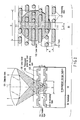
- FIG. 1 is a view for explaining the basic concept of a data recording method on information storage medium (recordable optical disc using a blue laser) 9 according to an embodiment of the present invention.
- FIG. 2 schematically shows the structure of this information storage medium (one-sided, two-layered type) 9.
- phase change type first recording layer 123 is formed on substrate 90 of medium 9, intermediate layer 124 which has thickness t and refractive index n is formed thereon, phase change type 0th recording layer 122 is formed thereon, and transparent protection layer 125 (having a thickness of about 100 ⁇ m) is formed thereon.
- fine pre-grooves are spirally or concentrically formed as embossed patterns, and form tracks 112.
- recording marks 127 in (b) of FIG. 2) on the recording layer (122 or 123 in (a) of FIG. 2) along tracks 112, information is recorded.
- information is recorded or rewritten for respective continuous data recording units (110a, 110b, and 110c in FIG. 1) where recording marks 127 are continuously formed, thus forming recording marks 127.
- gaps 111b and 111c with length ⁇ are formed between neighboring continuous data recording units 110a, 110b, and 110c.
- the gist of the data recording method according to this embodiment resides in formation of predetermined gap ⁇ between neighboring data recording units.
- gaps 111b and 111c are formed between neighboring continuous data recording units 110a, 110b, and 110c, as shown in FIG. 1, these gaps ( ⁇ ) absorb the influence (jitter) of rotation nonuniformity of a spindle motor (204 in FIG. 6 to be described later) that rotates disc-shaped medium 9. That is, since this gap (e.g., 111b) is formed, even when large jitter is produced due to rotation nonuniformity of a rotation driving system upon information recording, an overlapping portion can be prevented from being formed between neighboring continuous data recording units (e.g., 110a and 110b), and data in each continuous data recording unit 110 can be stably and easily rewritten. This is a large feature obtained by the data recording method that forms gap ⁇ between neighboring data recording units.
- This embodiment adopts CLV (Constant Linear Velocity) recording in which length ⁇ of each gap 111 and length L of each continuous data recording unit 110 always become constant independently of the radial position in information storage medium 9.
- a data structure in continuous data recording unit 110 is formed by recording synchronization VFO (Variable Frequency Oscillator) area 113 formed at the beginning of continuous data recording unit 110, and recording area 114 which follows area 113.
- VFO Very Frequency Oscillator
- the contents of recorded information 114 in FIG. 1 are obtained by modulating and recording data of one whole ECC block (e.g., data as a combination of small ECC block 8-0 in (f) of FIG. 4 to be described later and small ECC block 8-1 in (g) of FIG. 4).
- the contents upon practicing the present invention are not limited to these contents.
- the practice contents of the present invention include a case wherein recorded information 114 is made up of a plurality of ECC blocks or of a fraction of an integer of data in one ECC block.
- one recorded information 114 may be formed of one or a plurality of pieces of physical sector information 4 shown in FIG. 3 (to be described later).
- laser beam (its wavelength ⁇ is around 405 nm) 120 is focused on first recording layer 123 via objective lens 121 (its numerical aperture NA is, for example, around 0.85), and information recorded on first recording layer 123 is reproduced by detecting a change in amount of light reflected by first recording layer 123, as shown in (a) of FIG. 2.
- some light components of laser beam 120 are reflected by 0th recording layer 122, pass through objective lens 121 again, and leak into detection light.
- D the diameter of laser beam 120 that strikes 0th recording layer 122
- NA the numerical aperture of objective lens 121
- n the refractive index of intermediate layer 124
- t the thickness of intermediate layer 124 under the condition that the laser beam is focused on first recording layer 123 shown in (a) of FIG. 2.
- D 2t tan ⁇ sin -1 (NA/n) ⁇
- laser beam 120 may completely fall within the region where the plurality of neighboring gaps 111 align (not shown). At this time, the region of laser beam 120 with diameter D contains no recording marks 127 at all, i.e., corresponds to an unrecorded state (which will be referred to as state ⁇ hereinafter for the sake of simplicity).
- ⁇ ⁇ D i.e., a state that satisfies: ⁇ ⁇ 2t tan ⁇ sin -1 (NA/n) ⁇ is set
- ⁇ ⁇ 2t tan ⁇ sin -1 (NA/n) ⁇ a change in amount of laser beam 120 reflected by 0th recording layer 122 (i.e., inter-layer crosstalk) when laser beam 120 passes by the region where gaps 111 align becomes smaller than the difference between states ⁇ and ⁇ described above.
- gaps 111b and 111c are laid out between neighboring continuous recording units 110a, 110b, and 110c, and gaps 111b and 111c are set to have small length ⁇ , an inter-layer crosstalk amount upon reproduction of one-sided, multi-layered disc can be reduced.
- a large characteristic feature of this embodiment lies in this point.
- ⁇ ⁇ D/4 i.e., ⁇ ⁇ ttan ⁇ sin -1 (NA/n) ⁇ /2
- ⁇ ⁇ D/4 i.e., ⁇ ⁇ ttan ⁇ sin -1 (NA/n) ⁇ /2
- gap ⁇ is ⁇ ⁇ 64 ⁇ m from inequality (4).
- data are recorded along tracks by CLV.
- the positions of gaps 111 are different from each other between neighboring tracks.
- gaps 111 are arranged at neighboring positions between neighboring tracks, and gap regions 111 align in the radial direction of information storage medium 9, as shown in (b) of FIG. 2.
- the physical periodic length of gaps 111 is changed in the direction along tracks 112 to lay out gaps 111 at non-neighboring positions between neighboring tracks.
- a characteristic feature of the present invention also lies in this point.
- FIG. 3 is a view for explaining the configuration of physical sector data recorded on the information storage medium according to the embodiment of the present invention.
- FIG. 4 is a view for explaining a method of forming an ECC block with respect to physical sector data shown in FIG. 3. The concept associated with the structure in an ECC block in the embodiment of the present invention will be explained below with reference to FIGS. 3 and 4.
- AV information and stream information which are transferred continuously, are broken up into small pieces, which are converted into pack structures appended with pack headers, and these packs are recorded on information storage medium (optical disc) 9. That is, as shown in (a) of FIG. 3, video information and audio information are transferred while being arranged along the time axis in the form of video packs 1-0, 1-1, 1-2,..., and audio packs 2-0, 2-1, 2-2,.... Each of video packs 1-0,... and audio packs 2-0,... has a data size of 2048 bytes, which match the logical sector information size. Video packs 1-0,... and audio packs 2-0,... are abstractly handled as a plurality of pieces of logical sector information 3-1 to 3-31 in the logical layer, as shown in (b) of FIG. 3. (That is, examples of practical contents of the plurality of pieces of logical sector information 3-1 to 3-31 correspond to video packs 1-0,... and audio packs 2-0,.7)
- each physical sector information (4-0 to 4-31) has the following configuration. That is, 4-byte PID information, 2-byte IED information, and a 10-byte reserve field (the size in an existing DVD is 6 bytes) are arranged at the head of each information, and 4-byte EDC is arranged at the end of information (data 0-0-0 to data 0-0-5). After that, that sequence is broken up into 188-byte data (each of data 0-0-0 to data 0-0-5), error correction PI (inner-code parity) data (PI0-0-0 to PI0-0-5) are appended to every 188-byte data, and these data are arranged in turn, as shown in (d) of FIG. 3 or (d) of FIG. 4. In odd-numbered physical sector data (first physical sector data 5-0), PO (outer-code parity) data (PO0) is arranged at the end of data to complete physical sector data 5-0.
- PI inner-code parity
- the embodiment of the present invention is characterized in that even-numbered physical sector data (second physical sector data 5-1) has a structure in which PO data (PO1) is arranged in the second column from the end of data, and data 1-1-5 and PI data (PI1-1-5) are arranged at the end of the even-numbered physical sector data.
- Physical sector data 5-0 to 5-31, which are completed in this manner, are recorded on an optical disc (information storage medium 9) in accordance with the order they are arranged, as shown in (e) of FIG. 3.
- one physical sector data 5-0 is formed as a combination of data in two different small ECC blocks 8-0 and 8-1.
- ECC blocks 8-0 and 8-1 small units shown in (f) and (g) of FIG. 4 are called small ECC blocks, and a combination of two small ECC blocks 8-0 and 8-1 as a whole is called a general ECC block.
- data in physical sector data 5-0 is finely broken up into 200-byte data, and 188-byte data 0-0-0 and PI data 0-0-0 are arranged in the first row in ECC block 8-0.
- Next 188-byte data 0-1-0 and PI 0-1-0 in physical sector data 5-0 are arranged in the first row in small ECC block 8-1.
- Next 188-byte data 0-0-1 and PI data 0-0-1 are arranged on the second row in ECC block 8-0.
- first 200 bytes are inserted in the sixth row in small ECC block 8-1 as PO0.
- data from data 0-0-0 to PO0 form physical sector data 5-0.
- First data 1-0-0 and PI 1-0-0 that follows the first data in next physical sector data 5-1 are arranged in the seventh row in ECC block 8-0, as shown in (f) of FIG. 4.
- first 200-byte data is arranged as PO1 in the 12th row in ECC block 8-0.
- PO data (PO0, PO1) for respective rows (200 bytes) are arranged at equal intervals for respective physical sector data 5-0 to 5-31, and their arrangement positions have a difference for one physical sector data between a pair of small ECC blocks 8-0 and 8-1.
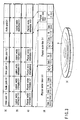
- FIG. 5 is a view for explaining the internal structure of an ECC block recorded on the information storage medium according to the embodiment of the present invention.
- FIG. 5 exemplifies the detailed structure in small ECC block 8-0 or 8-1 shown in (f) or (g) of FIG. 4. Note that the numerals assigned to "sectors" in FIG. 5 indicate row numbers of data sectors.
- FIG. 5 shows a combined state of two, right and left (for each 200-byte column) small ECC blocks.
- Each small ECC block has a structure in which 12-byte PI data is appended every 188 bytes, and PO data for 16 rows is appended.
- the PO data for 16 rows is decomposed into row data, each of which is interleaved and inserted at every 12-row positions.
- a hatched portion of 200-byte columns per row in FIG. 5 means interleaved and inserted PO data.
- the user information size assigned per sector is 2048 bytes as in an existing DVD, and information having the same contents as those of logical sector information recognized in the application layer is set as each physical sector information (main data).
- Main data information having the same contents as those of logical sector information recognized in the application layer is set as each physical sector information (main data).
- Four-byte data ID information, 2-byte IED information, and 10-byte reserve field are arranged at the head of 2048 bytes of the main data (physical sector information), and 4-byte EDC data is arranged at the end of the main data, thus forming all data of a physical sector.
- one physical sector data is interleaved across two small ECC blocks (i.e., within a general ECC block), an error-correctable burst error length can be improved to nearly twice that of the prior art. That is, one physical sector data is broken up into 188-byte data, each of which forms one row data by appending 12-byte PI data (since the existing PI size is 10 bytes, and is increased to 12 bytes, error correction performance per row can be improved), and these row data are alternately and sequentially arranged in right and left different ECC blocks. This is also one of the characteristic features of this embodiment.
- Data (data sector) in one physical sector has an odd number of rows, i.e., 11 rows. This is also a characteristic feature of this embodiment. Since the data sector is made up of an odd number of rows, the total number of rows can be even upon inserting one PO row in each physical sector, and the PO row can be properly inserted in two small ECC blocks (i.e., one general ECC block) without forming any odd row.
- PID information is always arranged at the head position (upper left corner position in FIG. 5) of each physical sector, and the PO insert positions are devised to allow efficient interleave insertion of PO data in the embodiment shown in FIG. 5. That is, PO data is arranged at the last row position of an even sector, and PO data is arranged at the second row position from the end of the sector in an odd sector. As a result, PO data are arranged in a single ECC block, and all physical sectors can have the same data size. This is also a characteristic feature of this embodiment.
- An information recording/reproduction unit executes the following processes are done. That is,
- the information recording/reproduction unit executes the following processes. That is,
- Optical head 202 basically comprises a semiconductor laser element (not shown) as a light source, a photodetector, and an objective lens.
- a laser beam emitted by the semiconductor laser element is focused on information storage medium (optical disc) 9 via the objective lens (121 in FIG. 2).
- the laser beam reflected by a light reflection film or light reflective recording film (122 or 123 in FIG. 2) of information storage medium (optical disc) 9 is photoelectrically converted by the photodetector.
- a detection current obtained by the photodetector undergoes current-voltage conversion by amplifier 213 to obtain a detection signal. This detection signal is processed by focus/track error detection circuit 217 or binarization circuit 212.
- the photodetector is divided into a plurality of photodetection regions, which individually detect changes in amount of light with which the respective photodetection regions are irradiated. Respective detection signals undergo sum/difference calculations by the focus/track error detection circuit 217, thus detecting focus and track errors. In this way, a change in amount of light reflected by the light reflection film or light reflective recording film of information storage medium (optical disc) 9 is detected, thereby reproducing signal c on information storage medium 9.
- the objective lens (121 in FIG. 2) that focuses a laser beam emitted by the semiconductor laser element on information storage medium 9 is movable in two axis directions in accordance with an output current from objective lens actuator driving circuit 218.
- the objective lens moves:
- Such objective lens moving mechanism is called an objective lens actuator.
- Rotation control system (zone CAV rotation control) of information storage medium (optical disc)
- Information storage medium (optical disc) 9 is mounted on turn table 221 which is rotated by the driving force of spindle motor 204.
- the rotational speed (rotational velocity) of information storage medium 9 is detected based on a reproduction signal obtained from information storage medium 9. That is, the detection signal (analog signal) output from amplifier 213 is converted into a digital signal by binarization circuit 212, and PLL (Phase Lock Loop) circuit 211 generates a constant period signal (reference clock signal) based on that digital signal.
- Information storage medium rotational speed detection circuit 214 detects the rotational speed of information storage medium 9 using this signal, and outputs the detection value.
- a correspondence table of the information storage medium rotational speed which corresponds to the radial position where data is reproduced or recorded/erased on information storage medium 9 is pre-stored in semiconductor memory 219.
- controller 220 sets a target rotational speed of information storage medium 9 by looking up information recorded in semiconductor memory 219, and sends that value to spindle motor driving circuit 215.
- Spindle motor driving circuit 215 calculates the difference between this target rotational speed and the output signal (current rotational speed) of information storage medium rotational speed detection circuit 214, and supplies the driving current corresponding to that difference to spindle motor 204, thus controlling the rotational speed of spindle motor 204 to be constant.
- the output signal from information storage medium rotational speed detection circuit 214 is a pulse signal having a frequency corresponding to the rotational speed of information storage medium 9, and spindle motor driving circuit 215 controls both the frequency and pulse phase of this signal.
- Information storage medium (optical disc) 9 is mounted on turn table 221 which is rotated by the driving force of spindle motor 204.
- the rotational speed (rotational velocity) of information storage medium 9 is detected based on a reproduction signal obtained from a wobbled groove region (143 in FIG. 12 or the like) present on information storage medium 9. That is, the detection signal (analog signal) output from focus/track error detection circuit 217 is converted into a digital signal by a binarization circuit (not shown) in information storage medium rotational speed detection circuit 214, thus generating a constant period signal (reference signal).
- Rotational speed detection circuit 214 detects the rotational speed of information storage medium 9 using this reference signal, and outputs a difference signal corresponding to the frequency/phase difference between that detection value and a reference clock signal. Based on this difference signal output value, spindle motor driving circuit 215 supplies a predetermined driving current to spindle motor 204 to make control to attain a constant linear velocity (CLV).
- CLV constant linear velocity
- optical head moving mechanism (feed motor) 203 is equipped.
- a circuit for supplying a driving current to an objective lens actuator (not shown) in optical head 202 in accordance with the output signal (detection signal) from focus/track error detection circuit 217 is arranged.
- This circuit is objective lens actuator driving circuit 218.
- This circuit 218 includes a phase compensation circuit for improving characteristics in correspondence with the frequency characteristics of the objective lens actuator to attain quick response of objective lens movement up to the high frequency range.
- objective lens actuator driving circuit 218 executes:
- Information that indicates locations and contents of information recorded on storage medium 9 varies depending on the types of information storage medium 9, and is generally recorded in directory management regions, navigation packs, or the like in information storage medium 9.
- the directory management regions are recorded together in the inner or outer peripheral region of information storage medium 9.
- the navigation pack is contained in a VOBS (Video Object Set) complying with the data structure of a PS (Program Stream) of MPEG2, and records information indicating the location of the next video data.
- VOBS Video Object Set
- Controller 220 calculates the radial position of the access destination, and detects the distance between that position and the current position of optical head 202. As for the moving distance of optical head 202, velocity curve information that allows the head to reach the target position within a shortest period of time is stored in advance in semiconductor memory 219. Controller 220 reads that information, and controls movement of optical head 202 by the following method in accordance with the velocity curve.
- controller 220 issues a command to objective lens actuator driving circuit 218 to disable the track loop, and then controls feed motor driving circuit 216 to start movement of optical head 202.
- focus/track error detection circuit 217 When the focused beam spot has crossed a track on information storage medium 9, focus/track error detection circuit 217 generates a track error detection signal. Using this track error detection signal, the relative velocity of the focused beam spot with respect to information storage medium 9 can be detected.
- Feed motor driving circuit 216 calculates the difference between the relative velocity of the focused beam spot obtained from focus/track error detection circuit 217, and target velocity information sent from controller 220, and feeds back that result to the driving current to be supplied to optical head driving mechanism (feed motor) 203, thus moving optical head 202.
- optical head moving mechanism (feed motor) 203 In “optical head moving mechanism (feed motor) 203" mentioned above, a frictional force always acts between a guide shaft and bushing or bearing (not shown). When the optical head moves at high speed, dynamic friction acts. However, since the moving velocity of optical head 202 is low at the beginning of movement and immediately before stop, static friction acts. At that time, since the relative frictional force increases, the amplification factor (gain) of a current to be supplied to optical head driving mechanism (feed motor) 203 is increased in response to a command from controller (especially, immediately before stop).
- controller 220 issues a command to objective lens actuator driving circuit 218 to enable the track loop.
- the focused beam spot reproduces an address or track number of that portion while tracing along a track on information storage medium 9.
- the current focused beam spot position is detected from that address or track number, and controller 220 calculates the number of error tracks from the reached target position and informs objective lens actuator driving circuit 218 of the number of tracks required to move the focused beam spot.
- objective lens actuator driving circuit 218 When objective lens actuator driving circuit 218 generates a pair of kick pulses, the objective lens slightly moves in the radial direction of information storage medium 9, thus moving the focused beam spot to the neighboring track.
- the track loop is temporarily disabled, and after kick pulses are generated a given number of times corresponding to the information from controller 220, the track loop is enabled again.
- controller 220 reproduces information (address or track number) at the position where the focused beam spot traces, and confirms if it has accessed a target track.
- a track error detection signal output from focus/track error detection circuit 217 is input to feed motor driving circuit 216.
- controller 220 controls feed motor driving circuit 216 not to use the track error detection signal.
- some components of the track error detection signal are supplied as a driving current to optical head driving mechanism (feed motor) 203. This control continues during the period in which a reproduction or recording/erase process is done continuously.
- information storage medium 9 is mounted so that its central position has a slight eccentricity from that of turn table 221.
- entire optical head 202 slightly moves in correspondence with the eccentricity.
- the focused beam spot position gradually moves toward the outer or inner periphery.
- optical head moving mechanism (feed motor) 203 optical head 202 gradually moves toward the outer or inner periphery in correspondence with that current. In this manner, the load on track error correction of the objective lens actuator is reduced, thus attaining a stable track loop.
- Information to be recorded on information storage medium 9 is input to data input/output interface 222 as recording signal d in the form of a raw signal.
- This recording signal d is directly recorded in semiconductor memory 219, and then undergoes an ECC appending process, as described above, in ECC encoding circuit 208.
- ECC encoding circuit 208 Upon completion of appending of inner-code PI and outer-code PO, ECC encoding circuit 208 reads data for one sector from semiconductor memory 219, and transfers the read data to modulation circuit 207.
- Modulation circuit 207 and demodulation circuit 210 include a conversion table indicating the relationship between a source signal and modulated signal.
- the signal transferred from ECC encoding circuit 208 is segmented into data each consisting of a plurality of bits in accordance with a modulation scheme, and the segmented data are converted into other signals (codes) by looking up the conversion table.
- Semiconductor laser driving circuit 205 operates to record information from optical head 202 on information storage medium 9. At this time, as shown in FIG. 1 and (b) of FIG. 2, recording marks 127 are continuously formed along tracks 112 for respective continuous data recording units 110, and gaps 111 are formed between neighboring continuous data recording units 110.
- each continuous data recording unit (110, 131) is made up of one whole ECC block (130a) or a fraction of an integer (e.g., 133 or 134 in FIG. 8) of one ECC block (130b), as shown in FIG. 8.
- a fraction of an integer of one ECC block indicates a case wherein one ECC block (130b) contains a plurality of physical sectors (e.g., 7-0 to 7-31 in FIG. 8), and a fraction of an integer of the plurality of physical sectors (7-0 to 7-15 or 7-16 to 7-31; 1/2 in this case) form one continuous data recording unit (133 or 134).
- Binarization circuit 212 converts that signal into a binary digital signal consisting of "1" and "0" using a comparator.
- PLL circuit 211 extracts a reference signal upon reproducing information.
- PLL circuit 211 incorporates a variable frequency oscillator. The frequency and phase of a pulse signal (reference clock) output from the oscillator are compared with those of the output signal from the binarization circuit 212, and the comparison results are fed back to the oscillator output.
- Demodulation circuit 210 incorporates a conversion table (not shown) indicating the relationship between modulated and demodulated signals.
- a modulated signal is restored to an original signal by looking up the conversion table in synchronism with the reference clock obtained by PLL circuit 211.
- the restored (demodulated) signal is recorded in semiconductor memory 219.
- Error correction circuit 209 detects any errors of a signal saved in semiconductor memory 219 using inner-code PI and outer-code PO, and sets pointer flags of error positions. After that, error correction circuit 209 corrects a signal at the error positions in accordance with the error pointer flags while reading out the signal from semiconductor memory 219, removes inner-code PI and outer-code PO, and transfers the signal to data input/output interface 222.
- a signal sent from ECC encoding circuit 208 is output as reproduction signal c from data input/output interface 222.
- control program/parameter ROM 220b in controller 220 Parameters used in the control sequences of respective processes and the respective processes in the apparatus shown in FIG. 6 are written in control program/parameter ROM 220b in controller 220 as firmware.
- a microprocessing unit MPU (not shown) of controller 220 executes a control program in ROM 220b using worm RAM 220a as a work area, thus executing the aforementioned processes.
- FIG. 7 shows the sequence of the data conversion process (format conversion process) shown in FIGS. 3 to 5.
- step ST1 physical sector information is set (step ST1).
- a plurality of pieces of physical sector information 4-0 to 4-31 ((c) of FIG. 3) are set (segmented into main data in units of 2048 bytes).
- the plurality of pieces of physical sector information 4-0 to 4-31 are set in correspondence with the size of a plurality of pieces of logical sector information 3-0 to 3-31 ((b) of FIG. 3). That is, user data to be recorded is handled in units of 2048 bytes.
- a 2068-byte data sector is generated from 2048-byte main data, 16-byte auxiliary data, and a 4-byte error detection code (EDC) (step ST2).
- EDC 4-byte error detection code
- the 16-byte auxiliary data contains 4-byte data ID data (PID), a 2-byte error detection code (IED) for the data ID, and 10-byte reserve data (RSV).
- the PID records a sector number used to identify a data sector, and sector information used to identify the contents of the data sector.
- the IED is used to detect any errors generated in the PID portion.
- the RSV is used to record other kinds of auxiliary information (e.g., copyright management information).
- the EDC is used to detect any errors generated in 2064-byte main data and auxiliary data.
- the data sectors are arranged in a 188 (columns) ⁇ 11 (rows) matrix.
- Scramble data is added to 2048-byte main data of each data sector (step ST3).
- Data sector rows are re-arranged depending on whether the sector number is even or odd (step ST4).
- a sector block is generated by vertically stacking 32 continuous data sectors, which are re-arranged depending on their sector numbers (step ST5).
- the data sectors which are vertically stacked are arranged in a 376 (columns) ⁇ 176 (rows) matrix.
- the sector block is horizontally segmented into two blocks to encode error correction codes (step ST6).
- the 188 (columns) ⁇ 176 (rows) blocks after segmentation undergo encoding in the column direction to generate outer-code parity data (PO) for 16 rows.
- This outer code uses a REED Solomon code of RS(192, 176, 17).
- inner-code encoding is done in the row direction to generate inner-code parity data (PI) for 12 columns.
- This inner code uses a REED Solomon code of RS(200, 188, 13).
- the ECC block undergoes row interleave to distribute 16 right and left rows of PO data into the block (step ST7; see FIG. 5).
- PO rows of the left block of the two horizontally segmented blocks are inserted after the lowermost row of an odd sector consisting of only five rows
- PO rows of the right block of the two horizontally segmented blocks are inserted after the lowermost row of an even sector consisting of only five rows.
- step ST8 physical sector data is completed.
- step ST9 zigzag recording across two rows is done.
- a modulation process is executed (step ST10).
- the characteristic feature of the recording data sequence does not match the recording characteristics of medium 9, and efficient recording cannot be done.
- a data pattern is converted according to a predetermined conversion rule.
- the modulation scheme includes an 8/16 modulation scheme for converting 1-byte data into a 16-bit pattern, an 8/12 modulation scheme for converting 1-byte data into a 1.5-byte pattern, a 12/18 modulation scheme for converting 12-bit data into an 18-bit pattern, and the like. Any one of these schemes comprises a plurality of conversion tables and a logic circuit for selecting the conversion table.
- the 12/18 modulation scheme that converts 1.5-byte data has a characteristic of expanding an error at one position to 1.5 bytes, it is effective for the process executed in step ST9 to distribute errors upon reproduction.
- step ST9 zigzag recording according to the setup in step ST9 is done for medium 9.
- data recording is continuously done for respective continuous data recording units 110, as shown in FIG. 1.
- recording is controlled to form gaps 111 with length ⁇ between neighboring continuous data recording units 110.
- FIG. 8 is a view for explaining the data recording method on the information storage medium (recordable optical disc using a blue laser) according to another embodiment of the present invention.
- the physical data length of recording information 114 in FIG. 1 nearly matches the data length (the length of ECC block 130a in FIG. 8) after modulation of data of the ECC block shown in FIGS. 3 and 4, as described above.
- ECC block 130b is segmented into two blocks, and continuous data recording unit 131b which is obtained by appending VFO field 113b to former half data 133 of ECC block 130b to have physical length J is recorded in the direction of tracks 112.
- Gap 111c with length ⁇ is formed after such continuous data recording unit 131b, and continuous data recording unit 131c obtained by appending VFO field 113c to latter half data 133 of ECC block 130b to have physical length J is recorded after gap 111c in the direction of tracks 112.
- length " ⁇ + J + ⁇ + J" is different from length L + ⁇ , gaps 111 do not come to neighboring positions between neighboring tracks (112a and 112b) at that radial position (the radial positions of tracks 112a and 112b in FIG. 8).
- the half of data obtained by modulating ECC block 130b is recorded and arranged in continuous data recording unit 131.
- the scope of the present invention is not limited to this.
- a plurality of arbitrary physical sector data (7-0 to 7-15 and 7-16 to 7-31 in the example in FIG. 8) may be recorded and arranged, or a plurality of ECC blocks 130 may be recorded and arranged together in single continuous data recording unit 131.
- FIG. 9 is a view for explaining necessity of gaps (groove gaps) ⁇ in the information storage medium according to the present invention.
- recording layers 122 and 123 of information storage medium 9 are made up of a phase-change type recording film, data overlap portion 116 is overwritten by rear data of leading continuous data recording unit 110a, and first data of continuous data recording unit 110b is destroyed.
- Rotation control of spindle motor 204 is made using a wobble signal obtained from wobbled groove 143 shown in FIG. 12. Therefore, let f be the rotation nonuniformity amount of spindle motor 204, and ⁇ be the wobble period of wobbled groove 143. Then, the shift amount of last data of continuous data recording unit 110a due to rotation nonuniformity of spindle motor 204 is given by " ⁇ f".
- length ⁇ of gap 111 must be set to satisfy: ⁇ ⁇ ⁇ f
- the rotation nonuniformity amount of spindle motor 204 (the practical rotation nonuniformity amount, including the influence of eccentricity, of optical disc 9, which is actually set on table 221 rotated by motor 204) normally depends on the eccentricity of information storage medium 9. If the eccentricity of information storage medium 9 is ⁇ 100 ⁇ m, rotation nonuniformity amount f due to this eccentricity is around 0.1%. In this case, inequality (7) is rewritten as: ⁇ ⁇ 0.001 ⁇
- Inequality (7) or (8) can define the lower limit of gap ⁇ , and inequality (4), (5), or (6) mentioned above can define the upper limit of gap ⁇ .
- gap ⁇ the lower limit of which is defined by inequality (7) or (8) cannot often satisfy inequality (6) ( ⁇ ⁇ D/4 or ⁇ ⁇ ttan ⁇ sin -1 (NA/n) ⁇ /2) mentioned above due to (practical) rotation nonuniformity of spindle motor 204 or other factors. A measure against such case will be explained below.
- FIG. 10 shows an application (modification) of FIG. 8.
- the physical periodic length of gaps 111 is changed to lay out gaps 111 at non-neighboring positions between neighboring tracks (112a and 112b).
- the physical periodic length of gaps 111 is not macroscopically changed, but the position of gap 111 is shifted at only a position where gaps may be located at neighboring positions between neighboring tracks (112a and 112b).
- each ECC block 130b is segmented into two blocks, 16 sectors from physical sectors 7-0 to 7-15 are assigned to continuous data recording unit 131b as former half data 133 of ECC block 130b, and another 16 sectors from physical sectors 7-16 to 7-31 are assigned to continuous data recording unit 131c as latter half data 134 of ECC block 130b.
- FIG. 11 is a view for explaining the maximum allowable range of gaps (groove gaps) on the information storage medium according to the present invention.
- the embodiment of the present invention adopts CLV (Constant Linear Velocity) as the recording method.
- CLV Constant Linear Velocity
- gaps 111a to 111f with sufficiently small length ⁇ 2 are present in FIG. 11, the influence of inter-layer crosstalk may be relatively small.
- gaps 115a to 115f with sufficiently large length ⁇ 1 are present, no recording mark is present within most of the area in laser beam 120 in the state shown in FIG. 11, and large inter-layer crosstalk appears.
- inequality (16) is rewritten as: ⁇ ⁇ ⁇ (D + Pt)D/Pt That is, inequality (19) must be satisfied as the inter-layer crosstalk reduction that pertains to length ⁇ of gaps.
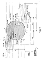
- FIG. 12 is a view for explaining an information storage medium formed with a mark that determines a recording start position according to still another embodiment of the present invention.
- Recording start position determination mark 141 recorded on information storage medium 9 is reproduced by optical head 202 in FIG. 6, and is sent to focus/track error detection circuit 217 via amplifier 213.
- focus/track error detection circuit 217 the presence/absence of mark 141 is detected as a given component of a track error detection signal. Note that the frequency of a detection signal obtained from recording start position determination mark 141 is much higher than that of the track error detection signal. For this reason, by frequency-separating these two signals, mark 141 can be easily detected. Since the two signals have a large frequency difference, the adverse influence of the presence of mark 141 on the track error detection signal can be reduced.
- a wobbled pattern (repeated pattern of 2 ⁇ and ⁇ ) of the recording start position determination mark 141 portion is different from that (repeated pattern of ⁇ alone) of a portion other than the mark. That is, the mark 141 portion has a unique wobbled pattern (a kind of address). For this reason, the detected "repeated pattern of 2 ⁇ and ⁇ " can be reliably determined (specified) as mark 141.
- gaps 111 have different positions in the direction of rotation angle depending on radial positions of information storage medium 9, and the position of recording start position determination mark 141 in the direction of rotation angle shifts accordingly, as shown in FIG. 11.
- the radial position of a location where the head currently traces can be detected by detecting only the position of recording start position determination mark 141 in the direction of rotation angle.
- gap 111 or 115 must be set to have small physical length ⁇ ( ⁇ 1 or ⁇ 2 in FIG. 11). In this case, since gap 111 or 115 has sufficiently small physical length ⁇ , when data of only one continuous data recording unit 110 is rewritten, the rewrite start position is required to have high precision. If the rewrite start position precision is low, the previous and next continuous data recording unit positions may be overwritten upon rewriting only one continuous data recording unit 110.
- recording start position determination mark 141 is recorded in advance on medium (recordable optical disc) 9 in the form of wobble modulation. This is a great characteristic feature of the embodiment of the present invention.
- This recording start position determination mark 141 has the following features:
- the gate (detection window) of a high-performance position detection circuit is opened to detect the end position of recording start position determination mark 141 with high precision. Since the physical length of recording preparation region 142 is set to be a specific value in advance, if the end position of recording start position determination mark 141 is detected, the recording process is started after an elapse of a time interval required to pass recording preparation region 142, which is set at the specific value, thus forming recording marks 127 from the head position of continuous data recording unit 110b. In this manner, since recording preparation region 142 is laid out immediately after recording start position determination mark 141, the end position detection precision of recording start position determination mark 141 can be improved.
- the low head position detection precision can be allowed, and a price reduction of a wobble modulation detection circuit can be achieved. Since the end position detection precision of recording start position determination mark 141 is improved, the start position precision of continuous data recording unit 110b can be greatly improved compared to the prior art.
- the groove pattern of recording preparation region 142 in FIG. 12 has the same amplitude and period of that of wobbled groove region 143.
- the pattern of recording start position determination mark 141 As the pattern of recording start position determination mark 141, a single wobble with period "2 ⁇ " and a single wobble with period " ⁇ " are alternately repeated for four cycles, as shown in FIG. 12. However, the number of times of repetition in recording start position determination mark 141 is not limited to four, but an arbitrary number of times of repetition can be selected. The pattern of recording start position determination mark 141 is not limited to that shown in FIG. 12, but an arbitrary pattern can be set as long as conditions (a) to (c) are satisfied within the scope (feature) of the present invention.
- Controller 220 in FIG. 6 receives an instruction indicating a position where information recording is to be done (i.e., recording location of recording information) on information storage medium 9 shown in FIG. 12 or 1 (step ST111).
- step ST112 Before information is recorded or rewritten on information storage medium 9, the position of recording start position determination mark 141 in the direction of rotation angle at the radial position where recording or rewrite is made is predicted on the basis of the recording location instructed in step ST111 (step ST112).
- step ST113 data (corresponding to recording information 114 in FIG. 1 or 133, 134 in FIG. 8/10) of continuous data recording unit 110 (131 in FIG. 8 or 137, 138 in FIG. 10) is generated (step ST113).
- VFO field 113 is appended to the head of data of continuous data recording unit 110 generated in this way (step ST114).
- the recording start position (the position predicted in step ST112) is accessed (step ST115).
- the information recording/reproduction apparatus in FIG. 6 can find mark 141 somewhere in four cycles. If the information recording/reproduction apparatus finds a position within recording start position determination mark 141 (YES in step ST116), the gate (detection window) of a high-performance position detection circuit in the information recording/reproduction apparatus is opened to begin to prepare for detection of the end position of recording start position determination mark 141 with high precision (step ST117).
- step ST116 recording preparation is made during a period which has a pattern end point of mark 141 as a start point and has a duration corresponding to the length of recording preparation region 142 (step ST117).
- control Upon detection of the end position of recording start position determination mark 141 (boundary position between mark 141 and recording preparation region 142), the control waits for an elapse of a predetermined time interval (a period corresponding to the length of recording preparation region 142) required to pass recording preparation region 142, and a continuous recording process corresponding to the length of continuous data recording unit 110 is executed (step ST118).
- a predetermined time interval a period corresponding to the length of recording preparation region 142
- steps ST115 to ST118 are repeated. If data to be recorded does not remain (YES in step ST119), the process in FIG. 13 ends.
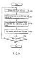
- FIG. 14 is a flow chart for explaining a forming process of gap ⁇ in the recording method according to the embodiment of the present invention.
- optical disc 9 which has wobbled grooves along spiral tracks 112, and continuously undergoes data recording for respective recording units (ECC blocks) along tracks 112 while being rotated is used.
- Step ST20 Data for one ECC block ((f), (g) of FIG. 4) is generated (step ST20), and recording marks 127 corresponding to the generated data are formed on track 112 of disc 9 (step ST21).
- Gap ⁇ (e.g., 111d in FIG. 10) is formed after the end of the recorded ECC block (e.g., 130b in FIG. 10), and the head of the next ECC block (e.g., 130c in FIG. 10) is laid out (step ST22). Recording marks 127 for the next ECC block (130c) are formed on track 112 (step ST23). The aforementioned operations (steps ST20 to ST23) are repeated during recording (NO in step ST24).
- step ST23 when data recording is done (step ST23) while forming predetermined gap ⁇ between neighboring ECC blocks along track 112 (step ST22), the recording system (202 to 208) and rotation driving system (204, 214, 215) in FIG. 6 are controlled so that gap ⁇ satisfies " ⁇ ⁇ ⁇ f" where ⁇ is the wobble period of the wobbled groove and f is the allowable rotation nonuniformity of rotation driving.
- the recording system (202 to 208) and rotation driving system (204, 214, 215) in FIG. 6 are controlled to satisfy at least one of inequalities (4) to (6), inequality (7) or (8), and inequality (19).
- the embodiments include inventions of various stages, and various inventions can be extracted by appropriately combining a plurality of required constituent elements disclosed in this application. For example, even when some required constituent elements are deleted from all the required constituent elements disclosed in the embodiments, the deleted elements are compensated for as needed by known techniques when the extracted invention is practiced.
- Data are continuously recorded for respective ECC blocks (recording units) along tracks 112 on information storage medium 9, and gaps ⁇ are formed between neighboring ECC blocks (recording units) along tracks 112 (FIGS. 1, 12, and the like).
- An information storage medium which has a wobbled groove along spiral tracks (112) and continuously undergoes data recording for respective predetermined recording units (ECC blocks) along the tracks (112) while being rotated, characterized in that the continuous data recording can be done to form a predetermined gap ⁇ between the neighboring predetermined recording units (ECC blocks) along the tracks (112), and the predetermined gap ⁇ satisfies " ⁇ ⁇ ⁇ f" where ⁇ is the wobble period of the wobbled groove and f is the allowable rotation nonuniformity of rotation.
- ⁇ 1B> An information recording method that uses an information storage medium which has a wobbled groove along spiral tracks (112) and continuously undergoes data recording for respective predetermined recording units (ECC blocks) along the tracks (112) while being rotated, characterized in that upon executing the continuous data recording to form a predetermined gap ⁇ between the neighboring predetermined recording units (ECC blocks) along the tracks (112), the predetermined gap ⁇ satisfies " ⁇ ⁇ ⁇ f" where ⁇ is the wobble period of the wobbled groove and f is the allowable rotation nonuniformity of rotation.
- An information recording/reproduction apparatus that uses an information storage medium which has a wobbled groove along spiral tracks (112) and continuously undergoes data recording for respective predetermined recording units (ECC blocks) along the tracks (112) while being rotated, and comprises a spindle motor (204) for rotating the information storage medium (9), recording system means (202 - 208) for forming recording marks (127) for respective predetermined recording units (ECC blocks) on the tracks (112) of the information storage medium (9) rotated by the spindle motor (204), and reproduction system means (202, 203, 213 - 209) for reading information of the recording marks (127) from the information storage medium (9), characterized in that a gap ⁇ which satisfies " ⁇ ⁇ ⁇ f" where ⁇ is the wobble period of the wobbled groove and f is the allowable rotation nonuniformity of the spindle motor (204) is formed between the neighboring predetermined recording units (ECC blocks) along the tracks (112).
- ⁇ 1A> to ⁇ 1C> since recording is done to form a gap ( ⁇ ) between neighboring predetermined recording units (ECC blocks), two successive recording units can be prevented from overlapping even when a rotation driving mechanism (spindle motor) suffers rotation nonuniformity, and recorded data can be prevented from being destroyed (due to destruction of some recording marks when an overlapping portion is formed), thus assuring high data reliability. Since no prepit headers are required unlike the prior art, the capacity can be increased accordingly.
- ⁇ 2A> An information storage medium characterized in that upon continuously executing data recording for respective predetermined recording units (ECC blocks) along the tracks (112) on the information storage medium (9), recording can be done to form a gap ( ⁇ ) between the predetermined recording units (ECC blocks) along the tracks (112).
- ⁇ 2B> An information recording method characterized in that upon continuously executing data recording for respective predetermined recording units (ECC blocks) along the tracks (112) on the information storage medium (9), recording is done (ST22) to form a gap ( ⁇ ) between the predetermined recording units (ECC blocks) along the tracks (112).
- ⁇ 2C> An information recording/reproduction apparatus characterized in that upon continuously executing data recording for respective predetermined recording units (ECC blocks) along the tracks (112) on the information storage medium (9), recording is done to form a gap ( ⁇ ) between the predetermined recording units (ECC blocks) along the tracks (112).
- ECC blocks predetermined recording units
- an information storage medium (9) is a one-sided, recording multilayer (122, 123) type disc-shaped medium (9) having spiral tracks (112) with a track pitch Pt
- ⁇ 3A> to ⁇ 3C> in a one-sided, two-recording layer type information storage medium on which information can be read from a plurality of recording layers from one surface side, even when the already recorded portion and non-recorded portion have a light reflectance difference, inter-layer crosstalk due to the influence of the presence/absence of recording marks on the other recording layer can be greatly reduced, and high reliability of a reproduction signal can be assured.
- ⁇ 4A> An information storage medium characterized in that upon continuously executing data recording for respective recording units (ECC blocks) along spiral tracks (112) on a disc-shaped information storage medium (9) having a center of rotation (center of 10), recording is done to form a gap ( ⁇ ) between the predetermined recording units (ECC blocks) along the tracks (112), and an angular position (A) of the gap (b) formed on one of at least one pair of neighboring tracks (112a, 112b) of the tracks (112) with respect to the center of rotation (center of 10) is different from an angular position (B) of the gap ( ⁇ ) formed in the other (112b) of the neighboring tracks with respect to the center of rotation (center of 10).
- An information recording method that continuously executes data recording for respective recording units (ECC blocks) along spiral tracks (112) on a disc-shaped information storage medium (9) having a center of rotation (center of 10) to form a gap ( ⁇ ) between the predetermined recording units (ECC blocks) along the tracks (112), characterized in that an angular position (A) of the gap ( ⁇ ) formed on one of at least one pair of neighboring tracks (112a, 112b) of the tracks (112) with respect to the center of rotation (center of 10) is different from an angular position (B) of the gap ( ⁇ ) formed in the other (112b) of the neighboring tracks with respect to the center of rotation (center of 10).
- ⁇ 4A> and ⁇ 4B> in a one-sided, two-recording layer type information storage medium on which information can be read from a plurality of recording layers from one surface side, even when the already recorded portion and non-recorded portion have a light reflectance difference, inter-layer crosstalk due to the influence of the presence/absence of recording marks on the other recording layer can be greatly reduced, and high reliability of a reproduction signal can be assured.
- An information storage medium which is a recordable information medium (9) on which data recording is continuously done to form a predetermined gap ( ⁇ ) between neighboring predetermined recording units (ECC blocks) along tracks (112), characterized in that a mark (141; a unique pattern which repeats itself a plurality of number of times at ⁇ + 2 ⁇ ); a kind of address pattern) which indicates a recording start position for the continuous data recording for respective predetermined recording units (ECC blocks) is pre-recorded by wobble modulation of the tracks (112).
- ⁇ 6A> An information recording method characterized in that the information storage medium of ⁇ 5A> is used, and after a mark position indicating a recording start position for continuous data recording is detected (YES in step ST116), continuous recording is started.
- ⁇ 6B> An information recording apparatus characterized in that the information storage medium of ⁇ 5A> is used, and after a mark position indicating a recording start position for continuous data recording is detected (YES in step ST116), continuous recording is started.
Landscapes
- Engineering & Computer Science (AREA)
- Signal Processing (AREA)
- Optical Recording Or Reproduction (AREA)
- Signal Processing For Digital Recording And Reproducing (AREA)
Applications Claiming Priority (2)
| Application Number | Priority Date | Filing Date | Title |
|---|---|---|---|
| JP2001143530A JP2002342942A (ja) | 2001-05-14 | 2001-05-14 | 情報記憶媒体、情報記録方法、および情報記録再生装置 |
| JP2001143530 | 2001-05-14 |
Publications (2)
| Publication Number | Publication Date |
|---|---|
| EP1260980A2 true EP1260980A2 (de) | 2002-11-27 |
| EP1260980A3 EP1260980A3 (de) | 2003-08-13 |
Family
ID=18989666
Family Applications (1)
| Application Number | Title | Priority Date | Filing Date |
|---|---|---|---|
| EP02000608A Withdrawn EP1260980A3 (de) | 2001-05-14 | 2002-01-10 | Informationsaufzeichnungsmedium, Verfahren zur Aufzeichnung von Informationen, und Gerät zur Aufzeichnung/Wiedergabe von Informationen |
Country Status (3)
| Country | Link |
|---|---|
| US (11) | US7075877B2 (de) |
| EP (1) | EP1260980A3 (de) |
| JP (1) | JP2002342942A (de) |
Cited By (2)
| Publication number | Priority date | Publication date | Assignee | Title |
|---|---|---|---|---|
| EP1577884A4 (de) * | 2002-12-17 | 2008-11-19 | Mitsubishi Kagaku Media Co Ltd | Optisches aufzeichnungsmedium, aufzeichnungs-/wiedergabeverfahren für optisches aufzeichnungsmedium und aufzeichnungs-/wiedergabevorrichtung |
| US7801000B2 (en) | 2002-12-17 | 2010-09-21 | Mitsubishi Kagaku Media Co., Ltd. | Recording/reading method for an optical recording medium using an irradiating a laser beam |
Families Citing this family (16)
| Publication number | Priority date | Publication date | Assignee | Title |
|---|---|---|---|---|
| JP2002342942A (ja) * | 2001-05-14 | 2002-11-29 | Toshiba Corp | 情報記憶媒体、情報記録方法、および情報記録再生装置 |
| AU2002354137A1 (en) * | 2002-11-29 | 2004-06-23 | Fujitsu Limited | Data recording and reproducing device, and data recording and reproducing method |
| DK1652178T3 (da) * | 2003-07-07 | 2009-08-24 | Lg Electronics Inc | Registreringsmedium, fremgangsmåde til konfigurering af styreinformation deraf, fremgangsmåde til registrering eller reproduktion af data under anvendelse af samme og apparat dertil |
| KR100953637B1 (ko) * | 2003-07-07 | 2010-04-20 | 엘지전자 주식회사 | 광디스크 및 광디스크의 디스크정보 기록방법 |
| CA2474995C (en) * | 2003-07-07 | 2011-11-22 | Lg Electronics Inc. | Recording medium, method of configuring control information thereof, recording and/or reproducing method using the same, and apparatus thereof |
| US7564760B2 (en) * | 2003-07-09 | 2009-07-21 | Lg Electronics, Inc. | Recording medium, method of configuring disc control information thereof, recording and reproducing method using the same, and apparatus thereof |
| KR101024904B1 (ko) * | 2003-08-14 | 2011-03-31 | 엘지전자 주식회사 | 기록매체, 기록방법, 기록장치 및 기록재생시스템 |
| JP4809765B2 (ja) * | 2003-08-14 | 2011-11-09 | エルジー エレクトロニクス インコーポレイティド | 記録媒体、記録媒体の制御情報構成方法、これを用いた記録及び再生方法、並びにその装置 |
| CA2535263C (en) * | 2003-08-14 | 2012-03-06 | Lg Electronics Inc. | Recording medium, method of configuring control information thereof, recording and reproducing method using the same, and apparatus thereof |
| ES2325662T3 (es) * | 2003-08-14 | 2009-09-11 | Lg Electronics Inc. | Medio de grabacion, metodo de configuracion de informacion de control de dicho medio, metodo de grabacion y/o reproduccion usando dicho medio, y aparato de dicho metodo. |
| US7596069B2 (en) * | 2003-11-25 | 2009-09-29 | Dell Products L.P. | Optical medium aligned information system and method |
| BRPI0510788A (pt) * | 2004-05-13 | 2007-11-20 | Lg Electronics Inc | meio de gravação, método e aparelho de leitura/gravação de meio de gravação |
| KR101041809B1 (ko) * | 2004-07-27 | 2011-06-17 | 엘지전자 주식회사 | 광디스크 및 광디스크 제어정보 구성방법 및 이를 이용한광디스크 기록재생방법과 장치 |
| JP2007080367A (ja) * | 2005-09-13 | 2007-03-29 | Toshiba Corp | 情報記憶媒体、情報記録方法、および情報再生装置 |
| JP4516939B2 (ja) * | 2006-06-23 | 2010-08-04 | 株式会社東芝 | 光ディスク記録装置 |
| US9229813B2 (en) * | 2014-03-06 | 2016-01-05 | HGST Netherlands B.V. | Error correction with on-demand parity sectors in magnetic data storage devices |
Family Cites Families (31)
| Publication number | Priority date | Publication date | Assignee | Title |
|---|---|---|---|---|
| JP2563138B2 (ja) * | 1989-12-19 | 1996-12-11 | 株式会社日立製作所 | 情報記録単位の先頭検出方法,記録再生装置およびディスク記録媒体 |
| JP2760882B2 (ja) * | 1990-05-09 | 1998-06-04 | 株式会社日立製作所 | マルチビーム光デイスク装置及び記録再生方法 |
| US5604725A (en) * | 1993-12-16 | 1997-02-18 | Sharp Kabushiki Kaisha | Information recording method and collector and distributor for recording information |
| JP3456001B2 (ja) | 1994-01-14 | 2003-10-14 | ソニー株式会社 | ディスク状記録媒体、及びその記録及び/又は再生装置 |
| JPH0863905A (ja) * | 1994-08-18 | 1996-03-08 | Hitachi Ltd | 記録再生装置、ディジタル信号処理装置およびエラー訂正方法 |
| US5566150A (en) * | 1994-09-26 | 1996-10-15 | Martin Marietta Corporation | Multibeam optical apparatus and method for tracking control for an optical disk having a set of tracks |
| US6487151B1 (en) * | 1994-12-20 | 2002-11-26 | Matsushita Electric Industrial Co. Ltd. | Optical information recording and reproducing system with overwrite capability and recording medium for use therewith |
| JPH09161402A (ja) | 1995-12-04 | 1997-06-20 | Sony Corp | データ記録・再生方法、光学式ディスク装置および光学式ディスク記録媒体 |
| CN1110799C (zh) * | 1996-02-08 | 2003-06-04 | 松下电器产业株式会社 | 光盘,光盘设备和在光盘上再生信息的方法 |
| JP3850060B2 (ja) | 1996-02-13 | 2006-11-29 | 三菱電機株式会社 | 光ディスク及び光ディスク装置 |
| JP3824701B2 (ja) * | 1996-04-01 | 2006-09-20 | パイオニア株式会社 | 情報記録方法及び装置 |
| DE69724740T2 (de) | 1996-06-03 | 2004-07-08 | Kao Corp. | Optische platte, verfahren zur herstellung der optischen platte und herstellungsgerät dafür |
| US6118753A (en) * | 1996-08-13 | 2000-09-12 | Hewlett-Packard Company | Erasable digital video disk with reference clock track |
| JPH113565A (ja) * | 1997-06-11 | 1999-01-06 | Hitachi Ltd | データ記録再生方法及びその装置 |
| JPH117631A (ja) | 1997-06-17 | 1999-01-12 | Toshiba Corp | 光ディスク及び光ディスクフォーマット装置 |
| JP3972348B2 (ja) | 1997-07-02 | 2007-09-05 | ソニー株式会社 | 情報記録再生装置および方法、並びに伝送媒体 |
| US6252845B1 (en) * | 1997-08-05 | 2001-06-26 | Matsushita Electric Industrial Co., Ltd. | High density optical disk, apparatus for reproducing optical disk and method for producing optical disk master |
| CN1324580C (zh) * | 1997-11-26 | 2007-07-04 | 松下电器产业株式会社 | 聚焦位置调整装置及光盘驱动装置 |
| JP4078696B2 (ja) * | 1997-11-28 | 2008-04-23 | 松下電器産業株式会社 | 記録許可判定装置及び情報記録装置 |
| EP0926664B1 (de) * | 1997-12-26 | 2006-05-31 | Kabushiki Kaisha Toshiba | Optische Platte und optisches Plattengerät |
| JP4066289B2 (ja) * | 1999-01-08 | 2008-03-26 | パイオニア株式会社 | 情報記録方法 |
| JP2000215452A (ja) * | 1999-01-19 | 2000-08-04 | Victor Co Of Japan Ltd | 光ディスク記録再生装置及び光ディスク |
| CN1203471C (zh) * | 1999-01-29 | 2005-05-25 | 松下电器产业株式会社 | 使用了盘状存储媒体的跟踪方法和地址重放方法 |
| JP4061773B2 (ja) | 1999-04-15 | 2008-03-19 | ヤマハ株式会社 | 記録可能型clv方式光ディスクおよびその記録装置 |
| JP2000305716A (ja) * | 1999-04-23 | 2000-11-02 | Sony Corp | ディスク制御装置及びディスク制御方法 |
| JP2000311367A (ja) * | 1999-04-23 | 2000-11-07 | Sony Corp | ディスクドライブ装置、及びトラッキング制御方法 |
| JP2001084598A (ja) * | 1999-09-14 | 2001-03-30 | Canon Inc | 光情報記録媒体 |
| US6401169B1 (en) * | 1999-11-23 | 2002-06-04 | Roxio, Inc. | Optical disc buffer under-run handling method |
| US6405283B1 (en) * | 1999-11-23 | 2002-06-11 | Roxio, Inc. | Method for handling buffer under-run during disc recording |
| JP2002279649A (ja) * | 2001-03-22 | 2002-09-27 | Toshiba Corp | 記録媒体及び信号記録方法及び装置及び再生装置 |
| JP2002342942A (ja) * | 2001-05-14 | 2002-11-29 | Toshiba Corp | 情報記憶媒体、情報記録方法、および情報記録再生装置 |
-
2001
- 2001-05-14 JP JP2001143530A patent/JP2002342942A/ja active Pending
-
2002
- 2002-01-10 EP EP02000608A patent/EP1260980A3/de not_active Withdrawn
- 2002-01-29 US US10/058,084 patent/US7075877B2/en not_active Expired - Fee Related
-
2004
- 2004-10-13 US US10/962,497 patent/US7301878B2/en not_active Expired - Lifetime
-
2006
- 2006-11-21 US US11/562,085 patent/US7379409B2/en not_active Expired - Fee Related
- 2006-11-21 US US11/562,048 patent/US20070076566A1/en not_active Abandoned
- 2006-11-21 US US11/562,057 patent/US7382710B2/en not_active Expired - Fee Related
- 2006-11-21 US US11/562,168 patent/US7408868B2/en not_active Expired - Fee Related
- 2006-11-21 US US11/562,152 patent/US7336594B2/en not_active Expired - Fee Related
- 2006-11-21 US US11/562,074 patent/US7345986B2/en not_active Expired - Fee Related
- 2006-11-21 US US11/562,159 patent/US7339879B2/en not_active Expired - Fee Related
- 2006-11-21 US US11/562,070 patent/US7336593B2/en not_active Expired - Fee Related
-
2008
- 2008-01-09 US US11/971,676 patent/US20080117794A1/en not_active Abandoned
Cited By (2)
| Publication number | Priority date | Publication date | Assignee | Title |
|---|---|---|---|---|
| EP1577884A4 (de) * | 2002-12-17 | 2008-11-19 | Mitsubishi Kagaku Media Co Ltd | Optisches aufzeichnungsmedium, aufzeichnungs-/wiedergabeverfahren für optisches aufzeichnungsmedium und aufzeichnungs-/wiedergabevorrichtung |
| US7801000B2 (en) | 2002-12-17 | 2010-09-21 | Mitsubishi Kagaku Media Co., Ltd. | Recording/reading method for an optical recording medium using an irradiating a laser beam |
Also Published As
| Publication number | Publication date |
|---|---|
| US20070076566A1 (en) | 2007-04-05 |
| EP1260980A3 (de) | 2003-08-13 |
| US7379409B2 (en) | 2008-05-27 |
| US20070086278A1 (en) | 2007-04-19 |
| US7336594B2 (en) | 2008-02-26 |
| US20070076571A1 (en) | 2007-04-05 |
| US7382710B2 (en) | 2008-06-03 |
| US20080117794A1 (en) | 2008-05-22 |
| US20070091778A1 (en) | 2007-04-26 |
| US20070076570A1 (en) | 2007-04-05 |
| US20070076568A1 (en) | 2007-04-05 |
| US20050047298A1 (en) | 2005-03-03 |
| US20070091777A1 (en) | 2007-04-26 |
| US20070091735A1 (en) | 2007-04-26 |
| US7301878B2 (en) | 2007-11-27 |
| US7336593B2 (en) | 2008-02-26 |
| US7339879B2 (en) | 2008-03-04 |
| US7408868B2 (en) | 2008-08-05 |
| US20020167880A1 (en) | 2002-11-14 |
| US7345986B2 (en) | 2008-03-18 |
| JP2002342942A (ja) | 2002-11-29 |
| US7075877B2 (en) | 2006-07-11 |
Similar Documents
| Publication | Publication Date | Title |
|---|---|---|
| US20080117794A1 (en) | Information storage medium, information recording method, and information recording/reproduction apparatus | |
| JP4130534B2 (ja) | 情報記録媒体、情報記録装置、情報記録方法、情報再生装置、及び情報再生方法 | |
| CN1117354C (zh) | 光盘和用于扫描这种光盘的装置 | |
| JP2005063533A (ja) | 情報記録媒体および情報記録媒体への記録方法ならびに情報記録再生装置 | |
| US6996053B2 (en) | Optical recording medium, optical reproduction apparatus, and optical reproduction method | |
| US20020136125A1 (en) | Recording medium, Signal recording method and apparatus and signal reproducing apparatus | |
| US6898171B1 (en) | Information recording medium with index header | |
| JP3998646B2 (ja) | 情報記録再生装置 | |
| JP3545740B2 (ja) | 光ディスク及び光ディスク装置 | |
| JP2004006009A (ja) | 情報記憶媒体、情報記録方法、および情報記録再生装置 | |
| JP2007220293A (ja) | 情報記憶媒体、情報記録方法、および再生装置 | |
| JP4130692B2 (ja) | 情報記録媒体、情報記録装置、情報記録方法、情報再生装置、及び情報再生方法 | |
| JP2002197675A (ja) | 情報記録媒体、情報記録装置、情報記録方法、情報再生装置、及び情報再生方法 | |
| JP2002042348A (ja) | 光ディスク及び光ディスク装置、情報記録方法、情報再生方法 | |
| JP2002237056A (ja) | 光記録媒体および光記録再生装置 |
Legal Events
| Date | Code | Title | Description |
|---|---|---|---|
| PUAI | Public reference made under article 153(3) epc to a published international application that has entered the european phase |
Free format text: ORIGINAL CODE: 0009012 |
|
| 17P | Request for examination filed |
Effective date: 20020110 |
|
| AK | Designated contracting states |
Kind code of ref document: A2 Designated state(s): AT BE CH CY DE DK ES FI FR GB GR IE IT LI LU MC NL PT SE TR |
|
| AX | Request for extension of the european patent |
Free format text: AL;LT;LV;MK;RO;SI |
|
| PUAL | Search report despatched |
Free format text: ORIGINAL CODE: 0009013 |
|
| AK | Designated contracting states |
Designated state(s): AT BE CH CY DE DK ES FI FR GB GR IE IT LI LU MC NL PT SE TR |
|
| AX | Request for extension of the european patent |
Extension state: AL LT LV MK RO SI |
|
| RIC1 | Information provided on ipc code assigned before grant |
Ipc: 7G 11B 19/04 B Ipc: 7G 11B 7/006 B Ipc: 7G 11B 7/13 B Ipc: 7G 11B 7/007 B Ipc: 7G 11B 20/12 A |
|
| AKX | Designation fees paid |
Designated state(s): DE FR GB |
|
| 17Q | First examination report despatched |
Effective date: 20071010 |
|
| STAA | Information on the status of an ep patent application or granted ep patent |
Free format text: STATUS: THE APPLICATION IS DEEMED TO BE WITHDRAWN |
|
| 18D | Application deemed to be withdrawn |
Effective date: 20090801 |