EP1261008A1 - Disjoncteur magnétothermique enfermé - Google Patents
Disjoncteur magnétothermique enfermé Download PDFInfo
- Publication number
- EP1261008A1 EP1261008A1 EP02011147A EP02011147A EP1261008A1 EP 1261008 A1 EP1261008 A1 EP 1261008A1 EP 02011147 A EP02011147 A EP 02011147A EP 02011147 A EP02011147 A EP 02011147A EP 1261008 A1 EP1261008 A1 EP 1261008A1
- Authority
- EP
- European Patent Office
- Prior art keywords
- lever
- circuit breaker
- breaker according
- actuation
- closure
- Prior art date
- Legal status (The legal status is an assumption and is not a legal conclusion. Google has not performed a legal analysis and makes no representation as to the accuracy of the status listed.)
- Granted
Links
- 230000007246 mechanism Effects 0.000 claims abstract description 39
- 238000010791 quenching Methods 0.000 claims abstract description 12
- 230000000171 quenching effect Effects 0.000 claims abstract description 12
- 230000009471 action Effects 0.000 claims description 11
- 230000008878 coupling Effects 0.000 claims description 5
- 238000010168 coupling process Methods 0.000 claims description 5
- 238000005859 coupling reaction Methods 0.000 claims description 5
- 230000002787 reinforcement Effects 0.000 claims description 4
- 238000000926 separation method Methods 0.000 claims description 3
- 230000003213 activating effect Effects 0.000 claims description 2
- 238000005452 bending Methods 0.000 claims description 2
- 238000006243 chemical reaction Methods 0.000 claims description 2
- 238000010891 electric arc Methods 0.000 claims description 2
- 230000014759 maintenance of location Effects 0.000 claims 1
- 230000013011 mating Effects 0.000 claims 1
- 230000008901 benefit Effects 0.000 description 5
- 241000761557 Lamina Species 0.000 description 3
- 239000000463 material Substances 0.000 description 2
- 229920001187 thermosetting polymer Polymers 0.000 description 2
- 238000004519 manufacturing process Methods 0.000 description 1
- 238000012986 modification Methods 0.000 description 1
- 230000004048 modification Effects 0.000 description 1
- 238000005192 partition Methods 0.000 description 1
- 239000012815 thermoplastic material Substances 0.000 description 1
Images




Classifications
-
- H—ELECTRICITY
- H01—ELECTRIC ELEMENTS
- H01H—ELECTRIC SWITCHES; RELAYS; SELECTORS; EMERGENCY PROTECTIVE DEVICES
- H01H71/00—Details of the protective switches or relays covered by groups H01H73/00 - H01H83/00
- H01H71/10—Operating or release mechanisms
- H01H71/50—Manual reset mechanisms which may be also used for manual release
- H01H71/52—Manual reset mechanisms which may be also used for manual release actuated by lever
- H01H71/522—Manual reset mechanisms which may be also used for manual release actuated by lever comprising a cradle-mechanism
- H01H71/525—Manual reset mechanisms which may be also used for manual release actuated by lever comprising a cradle-mechanism comprising a toggle between cradle and contact arm and mechanism spring acting between handle and toggle knee
-
- H—ELECTRICITY
- H01—ELECTRIC ELEMENTS
- H01H—ELECTRIC SWITCHES; RELAYS; SELECTORS; EMERGENCY PROTECTIVE DEVICES
- H01H2300/00—Orthogonal indexing scheme relating to electric switches, relays, selectors or emergency protective devices covered by H01H
- H01H2300/046—Orthogonal indexing scheme relating to electric switches, relays, selectors or emergency protective devices covered by H01H using snap closing mechanisms
- H01H2300/048—Snap closing by latched movable contact, wherein the movable contact is held in a minimal distance from the fixed contact during first phase of closing sequence in which a closing spring is charged
-
- H—ELECTRICITY
- H01—ELECTRIC ELEMENTS
- H01H—ELECTRIC SWITCHES; RELAYS; SELECTORS; EMERGENCY PROTECTIVE DEVICES
- H01H71/00—Details of the protective switches or relays covered by groups H01H73/00 - H01H83/00
- H01H71/10—Operating or release mechanisms
- H01H71/12—Automatic release mechanisms with or without manual release
- H01H71/24—Electromagnetic mechanisms
- H01H71/2409—Electromagnetic mechanisms combined with an electromagnetic current limiting mechanism
-
- H—ELECTRICITY
- H01—ELECTRIC ELEMENTS
- H01H—ELECTRIC SWITCHES; RELAYS; SELECTORS; EMERGENCY PROTECTIVE DEVICES
- H01H77/00—Protective overload circuit-breaking switches operated by excess current and requiring separate action for resetting
- H01H77/02—Protective overload circuit-breaking switches operated by excess current and requiring separate action for resetting in which the excess current itself provides the energy for opening the contacts, and having a separate reset mechanism
- H01H77/10—Protective overload circuit-breaking switches operated by excess current and requiring separate action for resetting in which the excess current itself provides the energy for opening the contacts, and having a separate reset mechanism with electrodynamic opening
- H01H77/107—Protective overload circuit-breaking switches operated by excess current and requiring separate action for resetting in which the excess current itself provides the energy for opening the contacts, and having a separate reset mechanism with electrodynamic opening characterised by the blow-off force generating means, e.g. current loops
- H01H77/108—Protective overload circuit-breaking switches operated by excess current and requiring separate action for resetting in which the excess current itself provides the energy for opening the contacts, and having a separate reset mechanism with electrodynamic opening characterised by the blow-off force generating means, e.g. current loops comprising magnetisable elements, e.g. flux concentrator, linear slot motor
-
- H—ELECTRICITY
- H01—ELECTRIC ELEMENTS
- H01H—ELECTRIC SWITCHES; RELAYS; SELECTORS; EMERGENCY PROTECTIVE DEVICES
- H01H9/00—Details of switching devices, not covered by groups H01H1/00 - H01H7/00
- H01H9/30—Means for extinguishing or preventing arc between current-carrying parts
- H01H9/34—Stationary parts for restricting or subdividing the arc, e.g. barrier plate
- H01H9/36—Metal parts
- H01H9/362—Mounting of plates in arc chamber
Definitions
- the present invention relates to an enclosed magnetothermal electric circuit breaker.
- the present invention relates in particular to enclosed circuit breakers for currents between 125 and 1600 amps.
- Enclosed magnetothermal electric circuit breakers use mechanisms that allow to open and close a plurality of moving contacts in parallel and synchronously by actuating an external handle that can be accessed by the user and also by virtue of the automatic tripping of the protection devices provided internally.
- Another fundamental problem is to improve the performance of enclosed circuit breakers while maintaining reduced dimensions that in any case comply with the standards.
- the aim of the present invention is to provide an enclosed circuit breaker having improved electrical and constructive characteristics.
- An object of the invention is to provide an enclosed circuit breaker that has superior characteristics with respect to conventional models as regards the opening of the contacts by magnetic repulsion in short-circuit conditions.
- Another object of the invention is to provide a box-like enclosure that can be manufactured more cheaply than conventional ones and at the same time has an improved performance.
- Another object is to provide a circuit breaker that is more reliable in operation.
- the enclosed circuit breaker according to the invention generally designated by the reference numeral 100, comprises a containment body 101, which has the classic standardized configuration and forms, at the rear face, a means for coupling to an omega-shaped guide (not shown) according to DIN standards.
- the containment body 101 has a front panel 102, which allows access to the internal components of the circuit breaker and from which one acts on an actuation handle 103.
- the enclosed circuit breaker 100 has movable electrical contacts 104, which are in parallel and move synchronously, and a corresponding number of fixed contacts 105 with corresponding arc quenching chambers 106.
- the containment body 101 contains a mechanism for actuating the movable electrical contacts 107, a thermal tripping mechanism 108, and, for each movable contact 104, a magnetic protection device 109, which is associated with a magnetic tripping mechanism 110, and electrodes 111 for the external electrical connections.
- Safety insulating partitions 112 are applied to the containment body 101 in order to separate the adjacent terminals, while a test button 113 for mechanically checking the operation of the tripping mechanisms and the corresponding adjustment means 114 and 115, can be actuated from the front panel 102.
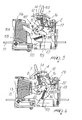
- the circuit breaker is provided with a mechanism for actuating the circuit breaker 107, which allows the movable contacts 104, during the closure of the circuit, to move gradually toward the fixed contacts 105 up to a given distance, typically a few millimeters, and then to trip from this position onto the fixed contacts 105, closing the circuit breaker, regardless of the force and speeds applied to the actuation handle 103.
- the handle support 1 is substantially saddle-shaped, with a head portion 5 and two identical lateral portions 6.
- Two slots and two holes are formed in the head portion 5, and the hooks of two release springs 7 engage therein, coupling to a protruding cambered portion, provided between the slots and the holes, which acts as a locator for the springs.
- the release springs 7 are therefore located inside the two lateral portions 6.
- the head portion 5 also has an actuation lug 8, which protrudes downward.
- Each of the two lateral portions 6 has a pivoting protrusion 9, which pivots the handle support 1 to the containment body 101.
- a profiled central tab 10 and the actuation tab 2 complete the structure of each lateral portion 6, so as to protrude toward the inside of the concave region of the handle support 1.
- the actuation tabs 2 act symmetrically, during the closure of the circuit breaker, on the two closure linkages 4, causing the particular closure of the movable contacts 104. In particular, they slidingly make contact with a concave profile 3 formed at one end of each linkage 4 by virtue of a wedge-shaped portion 11, which constitutes a sort of cam.
- the concave profile 3 allows to actuate the mechanism 107 by means of the handle 103, moving it to the end of its stroke, without causing the movable contacts 104 to move closer to the fixed contacts with respect to the minimum-distance position that they have already reached, and simultaneously allows to load an elastic means suitable to close with a snap action the movable contacts 104.
- the mechanism 107 is reset in order to be able to subsequently close the contacts.
- the handle support 1 is turned clockwise about the pivoting protrusions 9, which are pivoted to the containment body 101, by virtue of the actuation handle 103 rigidly coupled thereto.
- the handle support in its motion, abuts by means of the actuation lug 8 with a locator step formed on an opening lever 12, moving it.
- the opening lever 12 which is located inside the concave region of the handle support 1, is substantially crescent-shaped, so as to slide within the slot formed by the two central tabs 10.
- the opening lever 12 has a first end, which is pivoted to the containment body 101 by means of a pivot 13, and a second end, which can oscillate freely.
- the closure linkages 4 are moved by the rotation of the opening lever 12, since they are pivoted laterally thereto by means of a pivot 14 at a first end, while each second end is pivoted to an actuation lever 15 by means of a single traction pivot 16, which acts as a support for the coupling of the hooks of the release springs 7 and is located proximate to the lower arc-like profile of the opening lever 12.
- the combined rotary and translational motion of the closure linkages 4 tensions the release springs 7, since the traction pivot 16 moves away from the head portion 5 of the handle support 1.
- the pivot 16, therefore, due to the reaction of the release springs 7, contrasts the resetting movement and therefore the rotation of the opening lever 12, contrasting the movement of the closure linkages 4.
- the contrast lever 17 is pivoted at a first end by means of the pivot 18 and abuts, with a second end, against a detent 19 of a release lever 20 which acts as a ratchet system for the contrast lever 17, preventing its counterclockwise rotation and the consequent release of the opening lever 12.
- the release lever 20 is responsible for the snap opening of the circuit when circuit anomalies occur, as will become better apparent hereinafter.
- the opening lever 12 remains motionless, as it is locked by the contrast lever 17, and the first end of the closure linkages 4 also remains motionless, while their second end is turned clockwise due to the contact of the actuation tabs 2 of the handle support 1, in rotation, on the concave profile 3 at the second end of the closure linkages 4.
- the traction pivot 16 is moved toward the pivoted end of the opening lever 12, moving slightly below the lower arc-like profile of the opening lever 12, producing a combined rotary and translational motion of the actuation linkages 15, which in turn produce the counterclockwise rotation, by means of a connecting pivot 21, of a support of the movable contacts 22, which is pivoted to the containment body 102 by means of a kinematic actuation pivot.
- connection pivot 21 acts on the support of the movable contacts 22, so as to turn counterclockwise the lever 25 pivoted therein, gradually moving the movable contact 104 toward the fixed contact 105 up to a distance of a few millimeters (approximately 6 mm), as shown in Figure 7.
- the actuation tabs 2 slide along the concave profile 3 of the closure linkages 4 up to the apex of the wedge 11, turning the second end of the closure linkages 4 up to the pivoted end of the opening lever 12.
- the movement induced on the actuation linkages 15 causes the connecting pivot 21 to trace a semicircular path without causing a further rotation of the movable contact lever 25 with respect to the position that it has already reached.
- the contrast lever 17, by turning counterclockwise, frees the oscillating end of the opening lever 12, which therefore cannot contrast the action of the release springs 7, which are activated and pull the traction pivot 16 toward the head portion 5 of the handle support 1.
- the traction pivot causes the counterclockwise rotation of the opening lever 12 and the clockwise rotation, by means of the actuation linkages 15, of the engagement lever 22 which, by means of a protruding profile 30, abuts against a contrast edge of the movable contact lever 25, making it turn clockwise with a snap action, thus opening the circuit.
- the release lever 20 is returned to the initial position of mutual abutment with the contrast lever 17 by means of a contrast spring.
- the release lever can also be actuated when the circuit is open, obviously when the mechanism is reset, in order to check the correct release of the opening lever 12 by means of the test button 113.
- the position of the bimetallic members 28 can be modified by means of an adjustment screw which can be actuated from the front panel of the circuit breaker containment body, varying the position between the thermal actuator 29 and the upper extension of the release lever 20 and adjusting thermal release tripping.
- a horizontal magnetic pusher 32 actuated by the electrical protection device 109 in a per se known manner pushes a magnetic release lever 33 pivoted to the containment body, making it turn counterclockwise, so that a lug 34 thereof abuts against the front of a concave region 35 of the movable contact lever 25, which opens the circuit by being turned clockwise.
- the magnetic pusher 32 moves the movable contact 104 away from the fixed contact 105 by a few millimeters, typically 4-5 millimeters, before the electrical protection member 109 actuates the thermal tripping mechanism 108 described earlier so as to fully open the contacts as described hereinafter.
- the magnetic release lever 33 is returned into position by a contact spring, while the repositioning of the pusher is achieved by means of a magnetic spring loaded during the closure of the magnetic section of the electrical protection device.
- An external portion of the magnetic section is coupled to a movement lever 36, which is pivoted, by a pivot 37, to the containment body, which has a contact end 38 and a protruding step 39.
- the circuit breaker is provided with an adjustment mechanism which allows to position the magnetic section so as to vary the gap of the electrical protection device 109, as shown in Figures 11 and 13, and therefore adjust the tripping threshold thereof, in the manner described above.
- camtype screw 40 which can be actuated by means of a tool that acts on a first arm of an adjustment lever 41 pivoted to the containment body 101, making it turn counterclockwise in an adjustable manner up to a maximum angle.
- a second arm of the adjustment lever 41 acts on the contact end 38 of the movement lever 36, actuating it.
- the magnetic section moved by the movement lever 36, thus varies the gap between a maximum value, substantially at the vertical position of the movement lever, and a minimum value, at the position of maximum inclination of the movement lever 36 allowed by the adjustment lever 41.
- the movement lever 36 places its protruding step 39 practically adjacent to the lower extension of the release lever 20 to allow more prompt actuation.
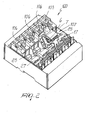
- Each fixed contact 105, with the corresponding electrode 111 and arc quenching chamber, is contained in a containment body 50, which can be removed from the compartment in which it is accommodated inside the circuit breaker.
- the containment body is constituted by a left side wall 51 and by a right side wall 52, which are made of thermosetting plastic material and are coupled along corresponding closure edges and are fastened by rivets 53, so as to constitute a sort of box-like body which has, at the rear, a vertical slot through which the movable contact 104 slides during the opening and closure of the circuit breaker.
- the left side wall 51 has, in a lower region, a seat 54 which accommodates an electrode 111 for the external electrical connections, on the upper end portion of which the pad of the fixed contact 105 is fixed, closing the vertical slot in a lower region.
- a sliding electrode 55 transfers the electric arc to a plurality of arc-like arc quenching blades or laminas 56, arranged in a parallel configuration along guides 57 formed in the inner lateral surfaces of the side walls 51 and 52.
- Both side walls have, at the rear, seats 58 in which magnetic reinforcement blades 59 are inserted; as a whole, the blades surround the fixed contact 105 in order to increase the magnetic field that repels the movable contact with respect to the fixed contact when the circuit breaker is short-circuited, so as to accelerate contact separation even before the electrical protection device trips.
- the circuit breaker has the advantage of achieving a more rapid opening of the contacts in the presence of a short circuit by means of the magnetic reinforcement laminas and of a particular arrangement of the engagement springs.
- a further advantage of the circuit breaker is that it has a closure mechanism that allows to close the contacts with a reduced impact force, so as to make their magnetic repulsion particularly effective when the circuit breaker is closed while a short circuit is already occurring.
- a further advantage of the circuit breaker is that it has a mechanism for adjusting the tripping threshold of the electrical protection device by varying the gap of the magnetic section.
- a further advantage of the circuit breaker is that it has an arc quenching chamber that is monolithic and removable and includes the fixed contact with the corresponding electrode for external connections and magnetic reinforcement laminas.
- the side walls that constitute the arc quenching chamber containment enclosure are made of thermosetting plastics, while the rest of the circuit breaker containment body is made of thermoplastic material.
- the materials used, as well as the dimensions, may of course be any according to requirements and to the state of the art.
Landscapes
- Breakers (AREA)
- Push-Button Switches (AREA)
- Switches With Compound Operations (AREA)
- Thermally Actuated Switches (AREA)
Applications Claiming Priority (2)
| Application Number | Priority Date | Filing Date | Title |
|---|---|---|---|
| IT2001MI001066A ITMI20011066A1 (it) | 2001-05-22 | 2001-05-22 | Interuttore elettrico magnetotermico scatolato |
| ITMI20011066 | 2001-05-22 |
Publications (2)
| Publication Number | Publication Date |
|---|---|
| EP1261008A1 true EP1261008A1 (fr) | 2002-11-27 |
| EP1261008B1 EP1261008B1 (fr) | 2008-04-16 |
Family
ID=11447716
Family Applications (1)
| Application Number | Title | Priority Date | Filing Date |
|---|---|---|---|
| EP02011147A Expired - Lifetime EP1261008B1 (fr) | 2001-05-22 | 2002-05-21 | Disjoncteur magnétothermique enfermé |
Country Status (5)
| Country | Link |
|---|---|
| EP (1) | EP1261008B1 (fr) |
| AT (1) | ATE392706T1 (fr) |
| DE (1) | DE60226096T2 (fr) |
| ES (1) | ES2302772T3 (fr) |
| IT (1) | ITMI20011066A1 (fr) |
Cited By (4)
| Publication number | Priority date | Publication date | Assignee | Title |
|---|---|---|---|---|
| EP1677329A3 (fr) * | 2004-12-30 | 2007-08-15 | ABB Service S.r.l | Appareil électrique avec des contacts fixes, contacts mobiles et chambres de coupure qui peuvent être inspectées |
| CN110233090A (zh) * | 2019-06-18 | 2019-09-13 | 美高电气科技有限公司 | 一种热磁双可调的塑壳断路器 |
| CN112305414A (zh) * | 2020-10-16 | 2021-02-02 | 济南市坤鹏技术开发中心 | 一种特高压真空断路器的分合闸速度测量装置 |
| CN117452210A (zh) * | 2023-12-20 | 2024-01-26 | 中宝电气有限公司 | 一种断路器测试装置及测试方法 |
Citations (6)
| Publication number | Priority date | Publication date | Assignee | Title |
|---|---|---|---|---|
| DE1130036B (de) * | 1960-09-10 | 1962-05-24 | Siemens Ag | Antrieb fuer elektrische Schalter |
| DE1202888B (de) * | 1961-06-27 | 1965-10-14 | Licentia Gmbh | Elektromagnetischer Ausloeser fuer elektrische Selbstschalter |
| US3523261A (en) * | 1967-01-30 | 1970-08-04 | Federal Pacific Electric Co | Current limiting circuit breakers |
| DE4442417C1 (de) * | 1994-11-29 | 1996-02-15 | Kloeckner Moeller Gmbh | Schaltschloß für ein Niederspannungs-Schaltgerät |
| EP0773572A1 (fr) * | 1995-11-08 | 1997-05-14 | Legrand | Appareil électrique à enclenchement brusque |
| EP0977232A2 (fr) * | 1998-07-28 | 2000-02-02 | Eaton Corporation | Compartiment séparé pour conducteur pour disjoncteurs |
-
2001
- 2001-05-22 IT IT2001MI001066A patent/ITMI20011066A1/it unknown
-
2002
- 2002-05-21 DE DE60226096T patent/DE60226096T2/de not_active Expired - Lifetime
- 2002-05-21 EP EP02011147A patent/EP1261008B1/fr not_active Expired - Lifetime
- 2002-05-21 AT AT02011147T patent/ATE392706T1/de not_active IP Right Cessation
- 2002-05-21 ES ES02011147T patent/ES2302772T3/es not_active Expired - Lifetime
Patent Citations (6)
| Publication number | Priority date | Publication date | Assignee | Title |
|---|---|---|---|---|
| DE1130036B (de) * | 1960-09-10 | 1962-05-24 | Siemens Ag | Antrieb fuer elektrische Schalter |
| DE1202888B (de) * | 1961-06-27 | 1965-10-14 | Licentia Gmbh | Elektromagnetischer Ausloeser fuer elektrische Selbstschalter |
| US3523261A (en) * | 1967-01-30 | 1970-08-04 | Federal Pacific Electric Co | Current limiting circuit breakers |
| DE4442417C1 (de) * | 1994-11-29 | 1996-02-15 | Kloeckner Moeller Gmbh | Schaltschloß für ein Niederspannungs-Schaltgerät |
| EP0773572A1 (fr) * | 1995-11-08 | 1997-05-14 | Legrand | Appareil électrique à enclenchement brusque |
| EP0977232A2 (fr) * | 1998-07-28 | 2000-02-02 | Eaton Corporation | Compartiment séparé pour conducteur pour disjoncteurs |
Cited By (8)
| Publication number | Priority date | Publication date | Assignee | Title |
|---|---|---|---|---|
| EP1677329A3 (fr) * | 2004-12-30 | 2007-08-15 | ABB Service S.r.l | Appareil électrique avec des contacts fixes, contacts mobiles et chambres de coupure qui peuvent être inspectées |
| CN1797639B (zh) * | 2004-12-30 | 2010-05-05 | Abb股份公司 | 具有固定触点、移动触点和可检查的弧形腔室的电气装置 |
| CN110233090A (zh) * | 2019-06-18 | 2019-09-13 | 美高电气科技有限公司 | 一种热磁双可调的塑壳断路器 |
| CN110233090B (zh) * | 2019-06-18 | 2024-04-02 | 美高电气科技有限公司 | 一种热磁双可调的塑壳断路器 |
| CN112305414A (zh) * | 2020-10-16 | 2021-02-02 | 济南市坤鹏技术开发中心 | 一种特高压真空断路器的分合闸速度测量装置 |
| CN112305414B (zh) * | 2020-10-16 | 2021-09-17 | 亚太人民集团浙江电力设备有限公司 | 一种特高压真空断路器的分合闸速度测量装置 |
| CN117452210A (zh) * | 2023-12-20 | 2024-01-26 | 中宝电气有限公司 | 一种断路器测试装置及测试方法 |
| CN117452210B (zh) * | 2023-12-20 | 2024-03-26 | 中宝电气有限公司 | 一种断路器测试装置及测试方法 |
Also Published As
| Publication number | Publication date |
|---|---|
| DE60226096D1 (de) | 2008-05-29 |
| ATE392706T1 (de) | 2008-05-15 |
| DE60226096T2 (de) | 2008-11-20 |
| ES2302772T3 (es) | 2008-08-01 |
| ITMI20011066A0 (it) | 2001-05-22 |
| ITMI20011066A1 (it) | 2002-11-22 |
| EP1261008B1 (fr) | 2008-04-16 |
Similar Documents
| Publication | Publication Date | Title |
|---|---|---|
| US5245302A (en) | Automatic miniature circuit breaker with Z-axis assemblable trip mechanism | |
| US5250918A (en) | Automatic miniature circuit breaker with Z-axis assemblage current response mechanism | |
| US5302787A (en) | Automatic miniature circuit breaker with Z-axis assemblable contact assembly | |
| JPS5931817B2 (ja) | 遮断器 | |
| JPH0143975B2 (fr) | ||
| CA1114867A (fr) | Disjoncteur a rupture rapide | |
| US4987395A (en) | Circuit breaker alarm-switch operating apparatus | |
| US3523261A (en) | Current limiting circuit breakers | |
| EP1261008B1 (fr) | Disjoncteur magnétothermique enfermé | |
| EP0150920B1 (fr) | Disjoncteur | |
| US5430419A (en) | Double break circuit breaker having improved secondary section | |
| US5680081A (en) | Circuit breaker having double break mechanism | |
| US3315054A (en) | Overload relay with snap-acting condition responsive switch | |
| US4912441A (en) | Drive mechanism for circuit breaker | |
| US4163881A (en) | Circuit breaker with thrust transmitting spring | |
| US4149129A (en) | Contact control assembly for a circuit breaker | |
| US4764746A (en) | Circuit breaker | |
| EP1178509A2 (fr) | Disjoncteur magnéto-thermique | |
| CA1078437A (fr) | Relais bimetallique de surcharge | |
| US3832663A (en) | Circuit breaker with improved frame and cradle support means | |
| EP0986083B1 (fr) | Disjoncteur magnéto-thermique | |
| JP2567003B2 (ja) | 回路遮断器 | |
| EP1054424B1 (fr) | Appareil électrique modulaire auxiliaire, notamment pour un disjoncteur ou similaire | |
| USRE31690E (en) | Snap action circuit breaker |
Legal Events
| Date | Code | Title | Description |
|---|---|---|---|
| PUAI | Public reference made under article 153(3) epc to a published international application that has entered the european phase |
Free format text: ORIGINAL CODE: 0009012 |
|
| AK | Designated contracting states |
Kind code of ref document: A1 Designated state(s): AT BE CH CY DE DK ES FI FR GB GR IE IT LI LU MC NL PT SE TR |
|
| AX | Request for extension of the european patent |
Free format text: AL;LT;LV;MK;RO;SI |
|
| 17P | Request for examination filed |
Effective date: 20030402 |
|
| AKX | Designation fees paid |
Designated state(s): AT BE CH CY DE DK ES FI FR GB GR IE IT LI LU MC NL PT SE TR |
|
| 17Q | First examination report despatched |
Effective date: 20070412 |
|
| GRAP | Despatch of communication of intention to grant a patent |
Free format text: ORIGINAL CODE: EPIDOSNIGR1 |
|
| GRAS | Grant fee paid |
Free format text: ORIGINAL CODE: EPIDOSNIGR3 |
|
| GRAA | (expected) grant |
Free format text: ORIGINAL CODE: 0009210 |
|
| AK | Designated contracting states |
Kind code of ref document: B1 Designated state(s): AT BE CH CY DE DK ES FI FR GB GR IE IT LI LU MC NL PT SE TR |
|
| REG | Reference to a national code |
Ref country code: CH Ref legal event code: EP |
|
| REG | Reference to a national code |
Ref country code: IE Ref legal event code: FG4D |
|
| REF | Corresponds to: |
Ref document number: 60226096 Country of ref document: DE Date of ref document: 20080529 Kind code of ref document: P |
|
| REG | Reference to a national code |
Ref country code: ES Ref legal event code: FG2A Ref document number: 2302772 Country of ref document: ES Kind code of ref document: T3 |
|
| NLV1 | Nl: lapsed or annulled due to failure to fulfill the requirements of art. 29p and 29m of the patents act | ||
| PG25 | Lapsed in a contracting state [announced via postgrant information from national office to epo] |
Ref country code: PT Free format text: LAPSE BECAUSE OF FAILURE TO SUBMIT A TRANSLATION OF THE DESCRIPTION OR TO PAY THE FEE WITHIN THE PRESCRIBED TIME-LIMIT Effective date: 20080916 Ref country code: NL Free format text: LAPSE BECAUSE OF FAILURE TO SUBMIT A TRANSLATION OF THE DESCRIPTION OR TO PAY THE FEE WITHIN THE PRESCRIBED TIME-LIMIT Effective date: 20080416 Ref country code: FI Free format text: LAPSE BECAUSE OF FAILURE TO SUBMIT A TRANSLATION OF THE DESCRIPTION OR TO PAY THE FEE WITHIN THE PRESCRIBED TIME-LIMIT Effective date: 20080416 |
|
| PG25 | Lapsed in a contracting state [announced via postgrant information from national office to epo] |
Ref country code: AT Free format text: LAPSE BECAUSE OF FAILURE TO SUBMIT A TRANSLATION OF THE DESCRIPTION OR TO PAY THE FEE WITHIN THE PRESCRIBED TIME-LIMIT Effective date: 20080416 |
|
| PG25 | Lapsed in a contracting state [announced via postgrant information from national office to epo] |
Ref country code: MC Free format text: LAPSE BECAUSE OF NON-PAYMENT OF DUE FEES Effective date: 20080531 |
|
| REG | Reference to a national code |
Ref country code: CH Ref legal event code: PL |
|
| ET | Fr: translation filed | ||
| PG25 | Lapsed in a contracting state [announced via postgrant information from national office to epo] |
Ref country code: SE Free format text: LAPSE BECAUSE OF FAILURE TO SUBMIT A TRANSLATION OF THE DESCRIPTION OR TO PAY THE FEE WITHIN THE PRESCRIBED TIME-LIMIT Effective date: 20080716 Ref country code: LI Free format text: LAPSE BECAUSE OF NON-PAYMENT OF DUE FEES Effective date: 20080531 Ref country code: DK Free format text: LAPSE BECAUSE OF FAILURE TO SUBMIT A TRANSLATION OF THE DESCRIPTION OR TO PAY THE FEE WITHIN THE PRESCRIBED TIME-LIMIT Effective date: 20080416 Ref country code: CH Free format text: LAPSE BECAUSE OF NON-PAYMENT OF DUE FEES Effective date: 20080531 |
|
| PLBE | No opposition filed within time limit |
Free format text: ORIGINAL CODE: 0009261 |
|
| STAA | Information on the status of an ep patent application or granted ep patent |
Free format text: STATUS: NO OPPOSITION FILED WITHIN TIME LIMIT |
|
| PG25 | Lapsed in a contracting state [announced via postgrant information from national office to epo] |
Ref country code: BE Free format text: LAPSE BECAUSE OF FAILURE TO SUBMIT A TRANSLATION OF THE DESCRIPTION OR TO PAY THE FEE WITHIN THE PRESCRIBED TIME-LIMIT Effective date: 20080416 |
|
| 26N | No opposition filed |
Effective date: 20090119 |
|
| PG25 | Lapsed in a contracting state [announced via postgrant information from national office to epo] |
Ref country code: IE Free format text: LAPSE BECAUSE OF NON-PAYMENT OF DUE FEES Effective date: 20080521 |
|
| PG25 | Lapsed in a contracting state [announced via postgrant information from national office to epo] |
Ref country code: CY Free format text: LAPSE BECAUSE OF FAILURE TO SUBMIT A TRANSLATION OF THE DESCRIPTION OR TO PAY THE FEE WITHIN THE PRESCRIBED TIME-LIMIT Effective date: 20080416 |
|
| PG25 | Lapsed in a contracting state [announced via postgrant information from national office to epo] |
Ref country code: LU Free format text: LAPSE BECAUSE OF NON-PAYMENT OF DUE FEES Effective date: 20080521 |
|
| PG25 | Lapsed in a contracting state [announced via postgrant information from national office to epo] |
Ref country code: TR Free format text: LAPSE BECAUSE OF FAILURE TO SUBMIT A TRANSLATION OF THE DESCRIPTION OR TO PAY THE FEE WITHIN THE PRESCRIBED TIME-LIMIT Effective date: 20080416 |
|
| PG25 | Lapsed in a contracting state [announced via postgrant information from national office to epo] |
Ref country code: GR Free format text: LAPSE BECAUSE OF FAILURE TO SUBMIT A TRANSLATION OF THE DESCRIPTION OR TO PAY THE FEE WITHIN THE PRESCRIBED TIME-LIMIT Effective date: 20080717 |
|
| REG | Reference to a national code |
Ref country code: FR Ref legal event code: PLFP Year of fee payment: 15 |
|
| REG | Reference to a national code |
Ref country code: FR Ref legal event code: PLFP Year of fee payment: 16 |
|
| REG | Reference to a national code |
Ref country code: FR Ref legal event code: PLFP Year of fee payment: 17 |
|
| PGFP | Annual fee paid to national office [announced via postgrant information from national office to epo] |
Ref country code: DE Payment date: 20210527 Year of fee payment: 20 Ref country code: FR Payment date: 20210525 Year of fee payment: 20 Ref country code: IT Payment date: 20210524 Year of fee payment: 20 |
|
| PGFP | Annual fee paid to national office [announced via postgrant information from national office to epo] |
Ref country code: ES Payment date: 20210601 Year of fee payment: 20 Ref country code: GB Payment date: 20210527 Year of fee payment: 20 |
|
| REG | Reference to a national code |
Ref country code: DE Ref legal event code: R071 Ref document number: 60226096 Country of ref document: DE |
|
| REG | Reference to a national code |
Ref country code: GB Ref legal event code: PE20 Expiry date: 20220520 |
|
| PG25 | Lapsed in a contracting state [announced via postgrant information from national office to epo] |
Ref country code: GB Free format text: LAPSE BECAUSE OF EXPIRATION OF PROTECTION Effective date: 20220520 |
|
| REG | Reference to a national code |
Ref country code: ES Ref legal event code: FD2A Effective date: 20220830 |
|
| PG25 | Lapsed in a contracting state [announced via postgrant information from national office to epo] |
Ref country code: ES Free format text: LAPSE BECAUSE OF EXPIRATION OF PROTECTION Effective date: 20220522 |