EP1261104A2 - Machine électrique tournante du type à aimants permanents - Google Patents
Machine électrique tournante du type à aimants permanents Download PDFInfo
- Publication number
- EP1261104A2 EP1261104A2 EP02010187A EP02010187A EP1261104A2 EP 1261104 A2 EP1261104 A2 EP 1261104A2 EP 02010187 A EP02010187 A EP 02010187A EP 02010187 A EP02010187 A EP 02010187A EP 1261104 A2 EP1261104 A2 EP 1261104A2
- Authority
- EP
- European Patent Office
- Prior art keywords
- permanent magnet
- rotor core
- electrical machine
- rotating electrical
- type rotating
- Prior art date
- Legal status (The legal status is an assumption and is not a legal conclusion. Google has not performed a legal analysis and makes no representation as to the accuracy of the status listed.)
- Withdrawn
Links
- 230000004907 flux Effects 0.000 claims abstract description 73
- 230000004888 barrier function Effects 0.000 claims abstract description 34
- 238000003780 insertion Methods 0.000 claims description 35
- 230000037431 insertion Effects 0.000 claims description 35
- 230000002093 peripheral effect Effects 0.000 claims description 4
- 239000000126 substance Substances 0.000 claims description 2
- BGPVFRJUHWVFKM-UHFFFAOYSA-N N1=C2C=CC=CC2=[N+]([O-])C1(CC1)CCC21N=C1C=CC=CC1=[N+]2[O-] Chemical compound N1=C2C=CC=CC2=[N+]([O-])C1(CC1)CCC21N=C1C=CC=CC1=[N+]2[O-] BGPVFRJUHWVFKM-UHFFFAOYSA-N 0.000 description 14
- 230000000694 effects Effects 0.000 description 9
- 230000008859 change Effects 0.000 description 8
- 230000009977 dual effect Effects 0.000 description 5
- 238000004804 winding Methods 0.000 description 5
- 238000010586 diagram Methods 0.000 description 4
- 238000009826 distribution Methods 0.000 description 4
- 238000004519 manufacturing process Methods 0.000 description 4
- 238000009499 grossing Methods 0.000 description 3
- 229920006395 saturated elastomer Polymers 0.000 description 3
- 230000008901 benefit Effects 0.000 description 2
- 239000003990 capacitor Substances 0.000 description 2
- 238000007710 freezing Methods 0.000 description 2
- 230000008014 freezing Effects 0.000 description 2
- 238000003475 lamination Methods 0.000 description 2
- 238000000034 method Methods 0.000 description 2
- 238000005057 refrigeration Methods 0.000 description 2
- 230000001360 synchronised effect Effects 0.000 description 2
- RYGMFSIKBFXOCR-UHFFFAOYSA-N Copper Chemical compound [Cu] RYGMFSIKBFXOCR-UHFFFAOYSA-N 0.000 description 1
- 238000001816 cooling Methods 0.000 description 1
- 229910052802 copper Inorganic materials 0.000 description 1
- 239000010949 copper Substances 0.000 description 1
- 238000005520 cutting process Methods 0.000 description 1
- 229910052761 rare earth metal Inorganic materials 0.000 description 1
- 150000002910 rare earth metals Chemical class 0.000 description 1
- 238000004064 recycling Methods 0.000 description 1
- 239000003507 refrigerant Substances 0.000 description 1
- 230000004044 response Effects 0.000 description 1
- 238000010792 warming Methods 0.000 description 1
Images


Classifications
-
- H—ELECTRICITY
- H02—GENERATION; CONVERSION OR DISTRIBUTION OF ELECTRIC POWER
- H02K—DYNAMO-ELECTRIC MACHINES
- H02K21/00—Synchronous motors having permanent magnets; Synchronous generators having permanent magnets
- H02K21/12—Synchronous motors having permanent magnets; Synchronous generators having permanent magnets with stationary armatures and rotating magnets
- H02K21/14—Synchronous motors having permanent magnets; Synchronous generators having permanent magnets with stationary armatures and rotating magnets with magnets rotating within the armatures
-
- H—ELECTRICITY
- H02—GENERATION; CONVERSION OR DISTRIBUTION OF ELECTRIC POWER
- H02K—DYNAMO-ELECTRIC MACHINES
- H02K1/00—Details of the magnetic circuit
- H02K1/06—Details of the magnetic circuit characterised by the shape, form or construction
- H02K1/22—Rotating parts of the magnetic circuit
- H02K1/27—Rotor cores with permanent magnets
- H02K1/2706—Inner rotors
- H02K1/272—Inner rotors the magnetisation axis of the magnets being perpendicular to the rotor axis
- H02K1/274—Inner rotors the magnetisation axis of the magnets being perpendicular to the rotor axis the rotor consisting of two or more circumferentially positioned magnets
- H02K1/2753—Inner rotors the magnetisation axis of the magnets being perpendicular to the rotor axis the rotor consisting of two or more circumferentially positioned magnets the rotor consisting of magnets or groups of magnets arranged with alternating polarity
- H02K1/276—Magnets embedded in the magnetic core, e.g. interior permanent magnets [IPM]
- H02K1/2766—Magnets embedded in the magnetic core, e.g. interior permanent magnets [IPM] having a flux concentration effect
Definitions
- the present invention relates to the permanent magnet type rotating electrical machine having a rotor equipped with a permanent magnet for field and, particularly, to the permanent magnet type rotating electrical machine suitable to be mounted on the compressor of an air conditioner.
- the rotor core in a permanent magnet type rotating electrical machine comprises a first core producing only the reluctance torque and a second core for generating at least magnet torque wherein permanent magnets in the number corresponding to the number of poles are embedded along the outer periphery of the core at an equally spaced interval.
- the Japanese application patent laid-open publication No. 2000-37052 discloses a permanent magnet type rotating electrical machine wherein a permanent magnet rotor is located at the center and a reluctance torque rotor is arranged on each of both ends.
- the first object of the present invention is to provide a permanent magnet type rotating electrical machine capable of suppressing the increase of core loss due to armature reaction magnetic flux and making an effective use of reluctance torque.
- the second object of the present invention is to provide a permanent magnet type rotating electrical machine which is mounted on the compressor of the air conditioner and which can be driven by a 180-degree current-applied inverter without magnetic pole position sensor, utilizing the change in reluctance.
- Reluctance torque relates to the magnitude of armature reaction magnetic flux produced by the current supplied to the armature wiring.
- Armature reaction magnetic flux passes through the interpolar core positioned between poles of the permanent magnet of the rotor core.
- the inter-polar core also passes through the magnetic flux from the permanent magnet, so it is placed in the magnetically saturated area so that the armature reaction magnetic flux cannot easily pass through.
- harmonic wave magnetic flux occurs to the magnetic flux created by armature wiring. If harmonic wave magnetic flux created by armature wiring passes through the interpolar core placed in the magnetically saturated area, core loss is increased, with the result that effective use of reluctance torque is interfered.
- One of the characteristics of the present invention is found in the capability of reducing the magnetic flux density of the rotor core where armature reaction magnetic flux passes by, and ensuring that a big reluctance torque is produced with a small amount of current.
- the first rotor core incorporating the permanent magnet is arranged in such a way that a concave portion is provided between poles in the vicinity of the outer surface on the first rotor core, so that the gap length of the magnetic path on the q-axis side is greater than that on the d-axis side.
- the second rotor core as a reluctance torque rotor is provided with an almost true round peripheral shape, without a permanent magnet placed in the permanent magnet insertion hole and without a concave portion formed between poles.
- the arrangement described above ensures that the armature reaction magnetic flux cannot easily pass through the first rotor core with the permanent magnet embedded therein, because of the concave portion provided between poles in the vicinity of the outer surface, whereas armature reaction magnetic flux can pass through the interpolar core of the second rotor core without a permanent magnet placed in the permanent magnet insertion hole and without a concave portion formed between poles. Since the interpolar core of the second rotor core is not equipped with a permanent magnet, its magnetic flux density is low, and a big armature reaction magnetic flux is produced by a small amount of armature current. This results in a small core loss due to armature reaction magnetic flux. This makes it possible to provide a permanent magnet type rotating electrical machine capable of improving output by an effective use of reluctance torque.
- the permanent magnet type rotating electrical machine can be driven by a 180-degree current-applied sinusoidal wave inverter without magnetic pole position sensor.
- Changes in reactance on the first rotor core side are reduced since concave portions are provided on the interpolar core of the first rotor core where the permanent magnet is inserted. Changes in reactance with respect to rotor position depend on the changes in reactance on the second rotor core side because flux barriers are provided on the second rotor core. Reactance with respect to rotor position on the second rotor core side changes almost in the form of a sinusoidal wave. This makes it possible to evaluate magnetic pole position by observing the reactance value, hence, to provide a permanent magnet type rotating electrical machine which can be driven by a 180-degree current-applied inverter without magnetic pole position sensor.
- a further characteristic of the present invention is found in that the width of the permanent magnet insertion hole on the first rotor core is designed greater than that of the flux barrier provided on said second rotor core, or the permanent magnet insertion hole provided on the first rotor core is different from that of the flux barrier provided on the second rotor core.
- a further characteristic of the present invention is found in that the number of permanent magnet insertion holes on the second rotor core greater than that of the permanent magnet insertion holes provided on the first rotor core to ensure easy passage of armature reaction magnetic flux, thereby allowing reluctance torque to be increased.
- a still further characteristic of the present invention is found in that the permanent magnet insertion hole and flux barrier installed on the first and second rotor core are formed in a straight line or shaped like a letter U or V.
- a preferred embodiment of the present invention is that the permanent magnet insertion hole of the first rotor core and the flux barrier on the second rotor core have identically the same shape. This has an effect of increasing the mass production efficiency of core sheets for the first and second rotor cores formed by lamination of core sheets.
- Fig. 1 is a perspective view representing a rotor configuration as the first embodiment of a permanent magnet type rotating electrical machine according to the present invention.
- Fig. 2 is a cross sectional view in the radial direction representing the rotor core configuration given in Fig. 1.
- a rotor 10 comprises a first rotor core 1 and the second rotor core 2.
- the first rotor core 1 comprises a rare earth permanent magnet 4 (four-pole type is shown here) arranged in the convex V-shaped permanent magnet insertion hole 3 with respect to the shaft of the rotor 10, an interpolar core 5, a rotor shaft hole 6 for being fitted to the shaft (not illustrated) and a river hole 7 for securing the first rotor core 1.
- the second rotor core 2 comprises a flux barrier (hole) 8 having identically the same shape as that of the permanent magnet insertion hole 3, namely, the convex V-shaped flux barrier (hole) 8 with respect to the shaft of rotor 10, as well as a rotor shaft hole 9 for being fitted to the shaft (not illustrated), and a river hole 11 for securing the second rotor core.
- a flux barrier (hole) 8 having identically the same shape as that of the permanent magnet insertion hole 3, namely, the convex V-shaped flux barrier (hole) 8 with respect to the shaft of rotor 10, as well as a rotor shaft hole 9 for being fitted to the shaft (not illustrated), and a river hole 11 for securing the second rotor core.
- first and second rotor cores The difference between the first and second rotor cores is that a permanent magnet 4 is inserted in the permanent magnet insertion hole 3 of the first rotor core 1, whereas a permanent magnet is not inserted in the flux barrier (hole) 8 of the second rotor core 2. Moreover, they have difference shapes in the vicinity of the outer surface of the core, as will be explained below.
- a V-shaped permanent magnet 4 is inserted in the permanent magnet insertion hole 3 of the first rotor core 1, and the central direction of this letter V is referred to as d-axis, which serves as a magnetic flux axis.
- the magnetic flux axis 90 degrees different from this d-axis in terms of electric angle is referred to as q-axis, which serves as an armature reaction axis.
- a concave portion 12 is formed by slightly cutting the interpolar core 5 in a letter V in the vicinity of the rotor surface on the q-axis side.
- the concave portion is not formed on the interpolar core 13 of the second rotor core 2; therefore, the outer periphery of the second rotor core 2 is truly round, with the result that the armature reaction magnetic flux can easily pass through the core between poles 13 of the second rotor core 2. This will be explained in greater details using Fig. 3.
- Fig. 3 is a cross sectional view in the radial direction representing a first rotor core 1 as the first embodiment of the permanent magnet type rotating electrical machine according to the present invention.
- Fig. 4 is a cross sectional view in the radial direction representing a first rotor core 2 as the first embodiment of the permanent magnet type rotating electrical machine according to the present invention.
- the stators 14 are the same, and multiple tees 16 and slots 17 are provided in the stator core 15.
- Armature wiring 18 in a concentrated winding is provided in the slot 17 so as to surround the tees 16; namely, U-phase winding 18U, V-phase winding 18V and W-phase winding 18W are provided in a concentrated winding.
- the permanent magnet insertion hole 3 of in the first rotor core 1 is made in identically the same form as the flux barrier (hole) 8 of the second rotor core 2. This has an effect of increasing the mass production efficiency of core sheets for the first and second rotor cores formed by lamination of core sheets.
- Fig. 5 is a cross sectional view in the radial direction representing the rotor core configuration as the second embodiment of the permanent magnet type rotating electrical machine according to the present invention.
- the same components as those in Fig. 2 will be assigned with the same numerals to avoid redundant explanation.
- the difference from Fig. 2 is that the width of the flux barrier (hole) 8 of the second rotor core 2 is smaller.
- the width of flux barrier (hole) 8 is reduced so that the permanent magnet 4 will not enter the second rotor core 2 when the permanent magnet 4 is inserted in the axial direction of the first rotor core 1. Then the permanent magnet 4 is positioned. This has the effect of reducing the number of production processes -- another advantage in addition to the basic performance described in the first Embodiment.
- Fig. 6 is a cross sectional view in the radial direction representing the rotor core configuration as the third embodiment of the permanent magnet type rotating electrical machine according to the present invention.
- the same components as those in Fig. 2 will be assigned with the same numerals to avoid redundant explanation.
- the difference from Fig. 2 is that the position of the flux barrier (hole) 82 of the second rotor core 2 is shifted toward the outer surface.
- the position of the flux barrier (hole) 8 is shifted so that the permanent magnet 4 will not enter the second rotor core 2 when the permanent magnet 4 is inserted in the axial direction of the first rotor core 1. Then the permanent magnet 4 is positioned. This has the effect of reducing the number of production processes - - another advantage in addition to the basic performance described in the first embodiment.
- Fig. 7 is a cross sectional view in the radial direction representing the rotor core configuration as the fourth embodiment of the permanent magnet type rotating electrical machine according to the present invention.
- the same components as those in Fig. 2 will be assigned with the same numerals to avoid redundant explanation.
- the difference from Fig. 2 is that the flux barrier (hole) 8 of the second rotor core 2 is divided into two flux barriers (hole) 83 and 84 in order to ensure easy passage of armature reaction magnetic flux. This provides the same basic performance as that of the first embodiment, and will increase reluctance torque.
- Fig. 8 is a cross sectional view in the radial direction representing the rotor core configuration as the fifth embodiment of the permanent magnet type rotating electrical machine according to the present invention.
- the same components as those in Fig. 2 will be assigned with the same numerals to avoid redundant explanation.
- the difference of Fig. 8 from Fig. 2 is that the first rotor core 1 is formed by inserting a permanent magnet 41 made of one flat plate into the permanent magnet insertion hole 31 of a straight line (linear form).
- the shape of the flux barrier (hole)85 of the second rotor core 2 is also changed. This has the effect of providing the basic performance described in the first embodiment.
- Fig. 9 is a cross sectional view in the radial direction representing the rotor core configuration as the sixth embodiment of permanent magnet type rotating electrical machine according to the present invention.
- the same components as those in Fig. 2 will be assigned with the same numerals to avoid redundant explanation.
- the difference from Fig. 2 is that the permanent magnet insertion hole 32, permanent magnet 42 in the first rotor core 1 and the flux barrier (hole) 86 of the second rotor core 2 are formed like a letter U (an arched form).
- Fig. 10 is a cross sectional view in the radial direction representing the rotor core configuration as the seventh embodiment of the permanent magnet type rotating electrical machine according to the present invention.
- the same components as those in Figs. 1 and 2 will be assigned with the same numerals to avoid redundant explanation.
- the difference of Fig. 10 from Figs. 1 and 2 is that balance weights 19 and 20 are on the first rotor core 1 and the second rotor core 2 respectively, and the flux barrier (hole) 8 is filled with the balance weight 20 of non-magnetic substance on the second rotor core 2 side.
- the permanent magnet 4 can be positioned so that the permanent magnet 4 will not enter the second rotor core 2 when the permanent magnet 4 is inserted in the axial direction of the first rotor core 1.
- Rivets 21 are provided to fix the first rotor core 1 and the second rotor core 2 in position.
- the present embodiment provides the same basic performance described in the first embodiment.
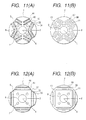
- Fig. 11 is a cross sectional view in the radial direction representing the rotor core configuration as the eighth embodiment of the permanent magnet type rotating electrical machine according to the present invention.
- the same components as those in Fig. 2 will be assigned with the same numerals to avoid redundant explanation.
- the difference from Fig. 2 is that the flux barriers (holes) 86 and 87 of the second rotor core 2 are arranged to form a dual V-shape in order to ensure easy passage of armature reaction magnetic flux.
- permanent magnet insertion holes 33 and 34 in the first rotor core 1 are also formed in a dual V-shape. Permanent magnets 43 and 44 are also inserted in them. This will provide the same basic performance as that of the first embodiment, and will increase reluctance torque in the second rotor core 2.
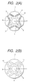
- Fig. 12 is a cross sectional view in the radial direction representing the rotor core configuration as the nine embodiment permanent magnet type rotating electrical machine according to the present invention.
- the same components as those in Fig. 2 will be assigned with the same numerals to avoid redundant explanation.
- the difference from Fig. 2 is that permanent magnets 45 and 46 are inserted in the permanent magnet insertion holes 35 and 36 on the first rotor core 1, and permanent magnets 45 and 46 are configured in a dual structure.
- the shape of flux barriers (holes) 88 and 89 of the second rotor core 2 is also changed. This will provide the same basic performance as that of the first embodiment.
- Fig. 13 is across sectional view in the radial direction representing the rotor core configuration as the tenth embodiment of permanent magnet type rotating electrical machine according to the present invention.
- the difference from Fig. 2 is that permanent magnet insertion holes 37 and 38 of a dual U-shape structure are used as the permanent magnet insertion hole 3 of the first rotor core 1. Permanent magnets 47 and 48 are inserted in them.
- the flux barrier (hole) 8 of the second rotor core 2 is also changed into flux barriers (holes) 801 and 802 of dual U-shaped (arched) structure. This will provide the same basic performance as that of the first embodiment, and will increase reluctance torque in the second rotor core 2.
- Fig. 14 is a block diagram representing the refrigeration cycle of an air conditioner as the eleventh embodiment according to the present invention.
- Numeral 60 denotes an outdoor apparatus, 61 an indoor apparatus and 62 a compressor.
- the permanent magnet type rotating electrical machine 63 and compressor 64 are sealed in the compressor 62.
- Numeral 65 denotes a condenser, 66 an expansion valve, and 67 an evaporator.
- the refrigerant is circulated in the direction of an arrow and is compressed by the compressor 62.
- heat exchange is performed between an outdoor apparatus 60 consisting of a condenser 65 and expansion valve 66, and an indoor apparatus 61 consisting of an evaporator 67, whereby cooling function is performed.
- the permanent magnet type rotating electrical machine shown in the embodiments given above will be used as permanent magnet type rotating electrical machine 63. This will improve the output of the permanent magnet type rotating electrical machine 63 and will reduce the air conditioner input. So it has the effect of reducing the emission of CO2 which may cause global warming. It goes without saying that the same effect can be obtained when used in the compressor of the refrigerator and freezer.
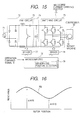
- Fig. 15 is a diagram representing a permanent magnet type motor drive system by a 180-degree current-carrying inverter drive system as the twelfth embodiment according to the present invention.
- Numeral 70 denotes a 180-degree current-applied inverter, 71 a single-phase a. c. power supply, 72 a rectifying and smoothing circuit, 73 a PAM circuit, 74 a smoothing capacitor, 75 a switching circuit, 76 a driver for switching circuit 75, 77 a driver for PAM circuit 73, 78 a microcomputer, 79 a sensor-less position detector of software configuration, and 62 a compressor.
- a permanent magnet type rotating electrical machine 63 described in embodiments described above is enclosed in this compressor 62.
- Symbol S denotes an operation command signal.
- Fig. 16 is a drawing representing the reactance distribution RB of the permanent magnet type rotating electrical machine according to the present invention as an embodiment of the present invention.
- d-axis is assumed as representing the direction of magnetic flux of the permanent magnet
- q-axis as representing the axis which intersects it at a right angle
- the magnetic pole position d-axis is evaluated from the induced voltage of the permanent magnet type rotating electrical machine 63 by the position detector 79 without sensor based on the reactance distribution of the rotor.
- the permanent magnet type rotating electrical machine 63 can be accelerated as a synchronous motor.
- the PAM circuit 73 is actuated to increase the d. c. voltage of the smoothing capacitor 74.
- an inverter drive method is used to driver the compressors of the air conditioner, refrigerator and freezing in order to save energy.
- the magnetic pole position of the permanent magnet of the rotor must be detected.
- the temperature in the compressor 62 exceeds 100 degrees Celsius, so a magnetic pole position sensor such as Hall IC cannot be used.
- magnetic pole position can be detected from the induced voltage when the current at an electric angle of 60 degrees is not running. However, this is not possible when a 180-degree current-applied inverter is use for driving.
- the permanent magnet type rotating electrical machine is driven by the 180-degree current-applied inverter, magnetic pole position must be detected from the change in reactance. In this case, mere change of reactance is not sufficient. To detect any magnetic pole position, the waveform must be ever-changing sinusoidal waveform or triangular waveform.
- a concave portion is provided on the interpolar core 5 of the first rotor core 1 where permanent magnet 4 is inserted to reduce the change in reluctance on the rotor core 1 side.
- a flux barrier (hole) 8 is provided on the second rotor core 2, so the change in reactance with respect to rotor position depends on the change in reactance on the second rotor core 2 side, and reactance with respect to rotor position on the second rotor core 2 side changes in almost sinusoidal waveform. Accordingly, magnetic pole position can be determined by detecting the reactance during stop.
- a permanent magnet type rotating electrical machine 63 can be driven a 180-degree current-applied inverter without magnetic pole position sensor.
- the output can be improved and torque ripple during commutation can be reduced, whereby noise is minimized, if the permanent magnet type rotating electrical machine is driven by a 180-degree current-applied inverter.
- the passage of armature reaction magnetic flux is made difficult by increasing the length of the gap on the q-axis side of the first rotor core 1 provided with a permanent magnet, whereas the passage of armature reaction magnetic flux is made easy by reducing the length of the gap on the q-axis side of the second rotor core 2 without a permanent magnet.
- This makes it possible to generate a large armature reaction magnetic flux with a small amount of armature current.
- a permanent magnet type rotating electrical machine capable of delivering a large output can be provided by making an effective use of reluctance torque.
- the second rotor core 2 is provided with flux barriers, so the change in reactance with respect to rotor position depends on the change in reactance on the second rotor core 2 side, and reactance with respect to rotor position changes in almost sinusoidal waveform. Accordingly, a permanent magnet type rotating electrical machine can be driven by a 180-degree current-applied inverter without magnetic pole position sensor. As a result, the output can be improved and torque ripple during commutation can be reduced, whereby noise is minimized when compared with the case where a 120-degree current-applied inverter is used for driving.
- a permanent magnet type rotating electrical machine capable of delivering a large output can be provided by making an effective use of reluctance torque.
- the permanent magnet type rotating electrical machine can be driven by a 180-degree current-applied inverter without magnetic pole position sensor.
- the output can be improved and noise can be minimized when compared with the case where a 120-degree current-applied inverter is used for driving.
Landscapes
- Engineering & Computer Science (AREA)
- Power Engineering (AREA)
- Permanent Field Magnets Of Synchronous Machinery (AREA)
- Iron Core Of Rotating Electric Machines (AREA)
- Synchronous Machinery (AREA)
- Permanent Magnet Type Synchronous Machine (AREA)
Applications Claiming Priority (2)
| Application Number | Priority Date | Filing Date | Title |
|---|---|---|---|
| JP2001156327A JP2002354730A (ja) | 2001-05-25 | 2001-05-25 | 永久磁石式回転電機 |
| JP2001156327 | 2001-05-25 |
Publications (1)
| Publication Number | Publication Date |
|---|---|
| EP1261104A2 true EP1261104A2 (fr) | 2002-11-27 |
Family
ID=19000350
Family Applications (1)
| Application Number | Title | Priority Date | Filing Date |
|---|---|---|---|
| EP02010187A Withdrawn EP1261104A2 (fr) | 2001-05-25 | 2002-05-14 | Machine électrique tournante du type à aimants permanents |
Country Status (6)
| Country | Link |
|---|---|
| US (1) | US20020175584A1 (fr) |
| EP (1) | EP1261104A2 (fr) |
| JP (1) | JP2002354730A (fr) |
| KR (1) | KR20020090342A (fr) |
| CN (1) | CN1388624A (fr) |
| TW (1) | TW565981B (fr) |
Cited By (6)
| Publication number | Priority date | Publication date | Assignee | Title |
|---|---|---|---|---|
| WO2005086317A1 (fr) * | 2004-03-09 | 2005-09-15 | Rotatek Finland Oy | Rotor pour machine a aimants permanents |
| EP1505718A4 (fr) * | 2003-03-17 | 2013-04-10 | Panasonic Corp | Compresseur a alimentation electrique |
| EP2693605A4 (fr) * | 2011-03-31 | 2016-03-23 | Daikin Ind Ltd | Rotor et mécanisme électrique tournant utilisant ce rotor |
| EP2741400B1 (fr) | 2011-08-05 | 2018-02-21 | Gree Electric Appliances, Inc. of Zhuhai | Rotor de moteur et moteur comportant ce rotor |
| EP3780350A1 (fr) * | 2019-08-14 | 2021-02-17 | Secop GmbH | Rotor à aimant permanent intérieur pour un compresseur de réfrigérant |
| CN114552927A (zh) * | 2022-03-22 | 2022-05-27 | 哈尔滨理工大学 | 一种紧凑双转子环形绕组永磁轮毂电机 |
Families Citing this family (38)
| Publication number | Priority date | Publication date | Assignee | Title |
|---|---|---|---|---|
| CN1297059C (zh) * | 2003-06-30 | 2007-01-24 | 哈尔滨工业大学 | 直接驱动永磁式磁阻电机 |
| JP4607472B2 (ja) * | 2004-02-03 | 2011-01-05 | 三菱電機株式会社 | 永久磁石型回転機の回転子及びそれを備えた永久磁石型回転機 |
| KR100524544B1 (ko) * | 2004-07-20 | 2005-10-31 | 삼성광주전자 주식회사 | 회전자 및 이를 갖춘 압축기 |
| JP4815204B2 (ja) * | 2005-12-01 | 2011-11-16 | アイチエレック株式会社 | 永久磁石回転機及び圧縮機 |
| CN100369358C (zh) * | 2006-03-30 | 2008-02-13 | 上海大学 | 表面式概念永磁电机的内置式转子 |
| TWI348258B (en) * | 2006-11-10 | 2011-09-01 | Ind Tech Res Inst | A motor mechanism of dc frequency conversion of compressor |
| JP5157138B2 (ja) * | 2006-11-24 | 2013-03-06 | 株式会社日立製作所 | 永久磁石式回転電機及び風力発電システム |
| KR101341625B1 (ko) * | 2007-05-31 | 2013-12-20 | 엘지전자 주식회사 | 동기 리럭턴스 모터 |
| US7626309B2 (en) * | 2007-09-12 | 2009-12-01 | Canopy Technologies, Llc | Method of balancing an embedded permanent magnet motor rotor |
| US20090224624A1 (en) * | 2008-03-06 | 2009-09-10 | Ajith Kuttannair Kumar | Rotor structure for interior permanent magnet electromotive machine |
| TWI383563B (zh) * | 2008-11-28 | 2013-01-21 | Ind Tech Res Inst | 應用於壓縮機的線性馬達 |
| JP5278003B2 (ja) * | 2009-01-30 | 2013-09-04 | トヨタ自動車株式会社 | 電動機 |
| AU2010274456B2 (en) * | 2009-07-23 | 2013-10-31 | Daikin Industries, Ltd. | Rotor |
| JP4821902B2 (ja) * | 2009-09-30 | 2011-11-24 | ダイキン工業株式会社 | モータ及びそれを備えたモータ駆動システム |
| JP5643127B2 (ja) * | 2011-02-03 | 2014-12-17 | トヨタ自動車株式会社 | 回転電機用回転子 |
| US9172279B2 (en) * | 2011-02-04 | 2015-10-27 | Mitsubishi Electric Corporation | Automotive embedded permanent magnet rotary electric machine |
| WO2013179375A1 (fr) * | 2012-05-28 | 2013-12-05 | 株式会社日立産機システム | Machine électrique rotative à couple composite |
| JP5732440B2 (ja) * | 2012-08-08 | 2015-06-10 | 日立アプライアンス株式会社 | 洗濯乾燥機および洗濯乾燥機ファン駆動用電動機 |
| FR2995469B1 (fr) | 2012-09-13 | 2017-04-21 | Moteurs Leroy-Somer | Rotor de machine electrique tournante, comportant une masse rotorique dans laquelle sont menages des logements. |
| EP2916434B1 (fr) * | 2012-11-01 | 2017-07-19 | Mitsubishi Electric Corporation | Moteur électrique avec aimant permanent encastré, compresseur et équipement de réfrigération et de climatisation |
| JP2014150695A (ja) * | 2013-02-04 | 2014-08-21 | Toshiba Carrier Corp | 永久磁石電動機、密閉型圧縮機および冷凍サイクル装置 |
| CN103280904A (zh) * | 2013-05-03 | 2013-09-04 | 苏州和鑫电气股份有限公司 | 电动汽车用双层v型内置式永磁电机转子 |
| KR20150078467A (ko) * | 2013-12-30 | 2015-07-08 | 현대자동차주식회사 | 매입형 영구자석 모터의 회전자 |
| FR3019947B1 (fr) * | 2014-04-10 | 2017-12-08 | Moteurs Leroy-Somer | Stator de machine electrique tournante. |
| FR3019948B1 (fr) | 2014-04-10 | 2017-12-22 | Moteurs Leroy-Somer | Rotor de machine electrique tournante. |
| JP2017070040A (ja) * | 2015-09-29 | 2017-04-06 | アイシン精機株式会社 | 三相回転電機 |
| JP7059059B2 (ja) * | 2018-03-15 | 2022-04-25 | 本田技研工業株式会社 | 回転電機のロータ |
| JP7059058B2 (ja) * | 2018-03-15 | 2022-04-25 | 本田技研工業株式会社 | 回転電機のロータ |
| CN108988527A (zh) * | 2018-06-27 | 2018-12-11 | 德威(苏州)新能源有限公司 | 一种混合励磁高功率密度磁阻永磁电机转子 |
| CN108736611B (zh) * | 2018-08-09 | 2024-05-24 | 珠海格力节能环保制冷技术研究中心有限公司 | 一种电机转子和电机 |
| CN110971029B (zh) * | 2018-09-28 | 2022-03-01 | 佛山市威灵洗涤电机制造有限公司 | 转子冲片、转子和电机 |
| CN109474094B (zh) * | 2018-11-19 | 2025-01-10 | 珠海凌达压缩机有限公司 | 一种转子结构、包括该转子结构的电机及电器 |
| US11949291B2 (en) * | 2019-02-22 | 2024-04-02 | Mitsubishi Electric Corporation | Motor having rotor with different core regions, compressor, and air conditioner having the motor |
| JP7441736B2 (ja) * | 2020-06-10 | 2024-03-01 | 株式会社マキタ | 電動作業機 |
| US11909264B2 (en) * | 2020-07-14 | 2024-02-20 | Board Of Regents, The University Of Texas System | Rotor configuration for switched reluctance motor with minimized torque ripple |
| CN112737178A (zh) * | 2021-01-06 | 2021-04-30 | 杭州微光技术有限公司 | 一种高速转子及带有该转子的高速驱控一体伺服电机 |
| CN115694014A (zh) * | 2022-11-01 | 2023-02-03 | 浙江极氪智能科技有限公司 | 电机转子铁芯段、及具有其的转子铁芯总成和电机转子 |
| US12573927B2 (en) * | 2023-10-10 | 2026-03-10 | GM Global Technology Operations LLC | Hybrid rotor for synchronous machine |
-
2001
- 2001-05-25 JP JP2001156327A patent/JP2002354730A/ja active Pending
- 2001-10-04 US US09/970,259 patent/US20020175584A1/en not_active Abandoned
-
2002
- 2002-05-02 TW TW091109165A patent/TW565981B/zh active
- 2002-05-14 EP EP02010187A patent/EP1261104A2/fr not_active Withdrawn
- 2002-05-24 KR KR1020020028951A patent/KR20020090342A/ko not_active Withdrawn
- 2002-05-24 CN CN02120666A patent/CN1388624A/zh active Pending
Cited By (8)
| Publication number | Priority date | Publication date | Assignee | Title |
|---|---|---|---|---|
| EP1505718A4 (fr) * | 2003-03-17 | 2013-04-10 | Panasonic Corp | Compresseur a alimentation electrique |
| WO2005086317A1 (fr) * | 2004-03-09 | 2005-09-15 | Rotatek Finland Oy | Rotor pour machine a aimants permanents |
| EP2693605A4 (fr) * | 2011-03-31 | 2016-03-23 | Daikin Ind Ltd | Rotor et mécanisme électrique tournant utilisant ce rotor |
| US9712006B2 (en) | 2011-03-31 | 2017-07-18 | Daikin Industries, Ltd. | Rotor and rotary electric machine using the same |
| EP2741400B1 (fr) | 2011-08-05 | 2018-02-21 | Gree Electric Appliances, Inc. of Zhuhai | Rotor de moteur et moteur comportant ce rotor |
| EP3780350A1 (fr) * | 2019-08-14 | 2021-02-17 | Secop GmbH | Rotor à aimant permanent intérieur pour un compresseur de réfrigérant |
| US11588361B2 (en) | 2019-08-14 | 2023-02-21 | Secop Gmbh | Inferior permanent magnet rotor for a refrigerant compressor |
| CN114552927A (zh) * | 2022-03-22 | 2022-05-27 | 哈尔滨理工大学 | 一种紧凑双转子环形绕组永磁轮毂电机 |
Also Published As
| Publication number | Publication date |
|---|---|
| JP2002354730A (ja) | 2002-12-06 |
| TW565981B (en) | 2003-12-11 |
| US20020175584A1 (en) | 2002-11-28 |
| KR20020090342A (ko) | 2002-12-02 |
| CN1388624A (zh) | 2003-01-01 |
Similar Documents
| Publication | Publication Date | Title |
|---|---|---|
| EP1261104A2 (fr) | Machine électrique tournante du type à aimants permanents | |
| US20020175583A1 (en) | Permanent magnet type rotating electrical machine and air conditioner using it | |
| US8847522B2 (en) | Reluctance motor with improved stator structure | |
| Ostovic | Memory motors-a new class of controllable flux PM machines for a true wide speed operation | |
| US6700270B2 (en) | Synchronous induction motor | |
| US6960858B2 (en) | Motor using permanent magnet | |
| Estenlund et al. | PM-less machine topologies for EV traction: A literature review | |
| JP3797122B2 (ja) | 永久磁石式回転電機 | |
| JP2002112476A (ja) | 永久磁石式回転電機 | |
| JP3828015B2 (ja) | 永久磁石形モータ及び永久磁石形モータの製造方法及び圧縮機及び冷凍サイクル装置 | |
| JP7433447B2 (ja) | 電動機、駆動装置、圧縮機、及び空気調和機 | |
| JPH10322948A (ja) | 永久磁石埋込形回転子 | |
| US6803690B2 (en) | Electric motor excited by permanent magnets | |
| JPH11285184A (ja) | 永久磁石電動機 | |
| JP2001251825A (ja) | 永久磁石式同期電動機及びこれを用いた空気調和機 | |
| Bonthu et al. | Design of permanent magnet assisted synchronous reluctance motor with external rotor architecture | |
| JP2001128395A (ja) | 回転電機および圧縮機および回転電機の製造方法 | |
| JP2003088019A (ja) | 永久磁石電動機 | |
| Park et al. | Comparative analysis of surface-mounted and interior permanent magnet synchronous motor for compressor of air-conditioning system in electric vehicles | |
| JP2004129448A (ja) | 永久磁石式回転電機 | |
| JP3821184B2 (ja) | 永久磁石電動機 | |
| Cui et al. | Design of spoke type traction motor with ferrite material for ev application | |
| JP2003348808A (ja) | 電動機 | |
| JP2004357468A (ja) | 電動機 | |
| JP4080277B2 (ja) | Dcブラシレスモータ及び圧縮機及び冷凍サイクル装置及びdcブラシレスモータの組込着磁方法 |
Legal Events
| Date | Code | Title | Description |
|---|---|---|---|
| PUAI | Public reference made under article 153(3) epc to a published international application that has entered the european phase |
Free format text: ORIGINAL CODE: 0009012 |
|
| AK | Designated contracting states |
Kind code of ref document: A2 Designated state(s): AT BE CH CY DE DK ES FI FR GB GR IE IT LI LU MC NL PT SE TR |
|
| AX | Request for extension of the european patent |
Free format text: AL;LT;LV;MK;RO;SI |
|
| RIN1 | Information on inventor provided before grant (corrected) |
Inventor name: TAHARA, KAZUO Inventor name: WAKUI, SHINICHI Inventor name: TAKAHATA, RYOICHI Inventor name: MIYATA, KENJI Inventor name: KIMURA, MAMORU Inventor name: KOHARAGI, HARUO Inventor name: MAKI, KOHJI Inventor name: KIKUCHI, SATOSHI |
|
| STAA | Information on the status of an ep patent application or granted ep patent |
Free format text: STATUS: THE APPLICATION HAS BEEN WITHDRAWN |
|
| 18W | Application withdrawn |
Effective date: 20040203 |