EP1262155A1 - Schwungphasensteuerung für künstliche untere Gliedmassen - Google Patents
Schwungphasensteuerung für künstliche untere Gliedmassen Download PDFInfo
- Publication number
- EP1262155A1 EP1262155A1 EP01304695A EP01304695A EP1262155A1 EP 1262155 A1 EP1262155 A1 EP 1262155A1 EP 01304695 A EP01304695 A EP 01304695A EP 01304695 A EP01304695 A EP 01304695A EP 1262155 A1 EP1262155 A1 EP 1262155A1
- Authority
- EP
- European Patent Office
- Prior art keywords
- shin
- phase control
- control unit
- swing phase
- piston
- Prior art date
- Legal status (The legal status is an assumption and is not a legal conclusion. Google has not performed a legal analysis and makes no representation as to the accuracy of the status listed.)
- Withdrawn
Links
- 210000003141 lower extremity Anatomy 0.000 title claims abstract description 6
- 239000012530 fluid Substances 0.000 claims abstract description 37
- 210000000689 upper leg Anatomy 0.000 claims abstract description 15
- 210000000629 knee joint Anatomy 0.000 claims abstract 2
- 210000003127 knee Anatomy 0.000 claims description 17
- 210000002414 leg Anatomy 0.000 claims description 2
- 238000006073 displacement reaction Methods 0.000 description 7
- 210000003414 extremity Anatomy 0.000 description 6
- 238000005096 rolling process Methods 0.000 description 6
- 238000013016 damping Methods 0.000 description 5
- 230000002441 reversible effect Effects 0.000 description 3
- 230000035945 sensitivity Effects 0.000 description 3
- 229920001971 elastomer Polymers 0.000 description 2
- 239000000806 elastomer Substances 0.000 description 2
- 230000000717 retained effect Effects 0.000 description 2
- 238000012986 modification Methods 0.000 description 1
- 230000004048 modification Effects 0.000 description 1
- 230000000630 rising effect Effects 0.000 description 1
Images



Classifications
-
- A—HUMAN NECESSITIES
- A61—MEDICAL OR VETERINARY SCIENCE; HYGIENE
- A61F—FILTERS IMPLANTABLE INTO BLOOD VESSELS; PROSTHESES; DEVICES PROVIDING PATENCY TO, OR PREVENTING COLLAPSING OF, TUBULAR STRUCTURES OF THE BODY, e.g. STENTS; ORTHOPAEDIC, NURSING OR CONTRACEPTIVE DEVICES; FOMENTATION; TREATMENT OR PROTECTION OF EYES OR EARS; BANDAGES, DRESSINGS OR ABSORBENT PADS; FIRST-AID KITS
- A61F2/00—Filters implantable into blood vessels; Prostheses, i.e. artificial substitutes or replacements for parts of the body; Appliances for connecting them with the body; Devices providing patency to, or preventing collapsing of, tubular structures of the body, e.g. stents
- A61F2/50—Prostheses not implantable in the body
- A61F2/68—Operating or control means
-
- A—HUMAN NECESSITIES
- A61—MEDICAL OR VETERINARY SCIENCE; HYGIENE
- A61F—FILTERS IMPLANTABLE INTO BLOOD VESSELS; PROSTHESES; DEVICES PROVIDING PATENCY TO, OR PREVENTING COLLAPSING OF, TUBULAR STRUCTURES OF THE BODY, e.g. STENTS; ORTHOPAEDIC, NURSING OR CONTRACEPTIVE DEVICES; FOMENTATION; TREATMENT OR PROTECTION OF EYES OR EARS; BANDAGES, DRESSINGS OR ABSORBENT PADS; FIRST-AID KITS
- A61F2/00—Filters implantable into blood vessels; Prostheses, i.e. artificial substitutes or replacements for parts of the body; Appliances for connecting them with the body; Devices providing patency to, or preventing collapsing of, tubular structures of the body, e.g. stents
- A61F2/50—Prostheses not implantable in the body
- A61F2/60—Artificial legs or feet or parts thereof
-
- A—HUMAN NECESSITIES
- A61—MEDICAL OR VETERINARY SCIENCE; HYGIENE
- A61F—FILTERS IMPLANTABLE INTO BLOOD VESSELS; PROSTHESES; DEVICES PROVIDING PATENCY TO, OR PREVENTING COLLAPSING OF, TUBULAR STRUCTURES OF THE BODY, e.g. STENTS; ORTHOPAEDIC, NURSING OR CONTRACEPTIVE DEVICES; FOMENTATION; TREATMENT OR PROTECTION OF EYES OR EARS; BANDAGES, DRESSINGS OR ABSORBENT PADS; FIRST-AID KITS
- A61F2/00—Filters implantable into blood vessels; Prostheses, i.e. artificial substitutes or replacements for parts of the body; Appliances for connecting them with the body; Devices providing patency to, or preventing collapsing of, tubular structures of the body, e.g. stents
- A61F2/50—Prostheses not implantable in the body
- A61F2/68—Operating or control means
- A61F2/74—Operating or control means fluid, i.e. hydraulic or pneumatic
-
- A—HUMAN NECESSITIES
- A61—MEDICAL OR VETERINARY SCIENCE; HYGIENE
- A61F—FILTERS IMPLANTABLE INTO BLOOD VESSELS; PROSTHESES; DEVICES PROVIDING PATENCY TO, OR PREVENTING COLLAPSING OF, TUBULAR STRUCTURES OF THE BODY, e.g. STENTS; ORTHOPAEDIC, NURSING OR CONTRACEPTIVE DEVICES; FOMENTATION; TREATMENT OR PROTECTION OF EYES OR EARS; BANDAGES, DRESSINGS OR ABSORBENT PADS; FIRST-AID KITS
- A61F2/00—Filters implantable into blood vessels; Prostheses, i.e. artificial substitutes or replacements for parts of the body; Appliances for connecting them with the body; Devices providing patency to, or preventing collapsing of, tubular structures of the body, e.g. stents
- A61F2/50—Prostheses not implantable in the body
- A61F2/68—Operating or control means
- A61F2/74—Operating or control means fluid, i.e. hydraulic or pneumatic
- A61F2/748—Valve systems
-
- A—HUMAN NECESSITIES
- A61—MEDICAL OR VETERINARY SCIENCE; HYGIENE
- A61F—FILTERS IMPLANTABLE INTO BLOOD VESSELS; PROSTHESES; DEVICES PROVIDING PATENCY TO, OR PREVENTING COLLAPSING OF, TUBULAR STRUCTURES OF THE BODY, e.g. STENTS; ORTHOPAEDIC, NURSING OR CONTRACEPTIVE DEVICES; FOMENTATION; TREATMENT OR PROTECTION OF EYES OR EARS; BANDAGES, DRESSINGS OR ABSORBENT PADS; FIRST-AID KITS
- A61F2/00—Filters implantable into blood vessels; Prostheses, i.e. artificial substitutes or replacements for parts of the body; Appliances for connecting them with the body; Devices providing patency to, or preventing collapsing of, tubular structures of the body, e.g. stents
- A61F2/50—Prostheses not implantable in the body
- A61F2/60—Artificial legs or feet or parts thereof
- A61F2/64—Knee joints
-
- A—HUMAN NECESSITIES
- A61—MEDICAL OR VETERINARY SCIENCE; HYGIENE
- A61F—FILTERS IMPLANTABLE INTO BLOOD VESSELS; PROSTHESES; DEVICES PROVIDING PATENCY TO, OR PREVENTING COLLAPSING OF, TUBULAR STRUCTURES OF THE BODY, e.g. STENTS; ORTHOPAEDIC, NURSING OR CONTRACEPTIVE DEVICES; FOMENTATION; TREATMENT OR PROTECTION OF EYES OR EARS; BANDAGES, DRESSINGS OR ABSORBENT PADS; FIRST-AID KITS
- A61F2/00—Filters implantable into blood vessels; Prostheses, i.e. artificial substitutes or replacements for parts of the body; Appliances for connecting them with the body; Devices providing patency to, or preventing collapsing of, tubular structures of the body, e.g. stents
- A61F2/50—Prostheses not implantable in the body
- A61F2002/5016—Prostheses not implantable in the body adjustable
- A61F2002/503—Prostheses not implantable in the body adjustable for adjusting elasticity, flexibility, spring rate or mechanical tension
-
- A—HUMAN NECESSITIES
- A61—MEDICAL OR VETERINARY SCIENCE; HYGIENE
- A61F—FILTERS IMPLANTABLE INTO BLOOD VESSELS; PROSTHESES; DEVICES PROVIDING PATENCY TO, OR PREVENTING COLLAPSING OF, TUBULAR STRUCTURES OF THE BODY, e.g. STENTS; ORTHOPAEDIC, NURSING OR CONTRACEPTIVE DEVICES; FOMENTATION; TREATMENT OR PROTECTION OF EYES OR EARS; BANDAGES, DRESSINGS OR ABSORBENT PADS; FIRST-AID KITS
- A61F2/00—Filters implantable into blood vessels; Prostheses, i.e. artificial substitutes or replacements for parts of the body; Appliances for connecting them with the body; Devices providing patency to, or preventing collapsing of, tubular structures of the body, e.g. stents
- A61F2/50—Prostheses not implantable in the body
- A61F2002/5016—Prostheses not implantable in the body adjustable
- A61F2002/5033—Prostheses not implantable in the body adjustable for adjusting damping
Definitions
- This invention relates to a swing phase control for an artificial lower limb and to a prosthesis including the control.
- existing controls commonly have continuous fluid communication through narrow passages between the two ends of the cylinder, which results in there being too much resistance during those parts of the swing phase when no resistance is necessary.
- a hydraulic swing phase control unit which in one embodiment provides minimal resistance to shin flexion until, at a predetermined angle of flexion which corresponds to the toe off position, it provides adjustable resistance to flexion, and in the reverse direction provides minimal resistance to extension until at another predetermined angle which is near to the fully extended position, it provides adjustable resistance to extension.
- a hydraulic swing phase control unit which provides minimal resistance to shin flexion until, at a predetermined angle of flexion which corresponds to the toe off position, it provides adjustable resistance to flexion, but at a further predetermined angle corresponding to the maximum angle of flexion that occurs during normal walking, it ceases providing resistance to flexion. It thereafter resists extension in the same manner described for the first embodiment. There is thus minimal resistance to either flexion or extension when the knee is in the position normally adopted for sitting or kneeling.
- an adjustable sharp edged orifice is provided to adjust the resistance to flexion or to extension. It is well known that the characteristics of sharp edged orifices are relatively insensitive to changes in temperature. Furthermore their pressure drop increases in proportion to the square of the flow so that the resistance provided by the control rises with walking speed at the same rate as the amount of energy that has to be dissipated.
- the internal reservoir pressure is maintained by a spring loaded rolling diaphragm although similar means such as a spring loaded piston or a bellows could perform the same function. Also, in both embodiments a spring return feature can be added to the control units.
- controls are suitable for use with either monocentric or polycentric knees. It should be further noted that the control units hereafter described are illustrated with their rod end uppermost and connected to the thigh whereas their effectiveness is unimpaired if the arrangement is inverted and the rod end is connected to the shin.
- control units may be connected with their effective line of action posterior to the knee axis in which case the unit retracts when the shin is flexed; or they may connected with their effective line of action anterior to the knee axis in which case the unit extends when the shin is flexed. It will be noted that these two ways of connecting the units result in different piston displacement and offset characteristics as the shin is flexed.
- control units may be arranged with either of the described embodiments combined with their line of action being either anterior or posterior to the knee axis.
- line of action being either anterior or posterior to the knee axis.
- two combinations arising from the two embodiments and two thigh connection positions are hereafter described by way of reference to the following drawings.
- thigh piece 1 is connected by knee axis 3 to shin assembly 2, which assembly comprises both a shin and a foot.
- Control unit 4 is pivotally connected to said thigh piece 1 by boss and pin 5, and to said shin assembly by pins 6. It can be seen that the effective line of action of control unit 4 passes anterior to knee axis 3 and that the unit extends when the said shin assembly is flexed.
- the control unit comprises a cylinder 7 which has flange 8, valve housing 9 which has flange 10, trunnion housing 11 which has thread 12.
- the cylinder 7, valve housing 9 and trunnion housing 11 are united by a ring 13 which has flange 14 bearing on flange 8 and an internally threaded portion which engages with thread 12 of trunnion housing 11.
- a rolling diaphragm 28 is thereby clamped between the flange 10 and the trunnion housing 11.
- the rolling diaphragm 28 is energized by a piston 29 and spring 30.
- Cylinder 7 has at its lower end an enlarged bore and shoulder 15 which abuts face 16 of valve housing 9 so that when ring 13 is tightened on thread 12 of trunnion housing 11, flange 14 of ring 13 tightens on flange 8 of cylinder 7 so that cylinder 7, valve housing 9 and trunnion housing 11 become a secure semi-permanent assembly and there remains a small gap between flange 8 of cylinder 7 and flange 10 of valve housing 9.
- Hydraulic fluid is contained within the unit by elastomer seals 48, 49, 50 and rolling diaphragm 28. It will be noted that the seals are only exposed to reservoir pressure and that no elastomer seals are used to contain the higher pressures that are generated within the cylinders when the unit is providing damping resistance.
- Piston 17 slides in bore 18 of cylinder 7 and is fixed to rod 19 which slidably extends through bore 57 of seal housing 58.
- Passages 43 communicate the bore 18 and a surrounding annular hydraulic fluid reservoir 22 with a space defined by the seal housing 58.
- Rod 19 also slidably extends through bore 59 of valve 20, with said valve 20 itself slideably engaged within reduced diameter bore 21 of cylinder 7.
- the valve 20 can move to selectively open or close the annular space 44 communicating between bore 18 and the space defined by the seal housing 58.
- Boss and pin 5 are threadably connected to rod 19 and pin 6 is threadably connected to trunnion housing 11.
- the hydraulic fluid reservoir 22 also communicates via passages 23 and disc valve 24 with cylinder space 25, and with bore 18 through a low restriction port with edges 32 and 47, and via variable orifices 34. Hydraulic fluid in the device can therefore flow into and out of the bore 18. There are variable orifices at both the top and the bottom of the bore 18. Each variable orifice 34 comprises sharp edged passage hole 35, sleeve 36, sharp edged slot 37, and piston rings 38 intended to prevent excessive longitudinal leakage between the bore of sleeve 36 and the outside diameter of cylinder 7.
- variable orifice 34 the passages 43 and the port having the edges 32 and 37, form fluidically parallel connections between the upper chamber 33 of the cylinder 7 and the annular reservoir 22. Movement of the piston causes selective closure of these parallel connections, and so varies the resistance of the piston to movement within the cylinder, and knee flexure or extension.
- lower variable orifice 34, and the series connection of the passage 23 and the valve 24 form fluidically parallel connections between the lower chamber 25 of the cylinder 7 and the annular reservoir 22. Movement of the piston causes selective closure of these parallel connections, and so varies the resistance of the piston to movement within the cylinder, and knee flexure or extension.
- variable orifice 34 increases because the size of said orifice is determined by the overlapping area of passage hole 35 and slot 37. It will be noted that variable orifice 34 is sharp edged so that its pressure/flow characteristic is relatively insensitive to temperature change and, moreover, said characteristic provides a change in pressure drop that varies in proportion to the square of the flow. Therefore, the resistance of the unit is proportional to the angular velocity of the leg.
- variable orifice 34 is achieved by rotating sleeve 36 on the outside diameter of cylinder 7.
- flats 39 are formed on a flanged projection of sleeve 36 and fit inside flats 40 inside both cylinder 41 and cylinder 42.
- cylinder 41 and/or cylinder 42 are externally rotated, then the corresponding sleeve 36 is also rotated and there then occurs a change in the damping force provided by the unit, and the swing phase characteristics of the limb are thereby changed.
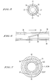
- the valve 24 is shown in detail in Figure 5. It has the form of a disc with cut-outs 27, and is retained by a spring ring 26. It permits one way flow into the cylinder space 25.
- piston 17 moves upwards and draws fluid from reservoir 22 via passages 23 and valve 24 into cylinder space 25.
- the flow causes valve 24 to rise and contact spring ring 26.
- fluid enters cylinder space 25 via cut-outs 27 of valve 24.
- the internal volume change caused by rod 19 rising is compensated for by rolling diaphragm 28 which is energized by piston 29 and spring 30.
- the load from said spring 30 maintains the reservoir pressure at slightly above atmospheric.
- piston 17 As piston 17 rises it meets minimal resistance until piston end 31 reaches port edge 32, which occurs at the piston displacement that corresponds to the position of the shin and foot assembly 2 at the instant of toe off. As the shin and foot assembly 2 continue to flex, piston 17 continues to rise and forces fluid through valve 20, thus causing it to close. Once valve 20 closes, the fluid in cylinder space 33 becomes pressurized and thus creates a force which resists further flexion. The fluid now being displaced by piston 17 is forced through the sharp edged variable orifice 34. It will be noted that piston 17 is shown as a plain cylinder having a close fit in bore 18, however a slightly smaller cylinder with a piston ring could perform the same function.
- piston 17 moves downwards and fluid is drawn from reservoir 22 via passages 43 into annular chamber 44.
- Valve 20 opens by an amount determined by spring ring 45 and fluid enters cylinder space 33.
- the internal volume changes caused by rod 19 retracting are compensated for by rolling diaphragm 28 in the manner previously described but in the reverse direction.
- piston 17 moves downwards it provides minimal resistance until piston edge 46 reaches port edge 47, which event occurs at a piston displacement that corresponds to the position of the shin assembly near the fully extended position.
- valve 24 closes and fluid is forced through variable orifice 34, causing the fluid in cylinder space 25 to become pressurized and thus creating a damping force which resists further extension of the limb.
- the adjustment of said damping force is then the same as previously described for the flexion stroke.
- Piston 17 then has an annular space 51 into which fits buffer 52 which is retained in said annular space by spring ring 53.
- Buffer 52 has an annular projection 54 which is larger than the flange of valve 20 so that said valve 20 can still open when annular projection 54 is in contact with end wall 55.
- Spring 56 is preloaded to the required level and when annular projection 54 contacts end wall 55, the spring 56 is further compressed as piston 17 moves upwards and a returning force is thus generated.
- control unit 61 is pivotally connected to thigh piece 60 and to shin assembly 2 in the same manner as previously described, however it can be seen that the effective line of action of control unit 61 here passes posterior to the knee axis 3 and that the unit retracts when said shin assembly is flexed.
- piston 63 replaces piston 17 and cylinder 64 replaces cylinder 41.
- Piston 63 has an annular groove with edges 67 and 69.
- An internal passage 71 of the piston communicates this annular groove with the bottom surface 65 of the piston. Note that these alternative parts are necessary to accommodate the different displacements and port arrangements and that all other components are identical to those previously described.
- piston 63 moves downwards and draws fluid from annular reservoir 22 into cylinder space 33 via passages 43 and valve 20 in the same manner as previously described.
- piston edge 65 reaches port edge 66
- piston edge 67 reaches port edge 68, which occurs at the piston displacement that corresponds to the position of shin assembly 2 at the instant of toe off.
- piston 63 descends further, causing fluid in cylinder space 25 to become pressurized, thus creating a force which resists flexion.
- the level of resistance can be adjusted by variable orifice 34 in the same manner as previously described.
- piston 63 moves upwards with fluid being drawn into cylinder chamber 25 in the manner previously described, and with the unit providing minimal resistance until piston edge 72 reaches port edge 73, which occurs at a piston displacement near to the fully extended position, and the unit starts to resist extension in the manner previously described.
Landscapes
- Health & Medical Sciences (AREA)
- Transplantation (AREA)
- Biomedical Technology (AREA)
- Cardiology (AREA)
- Oral & Maxillofacial Surgery (AREA)
- Engineering & Computer Science (AREA)
- Heart & Thoracic Surgery (AREA)
- Vascular Medicine (AREA)
- Life Sciences & Earth Sciences (AREA)
- Animal Behavior & Ethology (AREA)
- General Health & Medical Sciences (AREA)
- Public Health (AREA)
- Veterinary Medicine (AREA)
- Orthopedic Medicine & Surgery (AREA)
- Prostheses (AREA)
Priority Applications (1)
| Application Number | Priority Date | Filing Date | Title |
|---|---|---|---|
| EP01304695A EP1262155A1 (de) | 2001-05-29 | 2001-05-29 | Schwungphasensteuerung für künstliche untere Gliedmassen |
Applications Claiming Priority (1)
| Application Number | Priority Date | Filing Date | Title |
|---|---|---|---|
| EP01304695A EP1262155A1 (de) | 2001-05-29 | 2001-05-29 | Schwungphasensteuerung für künstliche untere Gliedmassen |
Publications (1)
| Publication Number | Publication Date |
|---|---|
| EP1262155A1 true EP1262155A1 (de) | 2002-12-04 |
Family
ID=8181991
Family Applications (1)
| Application Number | Title | Priority Date | Filing Date |
|---|---|---|---|
| EP01304695A Withdrawn EP1262155A1 (de) | 2001-05-29 | 2001-05-29 | Schwungphasensteuerung für künstliche untere Gliedmassen |
Country Status (1)
| Country | Link |
|---|---|
| EP (1) | EP1262155A1 (de) |
Cited By (2)
| Publication number | Priority date | Publication date | Assignee | Title |
|---|---|---|---|---|
| US6613097B1 (en) | 1999-06-28 | 2003-09-02 | Ohio Willow Wood Company | Swing phase control for an artificial lower limb |
| GB2399503A (en) * | 2003-03-20 | 2004-09-22 | Blatchford & Sons Ltd | Prosthetic knee joint mechanism |
Citations (6)
| Publication number | Priority date | Publication date | Assignee | Title |
|---|---|---|---|---|
| DE1075277B (de) * | 1960-02-11 | Ing Hans Adolph Mauch Dayton Ohio Dipl (V St A) | Beinprothese fur Oberschenkelamputierte | |
| GB2253791A (en) * | 1991-03-14 | 1992-09-23 | Blatchford & Sons Ltd | An artificial leg |
| EP0549855A2 (de) * | 1991-12-05 | 1993-07-07 | Otto Bock Orthopädische Industrie Besitz- und Verwaltungs-Kommanditgesellschaft | Einrichtung zum Steuern der Bewegung eines künstlichen Kniegelenks einer Oberschenkelprothese |
| EP0668065A1 (de) * | 1994-01-21 | 1995-08-23 | Mauch Laboratories, Inc. | Hydraulische Kontrolleinheit für Beinprothese |
| GB2338653A (en) * | 1998-06-26 | 1999-12-29 | Blatchford & Sons Ltd | A lower limb prosthesis |
| WO2000027318A1 (en) * | 1998-11-10 | 2000-05-18 | Mauch, Inc. | Computer controlled hydraulic resistance device for a prosthesis and other apparatus |
-
2001
- 2001-05-29 EP EP01304695A patent/EP1262155A1/de not_active Withdrawn
Patent Citations (6)
| Publication number | Priority date | Publication date | Assignee | Title |
|---|---|---|---|---|
| DE1075277B (de) * | 1960-02-11 | Ing Hans Adolph Mauch Dayton Ohio Dipl (V St A) | Beinprothese fur Oberschenkelamputierte | |
| GB2253791A (en) * | 1991-03-14 | 1992-09-23 | Blatchford & Sons Ltd | An artificial leg |
| EP0549855A2 (de) * | 1991-12-05 | 1993-07-07 | Otto Bock Orthopädische Industrie Besitz- und Verwaltungs-Kommanditgesellschaft | Einrichtung zum Steuern der Bewegung eines künstlichen Kniegelenks einer Oberschenkelprothese |
| EP0668065A1 (de) * | 1994-01-21 | 1995-08-23 | Mauch Laboratories, Inc. | Hydraulische Kontrolleinheit für Beinprothese |
| GB2338653A (en) * | 1998-06-26 | 1999-12-29 | Blatchford & Sons Ltd | A lower limb prosthesis |
| WO2000027318A1 (en) * | 1998-11-10 | 2000-05-18 | Mauch, Inc. | Computer controlled hydraulic resistance device for a prosthesis and other apparatus |
Cited By (3)
| Publication number | Priority date | Publication date | Assignee | Title |
|---|---|---|---|---|
| US6613097B1 (en) | 1999-06-28 | 2003-09-02 | Ohio Willow Wood Company | Swing phase control for an artificial lower limb |
| GB2399503A (en) * | 2003-03-20 | 2004-09-22 | Blatchford & Sons Ltd | Prosthetic knee joint mechanism |
| GB2399503B (en) * | 2003-03-20 | 2006-03-29 | Blatchford & Sons Ltd | Prosthetic knee joint mechanism |
Similar Documents
| Publication | Publication Date | Title |
|---|---|---|
| US6613097B1 (en) | Swing phase control for an artificial lower limb | |
| US5948021A (en) | Hydraulic cylinders for limb gait control | |
| US5779735A (en) | Knee unit for above-knee prosthetic leg | |
| US4662486A (en) | Hydraulic device | |
| EP0668065B1 (de) | Hydraulische Kontrolleinheit für Beinprothese | |
| US3316558A (en) | Prosthetic leg with a hydraulic knee control | |
| US2619652A (en) | Artificial limb | |
| CA2232512A1 (en) | Computer controlled hydraulic resistance device for a prosthesis and other apparatus | |
| GB2338653A (en) | A lower limb prosthesis | |
| GB2122720A (en) | A shock absorber with adjustable orifice | |
| US20060293761A1 (en) | Hydraulic knee prosthesis | |
| WO2004082519A3 (en) | Prosthetic knee joint mechanism | |
| WO2014137664A1 (en) | Prosthetics using curved dampening cylinders | |
| GB2343848A (en) | Control unit for prosthesis | |
| CN112334095A (zh) | 阀和具有该阀的假体膝关节 | |
| US6997959B2 (en) | Multi-functional artifical knee joint | |
| US5888237A (en) | Artificial limb including air cylinder device | |
| US20070208431A1 (en) | Swing Phase Control Device | |
| EP1262155A1 (de) | Schwungphasensteuerung für künstliche untere Gliedmassen | |
| JP3235720B2 (ja) | 義 足 | |
| US2568052A (en) | Control valve | |
| US7344569B2 (en) | Closed position maintainable selector valve, knee torque device using the valve, and artificial leg | |
| US20250041081A1 (en) | Joint and method for setting a starting position | |
| US20230404779A1 (en) | Damper unit and orthopedic device | |
| CA2615994A1 (en) | Swing-phase controller with an artificial joint |
Legal Events
| Date | Code | Title | Description |
|---|---|---|---|
| PUAI | Public reference made under article 153(3) epc to a published international application that has entered the european phase |
Free format text: ORIGINAL CODE: 0009012 |
|
| AK | Designated contracting states |
Kind code of ref document: A1 Designated state(s): AT BE CH CY DE DK ES FI FR GB GR IE IT LI LU MC NL PT SE TR |
|
| AX | Request for extension of the european patent |
Free format text: AL;LT;LV;MK;RO;SI |
|
| 17P | Request for examination filed |
Effective date: 20030509 |
|
| AKX | Designation fees paid |
Designated state(s): AT DE FR GB |
|
| STAA | Information on the status of an ep patent application or granted ep patent |
Free format text: STATUS: THE APPLICATION HAS BEEN WITHDRAWN |
|
| 18W | Application withdrawn |
Effective date: 20050811 |