EP1262223B1 - Trägheitsabscheider - Google Patents
Trägheitsabscheider Download PDFInfo
- Publication number
- EP1262223B1 EP1262223B1 EP02008438A EP02008438A EP1262223B1 EP 1262223 B1 EP1262223 B1 EP 1262223B1 EP 02008438 A EP02008438 A EP 02008438A EP 02008438 A EP02008438 A EP 02008438A EP 1262223 B1 EP1262223 B1 EP 1262223B1
- Authority
- EP
- European Patent Office
- Prior art keywords
- separation
- lamellae
- separation lamellae
- disposed
- inlet
- Prior art date
- Legal status (The legal status is an assumption and is not a legal conclusion. Google has not performed a legal analysis and makes no representation as to the accuracy of the status listed.)
- Expired - Lifetime
Links
- 238000000926 separation method Methods 0.000 claims abstract description 51
- 239000012535 impurity Substances 0.000 claims description 33
- 239000007788 liquid Substances 0.000 claims description 20
- 238000002485 combustion reaction Methods 0.000 claims description 4
- 239000007789 gas Substances 0.000 claims 4
- 239000003921 oil Substances 0.000 description 14
- 239000000463 material Substances 0.000 description 8
- 239000002184 metal Substances 0.000 description 7
- 229910052751 metal Inorganic materials 0.000 description 7
- 239000000356 contaminant Substances 0.000 description 6
- 239000010779 crude oil Substances 0.000 description 6
- 238000010586 diagram Methods 0.000 description 6
- 239000004033 plastic Substances 0.000 description 5
- 229920003023 plastic Polymers 0.000 description 5
- 239000000428 dust Substances 0.000 description 3
- 239000002245 particle Substances 0.000 description 3
- 238000005452 bending Methods 0.000 description 2
- 230000003247 decreasing effect Effects 0.000 description 2
- 230000008021 deposition Effects 0.000 description 2
- 239000007787 solid Substances 0.000 description 2
- 230000001133 acceleration Effects 0.000 description 1
- 239000000853 adhesive Substances 0.000 description 1
- 238000004026 adhesive bonding Methods 0.000 description 1
- 230000001070 adhesive effect Effects 0.000 description 1
- 230000002411 adverse Effects 0.000 description 1
- 230000009286 beneficial effect Effects 0.000 description 1
- 239000000919 ceramic Substances 0.000 description 1
- 238000004140 cleaning Methods 0.000 description 1
- 150000001875 compounds Chemical class 0.000 description 1
- 238000011109 contamination Methods 0.000 description 1
- 230000001419 dependent effect Effects 0.000 description 1
- 230000007613 environmental effect Effects 0.000 description 1
- 238000001746 injection moulding Methods 0.000 description 1
- 238000004519 manufacturing process Methods 0.000 description 1
- 239000007769 metal material Substances 0.000 description 1
- 150000002739 metals Chemical class 0.000 description 1
- 230000001105 regulatory effect Effects 0.000 description 1
- 230000003716 rejuvenation Effects 0.000 description 1
- 238000007789 sealing Methods 0.000 description 1
- 239000011343 solid material Substances 0.000 description 1
- 239000000126 substance Substances 0.000 description 1
- 230000007704 transition Effects 0.000 description 1
- 239000002699 waste material Substances 0.000 description 1
Images




Classifications
-
- B—PERFORMING OPERATIONS; TRANSPORTING
- B01—PHYSICAL OR CHEMICAL PROCESSES OR APPARATUS IN GENERAL
- B01D—SEPARATION
- B01D45/00—Separating dispersed particles from gases or vapours by gravity, inertia, or centrifugal forces
- B01D45/04—Separating dispersed particles from gases or vapours by gravity, inertia, or centrifugal forces by utilising inertia
- B01D45/08—Separating dispersed particles from gases or vapours by gravity, inertia, or centrifugal forces by utilising inertia by impingement against baffle separators
-
- Y—GENERAL TAGGING OF NEW TECHNOLOGICAL DEVELOPMENTS; GENERAL TAGGING OF CROSS-SECTIONAL TECHNOLOGIES SPANNING OVER SEVERAL SECTIONS OF THE IPC; TECHNICAL SUBJECTS COVERED BY FORMER USPC CROSS-REFERENCE ART COLLECTIONS [XRACs] AND DIGESTS
- Y10—TECHNICAL SUBJECTS COVERED BY FORMER USPC
- Y10S—TECHNICAL SUBJECTS COVERED BY FORMER USPC CROSS-REFERENCE ART COLLECTIONS [XRACs] AND DIGESTS
- Y10S55/00—Gas separation
- Y10S55/14—Inertia separator
Definitions
- the invention relates to a Trägheitsabscheider according to the preamble of claim 1.
- the invention relates to an oil module according to claim 9 and a Cylinder head cover according to claim 10, in which the o.g. Inertia separator integrated is.
- an inertial separator which for mechanical Separating liquids and or solid particles from a gas stream is provided.
- This inertial separator consists of two together to form a hollow body connected sheet metal shells.
- the profiles of the first sheet metal shell in Direction of the gas flow are open.
- the profiles of the second sheet metal shell are contrary opened the gas flow.
- the profiles are made by incorporating slots in the Sheet metal shell formed with a subsequent bending of the slotted areas. The bent areas interlock, whereby the gas flow deflected twice before passing through the inertial separator. By this twice Diverting the gas flow, the entrained in the gas stream drops or Solid particles thrown against the profile by the centrifugal force.
- On the inside The profile of the profile is formed by a liquid film, which runs slowly downwards and got into a collecting channel.
- the object of the invention is to provide an inertial separator which is reliable the impurities are removed from a gas stream. This task is characterized by the features of claim 1.
- the inertial separator according to the invention is advantageously suitable for contaminants, such as. Remove dust or liquid drops from a gas stream.
- the inertial separator has a housing with an inlet through which the gas to be purified enters the inertial separator and an outlet, through which the purified gas exits.
- the inlet can handle a wide variety of cross sections, such as. circular or rectangular cross sections.
- the outlet can be analog to the inlet also have any cross sections, wherein the cross sections of the Inlet and outlet do not necessarily have to comply.
- the inlet can e.g. be designed as a circular bore and the outlet, for. as rectangular Window. In other variants, the inlet and the outlet can both in the Cross-sectional area as well as in the cross-sectional shape correspond.
- Separating fins are arranged in the housing between the inlet and the outlet, which are arc-shaped. Due to the arch shape have the Abscheidellamellen a concave side and a convex side.
- the separator slats can e.g. also have a waveform with multiple turning points.
- the separation lamellae may e.g. Made of plastic, where Of course, other materials such. Metals for the production of separation lamellae can be used. The choice of material for the separation lamellae is dependent on the required material properties or the environmental conditions hold true. At high temperatures, metallic materials are more suitable and at low thermal loads may be preferred for reasons of cost plastics become.
- the inertial separator has at least two first Abscheidellamellen, which are arranged at a distance linearly side by side. This distance becomes one Gap generated between the first Abscheidellamellen, which with its convex side are arranged facing the inlet. Offset to the linearly arranged first Abscheidelamellen are second, also linearly arranged Abscheidelamellen provided which with their concave sides the concave sides of the first Abscheidellamellen are arranged opposite one another. At the Abscheidellamellen is a drainage slope arranged on which the deposited impurities can run off. Here, a single drainage slope connects all first and second Abscheidellamellen or all first and second separator slats.
- This drainage slope is preferably at an angle between 0 ° and 90 ° relative to the inlet.
- the deposited impurities slide downwards, causing them can no longer be carried through the inertial separator. Farther Prevents the drainage slope, that a leakage air flow flows past the Abscheidelamellen.
- the contaminants such as e.g. Oil up again the crude oil side are passed and are thus the oil cycle again available.
- Other impurities, e.g. Dust if not returned to a cycle should be, in e.g. transported a waste container, which empties when needed becomes.
- This may have a surface structure which contains the impurities leads together. By merging the impurities they slide faster.
- the surface structure may be e.g. via depressions or grooves have, e.g. parallel or at any angle to the inflow direction of the Gas are arranged.
- the gas entering through the inlet passes through the convex sides of the separator louvers passed into the gap between the first Abscheidellamellen. Through the gap the gas stream is "bundled" and hits the center of the concave side of the second Abscheidellamellen on. Upon impact of the gas flow on the second Abscheidellamellen be the impurities are thrown against the Abscheidelamellen where drop-shaped Adhere impurities and drain off. Dust-like impurities also fall downward.
- the gas flow is divided by the concave side and deflected again. The deflection of the gas flow takes place in the region of the greatest acceleration, whereby the impurities are pressed by the centrifugal force against the Abscheidellamellen become.
- the purer the gas leaving the outlet should be the more rows of separation louvers should be arranged one behind the other.
- the purity of the gas also be regulated by the size of the gap between the Abscheidellamellen. ever the purer the gas should be, the lower the gap to choose. Please note that caused by the inertial pressure drop with decreasing gap size increases. Therefore, the gap size should be as large as possible to choose the ratio Separation efficiency to optimize pressure loss.
- the Abscheidellamellen are run with their wall thickness as thin as possible, with a sufficient stability of Abscheidelamellen must be guaranteed. in this connection may be the wall thickness of Abscheidellamellen from 0.1 to 10 millimeters.
- the stability the separation lamellae is the conditions of use or the loads, such. Inflow velocity of the gas, which act on the Abscheidellamellen adapt.
- the wall thickness of the Abscheidellamellen depends on the used Material. With higher-strength materials, lower wall thicknesses can be realized as with less solid materials. By correspondingly thin Abscheidellamellen the size and weight of the inertial separator can be reduced.
- the drainage slope on the second Abscheidellamellen arranged.
- the drainage slope can be e.g. in one piece with the separator lamellae be executed.
- the drainage slope as a separate Executed component and connected to the second Abscheidellamellen, wherein the Slope detachable with e.g. Screws or unsolvable by e.g. Gluing to the second Abscheidellamellen can be attached.
- the drainage slope closes with the first Abscheidellamellen from where between the drainage slope and the first Abscheidellamellen There is a small gap through which the deposited impurities can drain away.
- the first Abscheidellamellen Slope can be the deposited impurities of the first and the second Abscheidellamellen be removed on the same drainage slope.
- a drip nose is arranged on the drainage slope, whereby the Contaminants can flow better into a collecting space.
- This drip nose is designed so that it tapers downwards, whereby the detachment of the individual Drops at the bottom of the drip nose is favored.
- a further embodiment of the invention provides that the Abscheidellamellen in one Angle between 90 ° and 180 ° relative to the inlet are arranged. Through this Arrangement bounces the incoming gas first to the first Abscheidellamellen and must flow along it, with already deposited first impurities become. By this arrangement of Abscheidellamellen the gas flow is also "gently" deflected, which prevents extreme turbulence.
- the Abscheidellamellen in their lateral end portions which form the conclusion of the arch shape along the vertical edge, flow-optimized are executed. This will prevent the gas from separating the slats detached and the pressure loss caused by the Abscheidellamellen is minimized.
- the flow-optimized end regions can e.g. designed as curves or tips be. In an embodiment of the end portions as tips, the wall thickness of the tapers Abscheidellamellen steadily until no material is available. Thus, at the end areas there is no more surface to which the contaminants can adhere.
- the Abscheidellamellen are circular segments, especially as 1 ⁇ 4 to 3 ⁇ 4 circle segments. These circle segments are easy to produce and also have a continuous curve without Turning points on, whereby the pressure loss is reduced in the inertial separator.
- the first separator fins may be at any distance from the second separator fins be arranged, where they can also partially interlock. ever closer the Abscheidelamellen are arranged to each other, the greater the degree of separation for the impurities.
- a closable liquid drain is in the housing provided, which is arranged below the Abscheidellamellen. Through this liquid drain can separated from the gas flow liquid again transported back into a liquid container or disposed of from the system.
- a valve may be arranged, which opens when needed can be.
- an automated opening means of a controller or Regulation or a manual opening by a fitter done.
- the liquid drain at the lowest point in a collection room for the deposited Arranged impurities. As a result, the impurities accumulate over the liquid drain and the collection chamber can be emptied as best as possible. If Only dry particles are separated from the gas stream, so these can of course be removed by the liquid drain, the liquid drain then it is a dust carrier.
- An oil module for an internal combustion engine has a crude oil side with a crude oil inlet and a clean oil side with a clean oil outlet. Between the crude oil inlet and the pure oil outlet, an oil filter element is arranged, which is the crude oil side of the Pure oil side sealing separates and filters out impurities from the oil.
- This oil module has an inlet window for crankcase gas, wherein the crankcase gas by an inertial separator described above is passed and de-oiled. The de-oiled gas exits the oil module through a gas outlet. The separated oil becomes the crude oil side fed and thus returns to the oil circuit.
- a cylinder head cover for covering a cylinder head for an internal combustion engine has a gas inlet port and a gas outlet port. Between the Gas inlet port and the gas outlet port is an inertial separator described above arranged.
- an inertial separator described above arranged.
- the inertial separator is still at least one cyclone separator downstream, in which the already pre-cleaned by the inertial separator Gas is cleaned again.
- an inertia separator 10 is shown in section along the section line B-B Figure 2 shown.
- the inertial separator 10 has an inlet 11 and a Outlet 12.
- the outlet 12 is defined by Abscheidelamellen 13, which in two parallel Rows arranged are separated from the inlet 11.
- the Abscheidelamellen 13 are arcuate (see Figure 2) executed, whereby on the one hand on a concave side 14 and on the other hand have a convex side 15.
- the first in the flow direction arranged Abscheidelamellen 13 are with their convex side 15 of the inlet 11 facing arranged.
- the downstream arranged in the flow direction Abscheidellamellen 13 are arranged with their concave side 14 facing the inlet 11.
- the concave sides 14 of the two are arranged in parallel Rows of Abscheidelamellen 13 opposite. So that the gas flow diverted several times is, the rows of Abscheidelamellen 13 are offset by about half a arc arranged to each other.
- the two rows of Abscheidelamellen 13 are at a distance E of about 2mm arranged.
- Secondary separating slats 13 have a drainage slope 16 arranged. This drainage slope 16 is integral with the second Abscheidellamellen 13 executed. It runs, with respect to the inlet 11, at an angle of approximately 30 °, depending on which substances are to be removed from the gas stream this angle can be increased or decreased.
- the component with the second separation lamellae 13 and the drainage slope 16 is made of a plastic which is e.g. produced by injection molding.
- the housing 18 is also made of plastic, wherein the inlet 11 and the outlet 12 are integrated in this housing 18.
- the separator lamellae 13 and the housing 18 can of course also from others Materials such as e.g. Metal or ceramic exist.
- the first separation lamellae 13 are made in one piece with the housing 18.
- the housing has 18 a system 19 on. At this plant 19, the mounting surface 17 with adhesive fixed.
- the drainage slope can also be removed Compounds, such as e.g. Screws or snap connections, on the system 19 be attached.
- the housing 18 is sealed with a cover plate 20, whereby the to purifying gas flow only through the inlet 11 and flow through the outlet 12 can.
- a Drain plug 21 is arranged, which is screwed in a liquid drain 22. This drain plug 21 can be removed if necessary, whereby the deposited Impurities from the inertial separator 10 can be removed.
- an inertia separator 10 is shown in section along the section line A-A Figure 1 shown.
- the Figure 1 corresponding components are denoted by the same reference numerals Mistake.
- the series of the first separation fins 13 consists of three side by side arranged Abscheidelamellen 13, which are arranged at a distance A to each other are. This distance A is in both the first Abscheidellamellen 13 as well as in the second separation lamellae 13 the same.
- the gas to be purified flows into the inertial separator 10 through the inlet 11. It bounces off the row of first separator fins13, where it is deflected in such a way that flow through the distances A between the first Abscheidelamellen 13 therethrough got to. As in the flow direction behind the distances A, the second Abscheidellamellen 13, the gas can not flow directly to the outlet 12.
- the second Abscheidelamellen 13 are arranged such that the deepest portion of the concave Page 14 is located directly behind the distance A. It gets through the concave Page 14 of the second Abscheidelamellen 13 again deflected, with part of the impurities bounces against the Abscheidelamellen 13 and no longer with the gas flow is carried away.
- FIG. 3 a variant of an inertia separator 10 is shown in section along the section line B-B shown in Figure 2.
- the figure 1 corresponding components are the same Provided with reference numerals.
- the first Abborgelamellen 13 are made in two parts with the housing 18.
- the housing 18 has a receptacle 23, in which the first Abscheidellamellen 13 are glued.
- the first separator fins 13 may be used individually, i. each Abscheidelamelle 13 alone or with a rail (not shown), i. all first Abscheidelamellen 13 are connected to the rail (not shown) on which Housing attached.
- the housing 18 from another Material exist as the Abscheidellamellen 13.
- the second Abscheidelamellen 13 are connected to the housing 18 in the same way like the first separation fins 13.
- the outlet 12 is at a 30 ° angle to the inlet in this embodiment 11 arranged.
- In the inlet 11 is an inlet fitting 24 and in the outlet 12, an outlet fitting 25 is disposed. Both connectors 24,25 can be connected to gas lines (not shown).
- the second Abscheidelamellen 13 are in this embodiment with screws 26, which project through the mounting surface 17 are connected to the housing 18.
- a drip nose 27 On the drainage slope 16, which is arranged parallel to the outlet 12, is in this Embodiment arranged a drip nose 27.
- This drip nose 27 closes the Slope 16 from, wherein it tapers downwards.
- the cover plate 20 which has a recess 28.
- the depression 28 is configured such that the contaminants flow into the liquid drain 22.
- the drain plug 21 is unscrewed if necessary, whereby the deposited Liquid can drain.
- FIG. 4 shows a section through an inertia separator 10 in a variant.
- the Figure 3 corresponding components are provided with the same reference numerals.
- the outlet 12 is arranged analogously to FIG. 3 at an angle of 30 ° to the inlet 11.
- the Cover plate 20, however, has no recess 28.
- the Abscheidelamellen 13 are in this embodiment at an angle of 45 °, based on the inlet 11, arranged.
- the drainage slope 16 extends at an angle of approx. 80 ° to the inlet 11. At its lower end it has the drip edge 27 which allowing the deposited liquid to drip off.
- the contaminant-to-be-cleaned gas passes through the inlet 11 into the inertial separator 10 on. It hits the sloping Abscheidellamellen 13, where already deposit the first impurities. Subsequently, the gas through the Abscheidellamellen 13 deflected several times, thereby separating more impurities. The thus purified gas passes through the outlet 12 again from the inertial separator out. The deposited impurities flow along the separation lamellae 13 and the drainage slope 16 in the direction of liquid outlet 22. In the liquid drain 22, the drain plug 21 is screwed.
- the drain plug 21 is as Connecting piece formed, which with a hose (not shown) connected can be, whereby the separated liquid continuously from the inside of the Inertia separator 10 can be discharged.
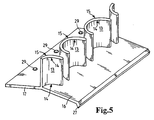
- FIG. 5 In Figure 5 are second Abscheidelamellen 13 with its drainage slope 16 according to Figure 3 in shown in perspective view.
- the figure 3 corresponding components are the same Provided with reference numerals.
- the Abscheidelamellen 13 are integral with the drainage slope 16 and the mounting surface 17 executed.
- In the mounting surface 17 are three mounting holes 29 arranged through which screws 26 (see FIG. 3) inserted through and with the housing 18 (see FIG. 3) can be screwed.
- FIG. 6 shows a schematic diagram of a flow course through the separation lamellae 13 is shown. 2 corresponding components are provided with the same reference numerals.
- the first and second separation fins 13 are 3 ⁇ 4 Circular arc executed, the circular arcs partially interlock.
- the amount of Distance E, ie how far the first and second separation fins 13 overlap, can be designed according to the deposited impurities. Of the Distance A between the Abscheidellamellen 13 a row may also be of a few Millimeters to a few centimeters, it is according to the deposited Design impurities.
- the gas to be cleaned flows along the arrows perpendicular to the first Abscheidellamellen 13.
- the gas stream is deflected arcuate and must by the distance A between the side by side Abscheidellamellen 13 flow through.
- the Arc shape of the second Abscheidelamellen 13 the gas flow is deflected and hits on the concave side 14 of the first Abscheidelamellen 13.
- FIG. 7 is a schematic diagram of an alternative flow path through the separation lamellae 13 is shown.
- the figure 6 corresponding components are the same Provided with reference numerals.
- the Abscheidellamellen 13 than 1 ⁇ 4 Bow executed.
- four parallel separating slats 13 are provided, which as two successively arranged pairs of Abscheidellamellen 13th are constructed according to FIG.
- In the flow direction behind the second Abscheidelamellen 13 third Abscheidelamellen 13 are arranged, which in their orientation correspond to the first Abscheidelamellen 13.
- the fourth separation lamellae 13 correspond to the second separation fins 13.
- the distance E of the first and second Abscheidelamellen 13 to each other is 2mm, whereby the gas flow less is strongly diverted. This results in a lower pressure loss through the Abscheidellamellen 13 to achieve.
- FIG. 8 is a schematic diagram of an alternative flow path through the separation lamellae 13 is shown.
- the figure 6 corresponding components are the same Provided with reference numerals.
- the Abscheidelamellen 13 are semicircular executed.
- the distance E of the Abscheidelamellen from each other is the same zero.
- the distance A between the Abscheidellamellen 13 a row is about 20mm.
- the inertial separator 10 (according to one of FIGS to 4) a lower pressure loss, as at the distance A of Figure 6.
- the separation area is arranged by three pairs Abscheidelamellen 13 generated. This triple separation area has a higher one Abscheidegrad, as a formed by two Abscheidellamellen 13 deposition area.
Landscapes
- Chemical & Material Sciences (AREA)
- Chemical Kinetics & Catalysis (AREA)
- Separating Particles In Gases By Inertia (AREA)
- Devices For Conveying Motion By Means Of Endless Flexible Members (AREA)
Description
- Figur 1
- einen Trägheitsabscheider im Schnitt,
- Figur 2
- einen Trägheitsabscheider im Schnitt,
- Figur 3
- einen Trägheitsabscheider im Schnitt,
- Figur 4
- einen Trägheitsabscheider im Schnitt,
- Figur 5
- zweite Abscheidelamellen mit ihrer Ablaufschräge,
- Figur 6
- eine Prinzipskizze eines Strömungsverlaufes,
- Figur 7
- eine Prinzipskizze eines Strömungsverlaufes.
- Figur 8
- eine Prinzipskizze eines Strömungsverlaufes.
Claims (10)
- Trägheitsabscheider (10), zur Abscheidung von Tropfen aus Kurbelgehäusegasen, aufweisend einen Einlass (11) und einen Auslass (12),dadurch gekennzeichnet, dasswobei zwischen dem Einlass (11) und dem Auslass (12) Abscheidelamellen (13) angeordnet sind, welche bogenförmig ausgebildet sind, wodurch sie eine konkave Seite (14) und eine konvexe Seite (15) aufweisen,wobei mindestens zwei erste Abscheidelamellen (13) mit einem Abstand A linear nebeneinander angeordnet sind und die konvexen Seiten (15) dem Einlass (11) zugewandt angeordnet sind,wobei versetzt zu den linear angeordneten ersten Abscheidelamellen (13) zweite Abscheidelamellen (13) angeordnet sind, welche mit ihren konkaven Seiten (14) den konkaven Seiten (14) der ersten Abscheidelamellen (13) gegenüberliegend angeordnet sind,
an den zweiten Abscheidelamellen (13) eine einzige ebene flächige Ablaufschräge (16) für die abgeschiedenen Verunreinigungen angeordnet ist, wobei die Ablaufschräge (16) die zweiten Abscheidelamellen (13) verbindet, und wobei die Ablaufschräge (16) über eine Oberflächenstruktur verfügt, wobei die Oberflächenstruktur durch Vertiefungen oder Rillen gebildet ist. - Trägheitsabscheider (10) nach Anspruch 1, dadurch gekennzeichnet, dass die Ablaufschräge (16) an den zweiten Abscheidelamellen (13) angeordnet ist und mit den ersten Abscheidelamellen (13) abschließt.
- Trägheitsabscheider (10) nach einem der Ansprüche 1 oder 2, dadurch gekennzeichnet, dass an der Ablaufschräge (16) eine Tropfnase (27) angeordnet ist.
- Trägheitsabscheider (10) nach einem der vorangehenden Ansprüche, dadurch gekennzeichnet, dass die Abscheidelamellen (13) in einem Winkel zwischen 90° und 180° zu dem Einlass (11) angeordnet sind.
- Trägheitsabscheider (10) nach einem der vorangehenden Ansprüche, dadurch gekennzeichnet, dass die Abscheidelamellen (13) in ihren Endbereichen strömungsoptimiert ausgeführt sind.
- Trägheitsabscheider (10) nach einem der vorangehenden Ansprüche, dadurch gekennzeichnet, dass die Abscheidelamellen (13) als Kreissegmente, insbesondere alls ¼ bis ¾ Kreissegmente ausgeführt sind.
- Trägheitsabscheider (10) nach Anspruch 6, dadurch gekennzeichnet, dass die Kreissegmente der Abscheidelamellen (13) teilweise ineinander greifen.
- Trägheitsabscheider (10) nach einem der vorangehenden Ansprüche, dadurch gekennzeichnet, dass ein verschließbarer Flüssigkeitsablauf vorgesehen ist, welcher unterhalb der Abscheidelamellen (13) angeordnet ist.
- Ölmodul für eine Brennkraftmaschine mit einem Eintrittsfenster für Kurbelgehäusegas, dadurch gekennzeichnet, dass ein Trägheitsabscheider (10) nach einem der vorangehenden Ansprüche integriert ist.
- Zylinderkopfhaube für eine Brennkraftmaschine mit einem Gaseinlassanschluss und einem Gasauslassanschluss, dadurch gekennzeichnet, dass ein Trägheitsabscheider (10) nach einem der Ansprüche 1 bis 8 integriert ist.
Applications Claiming Priority (2)
| Application Number | Priority Date | Filing Date | Title |
|---|---|---|---|
| DE10125404A DE10125404A1 (de) | 2001-05-25 | 2001-05-25 | Trägheitsabscheider |
| DE10125404 | 2001-05-25 |
Publications (2)
| Publication Number | Publication Date |
|---|---|
| EP1262223A1 EP1262223A1 (de) | 2002-12-04 |
| EP1262223B1 true EP1262223B1 (de) | 2005-11-23 |
Family
ID=7686031
Family Applications (1)
| Application Number | Title | Priority Date | Filing Date |
|---|---|---|---|
| EP02008438A Expired - Lifetime EP1262223B1 (de) | 2001-05-25 | 2002-04-13 | Trägheitsabscheider |
Country Status (4)
| Country | Link |
|---|---|
| US (1) | US6648939B2 (de) |
| EP (1) | EP1262223B1 (de) |
| AT (1) | ATE310575T1 (de) |
| DE (2) | DE10125404A1 (de) |
Families Citing this family (36)
| Publication number | Priority date | Publication date | Assignee | Title |
|---|---|---|---|---|
| DE10320493A1 (de) * | 2003-05-08 | 2004-12-02 | Volkswagen Ag | Brennkraftmaschine mit Kurbelgehäuseentlüftung |
| BRPI0508503B1 (pt) * | 2004-03-08 | 2015-01-13 | Reinz-Dichtungs-Gmbh | Dispositivo de separação de fluido e método para sua fabricação |
| DE102004018036A1 (de) * | 2004-04-08 | 2005-11-10 | Behr Gmbh & Co. Kg | Kühlsystem |
| US9790808B2 (en) * | 2005-04-04 | 2017-10-17 | Ecoservices, Llc | Mobile on-wing engine washing and water reclamation system |
| DE102007032768B4 (de) * | 2007-07-13 | 2015-06-03 | Reinz-Dichtungs-Gmbh | Ölabscheider und Ventilhaube, die selbigen Ölabscheider aufweist |
| DE102007053163A1 (de) * | 2007-11-08 | 2009-05-14 | Daimler Ag | Vorrichtung zum Abscheiden von Flüssigkeit aus einem Gasstrom und Brennstoffzellensystem einer derartigen Vorrichtung |
| US7837752B2 (en) * | 2007-12-03 | 2010-11-23 | Honeywell International Inc. | Water removal downstream of a turbine |
| US8047186B2 (en) * | 2008-11-24 | 2011-11-01 | Toyota Motor Engineering & Manufacturing North America, Inc. | Oil separator |
| KR101070648B1 (ko) * | 2009-02-02 | 2011-10-07 | 인제대학교 산학협력단 | 공기식 열교환기 |
| DE102010034615A1 (de) * | 2010-08-18 | 2012-02-23 | Gm Global Technology Operations Llc (N.D.Ges.D. Staates Delaware) | Ölabscheider |
| CN103245143B (zh) * | 2012-02-14 | 2016-09-21 | 浙江三花股份有限公司 | 气液分离器 |
| DE102013012965A1 (de) * | 2013-08-03 | 2015-02-05 | Gea Air Treatment Gmbh | Tropfenabscheider |
| JP6146202B2 (ja) * | 2013-08-22 | 2017-06-14 | トヨタ紡織株式会社 | オイルミストセパレータ |
| DE102014000914A1 (de) * | 2014-01-28 | 2015-07-30 | Carl Freudenberg Kg | Filterelement |
| JP2016014381A (ja) * | 2014-07-03 | 2016-01-28 | ナブテスコ株式会社 | 車両用空気圧縮装置 |
| CN104265403B (zh) * | 2014-09-29 | 2017-02-15 | 长城汽车股份有限公司 | 用于车辆的空气滤清器 |
| KR101961399B1 (ko) * | 2015-01-09 | 2019-07-17 | 게에아 에어 트리트먼트 게엠베하 | 액적 분리기 |
| US10227139B2 (en) | 2015-03-23 | 2019-03-12 | Rosemount Aerospace Inc. | Heated air data probes |
| US11209330B2 (en) | 2015-03-23 | 2021-12-28 | Rosemount Aerospace Inc. | Corrosion resistant sleeve for an air data probe |
| DE202015102560U1 (de) * | 2015-05-19 | 2016-08-22 | Woco Industrietechnik Gmbh | Vorrichtung zur Abscheidung von Partikeln aus einem Gasstrom |
| US9260993B1 (en) * | 2015-07-22 | 2016-02-16 | UPR Products, Inc. | Oil and air separator system and method |
| US9993760B2 (en) | 2015-08-07 | 2018-06-12 | Big Heart Pet, Inc. | Particle separator systems and processes for improving food safety |
| US10801500B2 (en) * | 2017-08-24 | 2020-10-13 | Ingersoll-Rand Industrial U.S., Inc. | Compressor system separator tank baffle |
| US10506903B2 (en) * | 2017-09-14 | 2019-12-17 | Skitter & Squirt Adventures, Llc | System and method for vacuum-powered debris separation |
| DE102018116526A1 (de) * | 2018-03-15 | 2019-09-19 | Dürr Systems Ag | Abscheidestufe sowie Abscheideeinheit mit wenigstens einer Abscheidestufe |
| US11414195B2 (en) | 2018-03-23 | 2022-08-16 | Rosemount Aerospace Inc. | Surface modified heater assembly |
| WO2020046778A1 (en) * | 2018-08-27 | 2020-03-05 | Cummins Filtration Ip, Inc. | Staggered array arrangement for air/liquid separation |
| US11002754B2 (en) | 2018-11-06 | 2021-05-11 | Rosemount Aerospace Inc. | Pitot probe with mandrel and pressure swaged outer shell |
| DE102019000498A1 (de) * | 2019-01-23 | 2020-07-23 | Deutz Aktiengesellschaft | Zylinderkopf |
| US10884014B2 (en) | 2019-03-25 | 2021-01-05 | Rosemount Aerospace Inc. | Air data probe with fully-encapsulated heater |
| US11428707B2 (en) | 2019-06-14 | 2022-08-30 | Rosemount Aerospace Inc. | Air data probe with weld sealed insert |
| US11826295B2 (en) * | 2020-11-25 | 2023-11-28 | Hill-Rom Services, Inc. | Port for an internal air distribution system of a patient support surface |
| US11662235B2 (en) | 2021-10-01 | 2023-05-30 | Rosemount Aerospace Inc. | Air data probe with enhanced conduction integrated heater bore and features |
| US11624637B1 (en) | 2021-10-01 | 2023-04-11 | Rosemount Aerospace Inc | Air data probe with integrated heater bore and features |
| WO2025015184A1 (en) * | 2023-07-11 | 2025-01-16 | Liquidat-R, LLC | Accumulator and dissipation assembly for capturing exigent vented volatile fluids |
| CN117264656B (zh) * | 2023-11-09 | 2025-08-01 | 中国石油化工股份有限公司 | 一种上流式反应器用集垢扩散器及上流式反应器 |
Family Cites Families (14)
| Publication number | Priority date | Publication date | Assignee | Title |
|---|---|---|---|---|
| US514439A (en) * | 1894-02-13 | Separator for removing lubricant from exhaust-steam | ||
| US692390A (en) * | 1898-04-02 | 1902-02-04 | A A Griffing Iron Company | Separator. |
| US1044208A (en) * | 1912-05-16 | 1912-11-12 | Max Luhn | Device for purifying the steam in steam-generators. |
| FR1056258A (fr) * | 1952-01-30 | 1954-02-25 | Tecalemit | Dispositif perfectionné pour l'épuration des fluides |
| FR2164984A6 (en) * | 1971-12-13 | 1973-08-03 | Alsthom | Parabolic baffle inertial filter - with baffle positions adjustable to counteract,blocking by snow |
| DE2641765C3 (de) * | 1976-09-16 | 1980-04-17 | Paul 6456 Langenselbold Gutermuth | Vorrichtung zum Abscheiden von kondensierbaren Anteilen |
| DE2720201C2 (de) * | 1977-05-05 | 1982-11-11 | Günter 8216 Reit im Winkl Wimböck | Fettfanggitter |
| DE8517835U1 (de) * | 1985-06-19 | 1985-11-14 | Gutermuth Jun., Paul, 6456 Langenselbold | Abscheider für gasförmige Fluide |
| DE8525075U1 (de) * | 1985-09-03 | 1985-11-14 | Prinz, Franz Josef, 7062 Rudersberg | Elektrostatisches Prallfilterelement |
| DE9112707U1 (de) * | 1991-10-12 | 1992-02-06 | Gutermuth Sen., Paul, 6456 Langenselbold | Abscheider für Fluide |
| ATE141401T1 (de) | 1993-03-02 | 1996-08-15 | Wimboeck Besitz Gmbh | Vorrichtung zum abscheiden von partikeln, insbesondere öl- oder fettpartikeln |
| DE9404440U1 (de) * | 1994-03-16 | 1994-05-26 | Gutermuth Patent Gmbh & Co. Kg, 63505 Langenselbold | Abscheider |
| DE19651857C1 (de) * | 1996-12-13 | 1998-02-19 | Evt Energie & Verfahrenstech | Vorrichtung zur Abscheidung von Feststoffen aus staubbeladenen Abgasen, insbesondere von Verbrennungsanlagen |
| DE20004131U1 (de) | 2000-03-04 | 2000-05-25 | Höfer, Andreas, Dr.-Ing., 31515 Wunstorf | Mechanisches Abscheidegitter zum Abscheiden von Flüssigkeits- und/oder Feststoffpartikeln aus einem Gasstrom |
-
2001
- 2001-05-25 DE DE10125404A patent/DE10125404A1/de not_active Withdrawn
-
2002
- 2002-04-13 EP EP02008438A patent/EP1262223B1/de not_active Expired - Lifetime
- 2002-04-13 DE DE50204998T patent/DE50204998D1/de not_active Expired - Fee Related
- 2002-04-13 AT AT02008438T patent/ATE310575T1/de not_active IP Right Cessation
- 2002-05-24 US US10/153,851 patent/US6648939B2/en not_active Expired - Fee Related
Also Published As
| Publication number | Publication date |
|---|---|
| US6648939B2 (en) | 2003-11-18 |
| EP1262223A1 (de) | 2002-12-04 |
| DE50204998D1 (de) | 2005-12-29 |
| ATE310575T1 (de) | 2005-12-15 |
| US20020189213A1 (en) | 2002-12-19 |
| DE10125404A1 (de) | 2002-11-28 |
Similar Documents
| Publication | Publication Date | Title |
|---|---|---|
| EP1262223B1 (de) | Trägheitsabscheider | |
| DE112015003481B4 (de) | Vorrichtung zum Abscheiden von Öltröpfchen und/oder Ölnebel | |
| EP1525376B1 (de) | Ölabscheider zur abscheidung von öl aus dem kurbelgehäuseentlüftungsgas einer brennkraftmaschine | |
| EP1080298B2 (de) | Ölabscheider zur entölung von kurbelgehäuse-entlüftungsgasen einer brennkraftmaschine | |
| EP1500423A1 (de) | Filterzusammenbau des Wirbeltyps | |
| DE102016106925B4 (de) | Ölabscheider mit einer Abscheiderkammer und einem Blow-by-Gaskanalaufbau | |
| WO2008019960A1 (de) | Vorrichtung zur abscheidung von flüssigkeiten aus gasen | |
| DE69607386T2 (de) | Eine flüssigkeit von gasabscheider und damit ausgerüstete brennkraftmaschine | |
| EP2333350A1 (de) | Druckluftbetriebener Unterdruckerzeuger | |
| DE3128470C2 (de) | Zyklonölabscheider | |
| DE19827296A1 (de) | Vorrichtung zur Abscheidung von Flüssigkeiten aus Gasen | |
| WO2001096729A1 (de) | Luftfiltersystem | |
| EP3117904A1 (de) | Abscheidevorrichtung für teilchen aus einem fluidstrom | |
| WO1998032955A1 (de) | Brennkraftmaschine mit einem ventilkammerdeckel | |
| EP1364696B1 (de) | Vorrichtung zur Reinigung eines Gasstromes | |
| DE102010006556B4 (de) | Luftfilter eines Verbrennungsmotors | |
| EP2702261B1 (de) | Luftfilterelement und gehäuse für ein luftfilterelement | |
| EP1755763B1 (de) | Tropfenabscheideranordnung | |
| EP1563909A2 (de) | Zyklonabscheidevorrichtung | |
| DE102010063843A1 (de) | Dunstabzugshaube und Verfahren zum Abscheiden von Aerosolen | |
| EP1839722B1 (de) | Abscheidevorrichtung zum Abscheiden von Teilchen | |
| EP2556873A1 (de) | Kondensatabschneider | |
| DE4344269A1 (de) | Luftreiniger für Fahrzeuge | |
| DE19807068A1 (de) | Fallrohrfilter | |
| DE3938194C2 (de) |
Legal Events
| Date | Code | Title | Description |
|---|---|---|---|
| PUAI | Public reference made under article 153(3) epc to a published international application that has entered the european phase |
Free format text: ORIGINAL CODE: 0009012 |
|
| AK | Designated contracting states |
Kind code of ref document: A1 Designated state(s): AT BE CH CY DE DK ES FI FR GB GR IE IT LI LU MC NL PT SE TR |
|
| AX | Request for extension of the european patent |
Free format text: AL;LT;LV;MK;RO;SI |
|
| 17P | Request for examination filed |
Effective date: 20030103 |
|
| AKX | Designation fees paid |
Designated state(s): AT BE CH CY DE DK ES FI FR GB GR IE IT LI LU MC NL PT SE TR |
|
| 17Q | First examination report despatched |
Effective date: 20030918 |
|
| RAP1 | Party data changed (applicant data changed or rights of an application transferred) |
Owner name: MANN + HUMMEL GMBH |
|
| GRAP | Despatch of communication of intention to grant a patent |
Free format text: ORIGINAL CODE: EPIDOSNIGR1 |
|
| GRAS | Grant fee paid |
Free format text: ORIGINAL CODE: EPIDOSNIGR3 |
|
| GRAA | (expected) grant |
Free format text: ORIGINAL CODE: 0009210 |
|
| AK | Designated contracting states |
Kind code of ref document: B1 Designated state(s): AT BE CH CY DE DK ES FI FR GB GR IE IT LI LU MC NL PT SE TR |
|
| PG25 | Lapsed in a contracting state [announced via postgrant information from national office to epo] |
Ref country code: IT Free format text: LAPSE BECAUSE OF FAILURE TO SUBMIT A TRANSLATION OF THE DESCRIPTION OR TO PAY THE FEE WITHIN THE PRESCRIBED TIME-LIMIT;WARNING: LAPSES OF ITALIAN PATENTS WITH EFFECTIVE DATE BEFORE 2007 MAY HAVE OCCURRED AT ANY TIME BEFORE 2007. THE CORRECT EFFECTIVE DATE MAY BE DIFFERENT FROM THE ONE RECORDED. Effective date: 20051123 Ref country code: FI Free format text: LAPSE BECAUSE OF FAILURE TO SUBMIT A TRANSLATION OF THE DESCRIPTION OR TO PAY THE FEE WITHIN THE PRESCRIBED TIME-LIMIT Effective date: 20051123 Ref country code: IE Free format text: LAPSE BECAUSE OF FAILURE TO SUBMIT A TRANSLATION OF THE DESCRIPTION OR TO PAY THE FEE WITHIN THE PRESCRIBED TIME-LIMIT Effective date: 20051123 Ref country code: NL Free format text: LAPSE BECAUSE OF FAILURE TO SUBMIT A TRANSLATION OF THE DESCRIPTION OR TO PAY THE FEE WITHIN THE PRESCRIBED TIME-LIMIT Effective date: 20051123 |
|
| REG | Reference to a national code |
Ref country code: GB Ref legal event code: FG4D Free format text: NOT ENGLISH |
|
| REG | Reference to a national code |
Ref country code: CH Ref legal event code: EP |
|
| REF | Corresponds to: |
Ref document number: 50204998 Country of ref document: DE Date of ref document: 20051229 Kind code of ref document: P |
|
| REG | Reference to a national code |
Ref country code: IE Ref legal event code: FG4D Free format text: LANGUAGE OF EP DOCUMENT: GERMAN |
|
| PG25 | Lapsed in a contracting state [announced via postgrant information from national office to epo] |
Ref country code: DK Free format text: LAPSE BECAUSE OF FAILURE TO SUBMIT A TRANSLATION OF THE DESCRIPTION OR TO PAY THE FEE WITHIN THE PRESCRIBED TIME-LIMIT Effective date: 20060223 Ref country code: GR Free format text: LAPSE BECAUSE OF FAILURE TO SUBMIT A TRANSLATION OF THE DESCRIPTION OR TO PAY THE FEE WITHIN THE PRESCRIBED TIME-LIMIT Effective date: 20060223 |
|
| REG | Reference to a national code |
Ref country code: SE Ref legal event code: TRGR |
|
| PG25 | Lapsed in a contracting state [announced via postgrant information from national office to epo] |
Ref country code: ES Free format text: LAPSE BECAUSE OF FAILURE TO SUBMIT A TRANSLATION OF THE DESCRIPTION OR TO PAY THE FEE WITHIN THE PRESCRIBED TIME-LIMIT Effective date: 20060306 |
|
| GBT | Gb: translation of ep patent filed (gb section 77(6)(a)/1977) |
Effective date: 20060315 |
|
| PGFP | Annual fee paid to national office [announced via postgrant information from national office to epo] |
Ref country code: FR Payment date: 20060411 Year of fee payment: 5 |
|
| PG25 | Lapsed in a contracting state [announced via postgrant information from national office to epo] |
Ref country code: AT Free format text: LAPSE BECAUSE OF NON-PAYMENT OF DUE FEES Effective date: 20060413 |
|
| PGFP | Annual fee paid to national office [announced via postgrant information from national office to epo] |
Ref country code: SE Payment date: 20060413 Year of fee payment: 5 |
|
| PGFP | Annual fee paid to national office [announced via postgrant information from national office to epo] |
Ref country code: DE Payment date: 20060419 Year of fee payment: 5 |
|
| PGFP | Annual fee paid to national office [announced via postgrant information from national office to epo] |
Ref country code: GB Payment date: 20060420 Year of fee payment: 5 |
|
| PG25 | Lapsed in a contracting state [announced via postgrant information from national office to epo] |
Ref country code: PT Free format text: LAPSE BECAUSE OF FAILURE TO SUBMIT A TRANSLATION OF THE DESCRIPTION OR TO PAY THE FEE WITHIN THE PRESCRIBED TIME-LIMIT Effective date: 20060424 |
|
| PG25 | Lapsed in a contracting state [announced via postgrant information from national office to epo] |
Ref country code: BE Free format text: LAPSE BECAUSE OF NON-PAYMENT OF DUE FEES Effective date: 20060430 Ref country code: CH Free format text: LAPSE BECAUSE OF NON-PAYMENT OF DUE FEES Effective date: 20060430 Ref country code: LI Free format text: LAPSE BECAUSE OF NON-PAYMENT OF DUE FEES Effective date: 20060430 Ref country code: MC Free format text: LAPSE BECAUSE OF NON-PAYMENT OF DUE FEES Effective date: 20060430 |
|
| NLV1 | Nl: lapsed or annulled due to failure to fulfill the requirements of art. 29p and 29m of the patents act | ||
| ET | Fr: translation filed | ||
| REG | Reference to a national code |
Ref country code: IE Ref legal event code: FD4D |
|
| PLBE | No opposition filed within time limit |
Free format text: ORIGINAL CODE: 0009261 |
|
| STAA | Information on the status of an ep patent application or granted ep patent |
Free format text: STATUS: NO OPPOSITION FILED WITHIN TIME LIMIT |
|
| 26N | No opposition filed |
Effective date: 20060824 |
|
| REG | Reference to a national code |
Ref country code: CH Ref legal event code: PL |
|
| GBPC | Gb: european patent ceased through non-payment of renewal fee |
Effective date: 20070413 |
|
| BERE | Be: lapsed |
Owner name: MANN + HUMMEL G.M.B.H. Effective date: 20060430 |
|
| PG25 | Lapsed in a contracting state [announced via postgrant information from national office to epo] |
Ref country code: DE Free format text: LAPSE BECAUSE OF NON-PAYMENT OF DUE FEES Effective date: 20071101 |
|
| PG25 | Lapsed in a contracting state [announced via postgrant information from national office to epo] |
Ref country code: GB Free format text: LAPSE BECAUSE OF NON-PAYMENT OF DUE FEES Effective date: 20070413 |
|
| PG25 | Lapsed in a contracting state [announced via postgrant information from national office to epo] |
Ref country code: SE Free format text: LAPSE BECAUSE OF NON-PAYMENT OF DUE FEES Effective date: 20070414 |
|
| PG25 | Lapsed in a contracting state [announced via postgrant information from national office to epo] |
Ref country code: FR Free format text: LAPSE BECAUSE OF NON-PAYMENT OF DUE FEES Effective date: 20070430 Ref country code: LU Free format text: LAPSE BECAUSE OF NON-PAYMENT OF DUE FEES Effective date: 20060413 Ref country code: TR Free format text: LAPSE BECAUSE OF FAILURE TO SUBMIT A TRANSLATION OF THE DESCRIPTION OR TO PAY THE FEE WITHIN THE PRESCRIBED TIME-LIMIT Effective date: 20051123 |
|
| PG25 | Lapsed in a contracting state [announced via postgrant information from national office to epo] |
Ref country code: CY Free format text: LAPSE BECAUSE OF FAILURE TO SUBMIT A TRANSLATION OF THE DESCRIPTION OR TO PAY THE FEE WITHIN THE PRESCRIBED TIME-LIMIT Effective date: 20051123 |