EP1262256A1 - Wälzlagerkäfig - Google Patents
Wälzlagerkäfig Download PDFInfo
- Publication number
- EP1262256A1 EP1262256A1 EP02008995A EP02008995A EP1262256A1 EP 1262256 A1 EP1262256 A1 EP 1262256A1 EP 02008995 A EP02008995 A EP 02008995A EP 02008995 A EP02008995 A EP 02008995A EP 1262256 A1 EP1262256 A1 EP 1262256A1
- Authority
- EP
- European Patent Office
- Prior art keywords
- cage
- sections
- pitch circle
- pockets
- outside
- Prior art date
- Legal status (The legal status is an assumption and is not a legal conclusion. Google has not performed a legal analysis and makes no representation as to the accuracy of the status listed.)
- Granted
Links
Images



Classifications
-
- F—MECHANICAL ENGINEERING; LIGHTING; HEATING; WEAPONS; BLASTING
- F16—ENGINEERING ELEMENTS AND UNITS; GENERAL MEASURES FOR PRODUCING AND MAINTAINING EFFECTIVE FUNCTIONING OF MACHINES OR INSTALLATIONS; THERMAL INSULATION IN GENERAL
- F16C—SHAFTS; FLEXIBLE SHAFTS; ELEMENTS OR CRANKSHAFT MECHANISMS; ROTARY BODIES OTHER THAN GEARING ELEMENTS; BEARINGS
- F16C33/00—Parts of bearings; Special methods for making bearings or parts thereof
- F16C33/30—Parts of ball or roller bearings
- F16C33/46—Cages for rollers or needles
- F16C33/54—Cages for rollers or needles made from wire, strips, or sheet metal
- F16C33/541—Details of individual pockets, e.g. shape or roller retaining means
-
- B—PERFORMING OPERATIONS; TRANSPORTING
- B21—MECHANICAL METAL-WORKING WITHOUT ESSENTIALLY REMOVING MATERIAL; PUNCHING METAL
- B21D—WORKING OR PROCESSING OF SHEET METAL OR METAL TUBES, RODS OR PROFILES WITHOUT ESSENTIALLY REMOVING MATERIAL; PUNCHING METAL
- B21D53/00—Making other particular articles
- B21D53/10—Making other particular articles parts of bearings; sleeves; valve seats or the like
- B21D53/12—Making other particular articles parts of bearings; sleeves; valve seats or the like cages for bearings
-
- F—MECHANICAL ENGINEERING; LIGHTING; HEATING; WEAPONS; BLASTING
- F16—ENGINEERING ELEMENTS AND UNITS; GENERAL MEASURES FOR PRODUCING AND MAINTAINING EFFECTIVE FUNCTIONING OF MACHINES OR INSTALLATIONS; THERMAL INSULATION IN GENERAL
- F16C—SHAFTS; FLEXIBLE SHAFTS; ELEMENTS OR CRANKSHAFT MECHANISMS; ROTARY BODIES OTHER THAN GEARING ELEMENTS; BEARINGS
- F16C19/00—Bearings with rolling contact, for exclusively rotary movement
- F16C19/22—Bearings with rolling contact, for exclusively rotary movement with bearing rollers essentially of the same size in one or more circular rows, e.g. needle bearings
- F16C19/44—Needle bearings
- F16C19/46—Needle bearings with one row or needles
- F16C19/463—Needle bearings with one row or needles consisting of needle rollers held in a cage, i.e. subunit without race rings
-
- F—MECHANICAL ENGINEERING; LIGHTING; HEATING; WEAPONS; BLASTING
- F16—ENGINEERING ELEMENTS AND UNITS; GENERAL MEASURES FOR PRODUCING AND MAINTAINING EFFECTIVE FUNCTIONING OF MACHINES OR INSTALLATIONS; THERMAL INSULATION IN GENERAL
- F16C—SHAFTS; FLEXIBLE SHAFTS; ELEMENTS OR CRANKSHAFT MECHANISMS; ROTARY BODIES OTHER THAN GEARING ELEMENTS; BEARINGS
- F16C33/00—Parts of bearings; Special methods for making bearings or parts thereof
- F16C33/30—Parts of ball or roller bearings
- F16C33/46—Cages for rollers or needles
- F16C33/54—Cages for rollers or needles made from wire, strips, or sheet metal
- F16C33/542—Cages for rollers or needles made from wire, strips, or sheet metal made from sheet metal
- F16C33/543—Cages for rollers or needles made from wire, strips, or sheet metal made from sheet metal from a single part
- F16C33/545—Cages for rollers or needles made from wire, strips, or sheet metal made from sheet metal from a single part rolled from a band
-
- F—MECHANICAL ENGINEERING; LIGHTING; HEATING; WEAPONS; BLASTING
- F16—ENGINEERING ELEMENTS AND UNITS; GENERAL MEASURES FOR PRODUCING AND MAINTAINING EFFECTIVE FUNCTIONING OF MACHINES OR INSTALLATIONS; THERMAL INSULATION IN GENERAL
- F16C—SHAFTS; FLEXIBLE SHAFTS; ELEMENTS OR CRANKSHAFT MECHANISMS; ROTARY BODIES OTHER THAN GEARING ELEMENTS; BEARINGS
- F16C33/00—Parts of bearings; Special methods for making bearings or parts thereof
- F16C33/30—Parts of ball or roller bearings
- F16C33/46—Cages for rollers or needles
- F16C33/54—Cages for rollers or needles made from wire, strips, or sheet metal
- F16C33/542—Cages for rollers or needles made from wire, strips, or sheet metal made from sheet metal
- F16C33/543—Cages for rollers or needles made from wire, strips, or sheet metal made from sheet metal from a single part
- F16C33/546—Cages for rollers or needles made from wire, strips, or sheet metal made from sheet metal from a single part with a M- or W-shaped cross section
Definitions
- the invention relates to a rolled from a sheet metal cage for cylindrical Rolling elements, in particular needle cages, with two side rings that pass through Pockets forming profiled webs are interconnected, the webs from mutually parallel, partly inside and partly outside of the pitch circle lying sections, which are inclined to the cage axis extending sections are interconnected.
- a cage of this generic type is known from DE-OS 21 47 170 previously known.
- This known method is based on a flat one Sheet metal strip, which can be rolled into the desired cross-sectional profile brings, either before profiling or afterwards the Punch out pockets for receiving the rolling elements and finally the tape bends round and welded if necessary at the joints.
- Profile-shaped M or W cages are the rolling elements by inside and holding edges arranged outside the pitch circle are held.
- the cages are made of thin-walled sheet metal because the small wall thickness enables particularly economical production of the bags by punching.
- this has the disadvantage that punching tears and overall rough punching surfaces are formed on the webs, d. H. the guide areas for the Rolling elements are rough and imprecise overall.
- stamping is done in such a way that each individual web of a cage is on both sides a force is applied by two pliers-like embossing tools, so that material displacement in the web area is realized. It is on the Hand that such a manufacturing technology due to the complex processing of each individual bridge is very complex and therefore expensive.
- the invention is based on the object of a generic cage to further develop its excellent running properties, d. H. the rolling elements start up in the pitch circle area, even without an additional one Can realize work process during its manufacturing process.
- this task is performed according to the characterizing part of Claim 1 solved in that in profiled, punched and unbent Condition of the metal strip in the area of the sloping sections Bags seen in plan view take a curved course such that a first convex arc B1 lying inward in the axial direction into one outer concave arc B2 passes over.
- the cage is M-shaped, i. H. its adjoining the side rings running parallel to the cage axis Sections are arranged outside the pitch circle. Is the cage designed according to claim 3 W-shaped, so are on the side rings themselves subsequent sections running parallel to the cage axis within the Pitch arranged.
- the Cage is guided outside, inside or rolling elements.
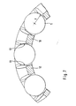
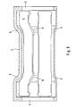
- the one shown in Figures 1 to 3 according to the prior art Cage consists of side rings 1 and 2, divided by a number evenly profiled webs 3 distributed around the circumference connected to one another are.
- the resulting pockets 4 for receiving rolling elements 5 are on the one hand by the side rings 1, 2, and on the other hand by the webs 3 limited.
- the webs 3 are in the direction of the bearing center over the pitch circle cranked through and consist of two on the side rings 1, 2 themselves subsequent sections 6, 7, which run parallel to the cage axis.
- the sections 6, 7 are outside the pitch circle and go obliquely in one each Section 8, 9 directed over the cage axis, which in turn is parallel to one another section running to the cage axis and lying within the pitch circle Unite 10.
- the punching process results in the punched-out process Cage belt the pockets 4 V-shaped d. H. in the radial direction their clear width becomes smaller inside.
- the rolling element 5 runs with his Rolling surface on the inner edge of the web sections 6, 7 so that it is outside of the pitch circle with the disadvantages described above.
- the sheet metal strip 12 shown in top view in FIG. 4 according to the invention is profiled, provided with punched pockets 4 and unbent.
- To the two edges which form the side rings 1, 2 of the cage in the bent state close sections 6 running parallel to the later cage axis, 7 on, d. H. in the curved state of the cage, these are outside the Pitch circle.
- Side rings 1, 2 and sections 6, 7 are therefore in the same Level.
- the sections 6, 7 are of the two inclined Sections 8, 9 continued, which then unite to section 10. In the bent state, the sections 8, 9 run obliquely to the cage axis, while section 10 runs parallel to the cage axis and within the Pitch circle lies.
- the subject of the invention is the contour of the pockets 4 in the oblique area extending section 8, 9, d. H. in the profile jump.
- the contour of the pockets 4 is in the area of the profile jump S-shaped in such a way that the inside in the axial direction lying first convex arc B1 in the outer second concave Sheet B2 passes over.
- the contour of the pocket 4 in the profile jump in the axial direction viewed from the inside out takes a convex / concave Course.
- the lower and the upper cutting edge are in the profile jump 13, 14 inclined to each other, so that the pocket 4 extends in width opens below.
- the application of force, illustrated by arrow F, d. H. the start the rolling element 5 thus advantageously only takes place in the circumferential direction.
- the main advantage of the invention is therefore that alone the design of the pocket geometry in the profile jump during punching with the bending of the band into a cage the separation between bracket the rolling element and the rolling element in the cage are started. This In contrast to the previous status of the Technology not by stamping the webs, but solely by the Contour of the pockets realized.
Landscapes
- Engineering & Computer Science (AREA)
- General Engineering & Computer Science (AREA)
- Mechanical Engineering (AREA)
- Rolling Contact Bearings (AREA)
Abstract
Description
- Figur 1
- einen Ausschnitt aus einer perspektivischen Darstellung eines M-Käfigs nach dem bisherigen Stand der Technik,
- Figuren 2 und 3
- einen teilweisen Längs- bzw. Querschnitt durch einen Käfig gemäß Figur 1,
- Figur 4
- eine Draufsicht auf ein profiliertes Käfigband in erfindungsgemäßer Ausführung,
- Figur 5
- einen Schnitt entlang der Linie V-V in Figur 4,
- Figur 6
- eine vergrößerte Darstellung einer Einzelheit X aus Figur 4,
- Figur 7
- einen teilweisen Querschnitt durch einen erfindungsgemäß ausgebildeten Käfig,
- Figur 8
- einen Ausschnitt einer perspektivischen Darstellung eines erfindungsgemäßen Käfigs und
- Figur 9
- einen Ausschnitt aus einem erfindungsgemäßen Käfig in perspektivischer Darstellung von innen betrachtet.
- 1
- Seitenring
- 2
- Seitenring
- 3
- Steg
- 4
- Tasche
- 5
- Wälzkörper
- 6
- Abschnitt
- 7
- Abschnitt
- 8
- Abschnitt
- 9
- Abschnitt
- 10
- Abschnitt
- 11
- Freiraum
- 12
- Band
- 13
- untere Schnittkante
- 14
- obere Schnittkante
- B1
- konvexer Bogen
- B2
- konkaver Bogen
Claims (5)
- Aus einem Blechband (12) gerollter Käfig für zylindrische Wälzkörper (5), insbesondere Nadelkäfig, mit zwei Seitenringen (1, 2), die durch Taschen (4) bildende profilierte Stege (3) miteinander verbunden sind, wobei die Stege (3) aus zueinander parallel verlaufenden, teils innerhalb und teils außerhalb des Teilkreises liegenden Abschnitten (10, 6, 7) bestehen, die durch schräg zur Käfigachse verlaufende Abschnitte (8, 9) miteinander verbunden sind, dadurch gekennzeichnet, dass im profilierten, gestanzten und ungebogenen Zustand des Blechbandes (12) im Bereich der schräg verlaufenden Abschnitte (8, 9) die Taschen (4) in der Draufsicht gesehen einen gekrümmten Verlauf derart nehmen, dass ein in axialer Richtung innen liegender erster konvexer Bogen B1 in einen außen liegenden zweiten konkaven Bogen B2 übergeht.
- Käfig nach Anspruch 1, dadurch gekennzeichnet, dass er M-förmig ausgebildet ist, wobei seine an den Seitenringen (1, 2) sich anschließenden parallel zur Käfigachse verlaufenden Abschnitte (6, 7) außerhalb des Teilkreises angeordnet sind.
- Käfig nach Anspruch 1, dadurch gekennzeichnet, dass er W-förmig ausgebildet ist, wobei seine an den Seitenringen (1,2) sich anschließenden parallel zur Käfigachse verlaufenden Abschnitte (6, 7) innerhalb des Teilkreises angeordnet sind.
- Käfig nach Anspruch 1, dadurch gekennzeichnet, dass er außen-, innenoder wälzkörpergeführt ist.
- Käfig nach Anspruch 1, dadurch gekennzeichnet, dass er in einem Kurbelzapfen oder in einem Planetenradlager eingesetzt ist.
Applications Claiming Priority (2)
| Application Number | Priority Date | Filing Date | Title |
|---|---|---|---|
| DE10126217A DE10126217A1 (de) | 2001-05-30 | 2001-05-30 | Wälzlagerkäfig |
| DE10126217 | 2001-05-30 |
Publications (2)
| Publication Number | Publication Date |
|---|---|
| EP1262256A1 true EP1262256A1 (de) | 2002-12-04 |
| EP1262256B1 EP1262256B1 (de) | 2004-07-07 |
Family
ID=7686572
Family Applications (1)
| Application Number | Title | Priority Date | Filing Date |
|---|---|---|---|
| EP02008995A Expired - Lifetime EP1262256B1 (de) | 2001-05-30 | 2002-04-23 | Wälzlagerkäfig |
Country Status (6)
| Country | Link |
|---|---|
| US (1) | US6648519B2 (de) |
| EP (1) | EP1262256B1 (de) |
| JP (1) | JP3999046B2 (de) |
| AT (1) | ATE270595T1 (de) |
| DE (2) | DE10126217A1 (de) |
| ES (1) | ES2220853T3 (de) |
Cited By (8)
| Publication number | Priority date | Publication date | Assignee | Title |
|---|---|---|---|---|
| WO2008067792A2 (de) | 2006-12-06 | 2008-06-12 | Schaeffler Kg | Wälzlagerkäfig |
| DE102011085716A1 (de) | 2011-11-03 | 2013-05-08 | Schaeffler Technologies AG & Co. KG | Radialkäfig für zylindrische Wälzkörper, insbesondere Nadelkranzkäfig |
| DE102011085713A1 (de) | 2011-11-03 | 2013-05-08 | Schaeffler Technologies AG & Co. KG | Radialkäfig für zylindrische Wälzkörper, insbesondere Nadelkranzkäfig |
| US8926191B2 (en) | 2010-05-03 | 2015-01-06 | Schaeffler Technologies AG & Co. KG | Axial cage for cylindrical rolling elements |
| CN104662313A (zh) * | 2012-10-05 | 2015-05-27 | Ntn株式会社 | 带有保持器的滚针组件 |
| CN105829746A (zh) * | 2013-12-17 | 2016-08-03 | 日本精工株式会社 | 径向滚子轴承用保持架 |
| US20160363166A1 (en) * | 2015-06-09 | 2016-12-15 | Aktiebolaget Skf | Radial cage for bearings having high rotational speeds |
| EP3770453A4 (de) * | 2018-03-20 | 2021-12-15 | Nakanishi Metal Works Co., Ltd. | Wälzlagerhalterung |
Families Citing this family (16)
| Publication number | Priority date | Publication date | Assignee | Title |
|---|---|---|---|---|
| DE102004031027A1 (de) * | 2004-06-26 | 2006-01-12 | Ina-Schaeffler Kg | Käfig für zylindrische Wälzkörper |
| JP4581542B2 (ja) | 2004-08-02 | 2010-11-17 | 日本精工株式会社 | 回転支持装置 |
| EP1741941B1 (de) * | 2005-07-04 | 2010-08-18 | NTN Corporation | Nadellager mit einem Käfig und Verfahren zur Herstellung des Käfigs |
| DE102006051676A1 (de) * | 2006-11-02 | 2008-05-08 | Schaeffler Kg | Käfig für ein Schrägrollenlager |
| JP5012438B2 (ja) * | 2007-11-09 | 2012-08-29 | 日本精工株式会社 | 針状ころ軸受 |
| DE102007060059A1 (de) | 2007-12-13 | 2009-06-18 | Schaeffler Kg | Wälzlagerkäfig |
| DE102008032662A1 (de) | 2008-04-15 | 2009-10-22 | Schaeffler Kg | Käfig für ein Wälzlager |
| DE102008026562A1 (de) | 2008-06-03 | 2009-12-10 | Schaeffler Kg | Wälzlager für hohe Drehzahlen |
| JP5499451B2 (ja) * | 2008-09-02 | 2014-05-21 | 株式会社ジェイテクト | 遊星歯車機構のころ軸受 |
| DE102008060752A1 (de) | 2008-12-05 | 2010-06-10 | Schaeffler Kg | Blechkäfig für zylindrische Wälzkörper und Verfahren zu seiner Herstellung |
| JP2013160292A (ja) * | 2012-02-03 | 2013-08-19 | Jtekt Corp | ころ軸受保持器及びころ軸受保持器の製造方法 |
| JP2014005918A (ja) * | 2012-06-27 | 2014-01-16 | Ntn Corp | シェル形ころ軸受、およびシェル形ころ軸受の製造方法 |
| DE102014212270A1 (de) * | 2014-06-26 | 2016-01-14 | Schaeffler Technologies AG & Co. KG | Käfig für ein Wälzlager, Wälzlager und Planetenradlagerung |
| DE102014214332A1 (de) * | 2014-07-23 | 2016-01-28 | Schaeffler Technologies AG & Co. KG | Käfig für ein Wälzlager, Wälzlager und Planetenradlagerung |
| DE102014224211A1 (de) | 2014-11-27 | 2016-06-02 | Schaeffler Technologies AG & Co. KG | Wälzlagerkäfig |
| JP7089369B2 (ja) * | 2018-01-09 | 2022-06-22 | Ntn株式会社 | 保持器付きころおよび遊星歯車支持構造 |
Citations (3)
| Publication number | Priority date | Publication date | Assignee | Title |
|---|---|---|---|---|
| DE2147170A1 (de) * | 1971-09-22 | 1973-03-29 | Schaeffler Ohg Industriewerk | Verfahren zur herstellung eines blechkaefigs fuer zylindrische waelzkoerper |
| US3992764A (en) * | 1975-09-22 | 1976-11-23 | The Torrington Company | Method of forming a roller cage |
| DE19740435A1 (de) * | 1997-09-15 | 1999-03-18 | Schaeffler Waelzlager Ohg | Verfahren zum Herstellen eines Käfigs |
Family Cites Families (5)
| Publication number | Priority date | Publication date | Assignee | Title |
|---|---|---|---|---|
| DE965459C (de) * | 1952-12-12 | 1957-06-06 | Duerkoppwerke Ag | Nadelrollenkaefig |
| US3110529A (en) * | 1960-06-25 | 1963-11-12 | Schaeffler Ohg Industriewerk | Cage for cylindrical rolling elements, more particularly needle cage |
| JP3357735B2 (ja) * | 1993-12-15 | 2002-12-16 | 日本トムソン株式会社 | 保持器付きころ |
| DE19702192A1 (de) * | 1997-01-23 | 1998-07-30 | Schaeffler Waelzlager Ohg | Käfig für zylindrische Wälzkörper |
| JPH11108065A (ja) * | 1997-08-06 | 1999-04-20 | Ntn Corp | 針状ころ軸受 |
-
2001
- 2001-05-30 DE DE10126217A patent/DE10126217A1/de not_active Withdrawn
-
2002
- 2002-04-23 DE DE50200589T patent/DE50200589D1/de not_active Expired - Lifetime
- 2002-04-23 ES ES02008995T patent/ES2220853T3/es not_active Expired - Lifetime
- 2002-04-23 EP EP02008995A patent/EP1262256B1/de not_active Expired - Lifetime
- 2002-04-23 AT AT02008995T patent/ATE270595T1/de not_active IP Right Cessation
- 2002-05-27 JP JP2002152696A patent/JP3999046B2/ja not_active Expired - Fee Related
- 2002-05-29 US US10/157,068 patent/US6648519B2/en not_active Expired - Lifetime
Patent Citations (3)
| Publication number | Priority date | Publication date | Assignee | Title |
|---|---|---|---|---|
| DE2147170A1 (de) * | 1971-09-22 | 1973-03-29 | Schaeffler Ohg Industriewerk | Verfahren zur herstellung eines blechkaefigs fuer zylindrische waelzkoerper |
| US3992764A (en) * | 1975-09-22 | 1976-11-23 | The Torrington Company | Method of forming a roller cage |
| DE19740435A1 (de) * | 1997-09-15 | 1999-03-18 | Schaeffler Waelzlager Ohg | Verfahren zum Herstellen eines Käfigs |
Cited By (16)
| Publication number | Priority date | Publication date | Assignee | Title |
|---|---|---|---|---|
| WO2008067792A3 (de) * | 2006-12-06 | 2008-11-20 | Schaeffler Kg | Wälzlagerkäfig |
| WO2008067792A2 (de) | 2006-12-06 | 2008-06-12 | Schaeffler Kg | Wälzlagerkäfig |
| US8926191B2 (en) | 2010-05-03 | 2015-01-06 | Schaeffler Technologies AG & Co. KG | Axial cage for cylindrical rolling elements |
| CN103089820B (zh) * | 2011-11-03 | 2017-12-19 | 舍弗勒技术股份两合公司 | 用于圆柱形滚动体的径向保持架,尤其是滚针轴承保持架 |
| DE102011085713A1 (de) | 2011-11-03 | 2013-05-08 | Schaeffler Technologies AG & Co. KG | Radialkäfig für zylindrische Wälzkörper, insbesondere Nadelkranzkäfig |
| US8702315B2 (en) | 2011-11-03 | 2014-04-22 | Schaeffler Technologies AG & Co. KG | Radial cage for cylindrical roller bodies |
| US8714833B2 (en) | 2011-11-03 | 2014-05-06 | Schaeffler Technologies AG & Co. KG | Radial cage for cylindrical roller bodies |
| CN103089820A (zh) * | 2011-11-03 | 2013-05-08 | 谢夫勒科技股份两合公司 | 用于圆柱形滚动体的径向保持架,尤其是滚针轴承保持架 |
| DE102011085716A1 (de) | 2011-11-03 | 2013-05-08 | Schaeffler Technologies AG & Co. KG | Radialkäfig für zylindrische Wälzkörper, insbesondere Nadelkranzkäfig |
| CN104662313A (zh) * | 2012-10-05 | 2015-05-27 | Ntn株式会社 | 带有保持器的滚针组件 |
| EP2905488A4 (de) * | 2012-10-05 | 2016-03-02 | Ntn Toyo Bearing Co Ltd | Nadelrollen mit halter |
| CN105829746A (zh) * | 2013-12-17 | 2016-08-03 | 日本精工株式会社 | 径向滚子轴承用保持架 |
| US10533607B2 (en) | 2013-12-17 | 2020-01-14 | Nsk Ltd. | Cage for radial roller bearing |
| US20160363166A1 (en) * | 2015-06-09 | 2016-12-15 | Aktiebolaget Skf | Radial cage for bearings having high rotational speeds |
| US9856915B2 (en) * | 2015-06-09 | 2018-01-02 | Aktiebolaget Skf | Radial cage for bearings having high rotational speeds |
| EP3770453A4 (de) * | 2018-03-20 | 2021-12-15 | Nakanishi Metal Works Co., Ltd. | Wälzlagerhalterung |
Also Published As
| Publication number | Publication date |
|---|---|
| ATE270595T1 (de) | 2004-07-15 |
| US6648519B2 (en) | 2003-11-18 |
| DE50200589D1 (de) | 2004-08-12 |
| DE10126217A1 (de) | 2002-12-05 |
| EP1262256B1 (de) | 2004-07-07 |
| JP2002364651A (ja) | 2002-12-18 |
| US20020181821A1 (en) | 2002-12-05 |
| JP3999046B2 (ja) | 2007-10-31 |
| ES2220853T3 (es) | 2004-12-16 |
Similar Documents
| Publication | Publication Date | Title |
|---|---|---|
| EP1262256B1 (de) | Wälzlagerkäfig | |
| DE10011651B4 (de) | Rotationssymmetrisches Formteil | |
| DE19881885C1 (de) | Nadellagerkäfig und Verfahren zu seiner Herstellung | |
| EP2066909A1 (de) | Wälzlagerkäfig und verfahren zur herstellung desselben | |
| DE20113853U1 (de) | Selbstlochendes, verdreh- und auspressicher in ein Blech einpressbares Befestigungselement | |
| DE4025011A1 (de) | Kugelfuehrung | |
| EP2222974A2 (de) | Wälzlagerkäfig | |
| DE19740435A1 (de) | Verfahren zum Herstellen eines Käfigs | |
| EP1568554B1 (de) | Blockierhülse für eine Lenksäule und Verfahren zur Herstellung derselben | |
| EP2893207B1 (de) | Axialkäfig für zylindrische wälzkörper | |
| DE10065431B4 (de) | Linearführungslager | |
| DE19736374A1 (de) | Wälzlager | |
| DE10214039A1 (de) | Rollenaufbau mit Käfig und Untersetzungsgetriebe zu dessen Verwendung | |
| DE10217463B4 (de) | Wälzlagerkäfig für zylindrische Wälzkörper, insbesondere Nadelkäfig | |
| DE2711882A1 (de) | Kugelbuechse | |
| DE7935982U1 (de) | Wälzlagerkäfig | |
| DE102004003655A1 (de) | Käfig für ein Zylinderrollenlager | |
| EP0222416B1 (de) | Einspannlagerbuchse | |
| DE4129111C2 (de) | Käfig für Rollenlager | |
| DE10240282B4 (de) | Radialwälzlager | |
| EP1588066B1 (de) | Wälzlagerkäfig | |
| WO2011003394A1 (de) | Käfig für ein kugellager und verfahren zur herstellung des käfigs | |
| DE4400718C2 (de) | Lager für eine Längs- und Drehbewegung | |
| DE68905643T2 (de) | Drehbare Stützeinrichtung und deren Herstellungsverfahren. | |
| WO2011047920A1 (de) | Radial-rollenwälzlager mit separaten borden aus blech |
Legal Events
| Date | Code | Title | Description |
|---|---|---|---|
| PUAI | Public reference made under article 153(3) epc to a published international application that has entered the european phase |
Free format text: ORIGINAL CODE: 0009012 |
|
| 17P | Request for examination filed |
Effective date: 20020423 |
|
| AK | Designated contracting states |
Kind code of ref document: A1 Designated state(s): AT BE CH CY DE DK ES FI FR GB GR IE IT LI LU MC NL PT SE TR |
|
| AX | Request for extension of the european patent |
Free format text: AL;LT;LV;MK;RO;SI |
|
| AKX | Designation fees paid |
Designated state(s): AT BE CH CY DE DK ES FI FR GB GR IE IT LI LU MC NL PT SE TR |
|
| GRAP | Despatch of communication of intention to grant a patent |
Free format text: ORIGINAL CODE: EPIDOSNIGR1 |
|
| GRAS | Grant fee paid |
Free format text: ORIGINAL CODE: EPIDOSNIGR3 |
|
| GRAA | (expected) grant |
Free format text: ORIGINAL CODE: 0009210 |
|
| AK | Designated contracting states |
Kind code of ref document: B1 Designated state(s): AT BE CH CY DE DK ES FI FR GB GR IE IT LI LU MC NL PT SE TR |
|
| PG25 | Lapsed in a contracting state [announced via postgrant information from national office to epo] |
Ref country code: NL Free format text: LAPSE BECAUSE OF FAILURE TO SUBMIT A TRANSLATION OF THE DESCRIPTION OR TO PAY THE FEE WITHIN THE PRESCRIBED TIME-LIMIT Effective date: 20040707 Ref country code: TR Free format text: LAPSE BECAUSE OF FAILURE TO SUBMIT A TRANSLATION OF THE DESCRIPTION OR TO PAY THE FEE WITHIN THE PRESCRIBED TIME-LIMIT Effective date: 20040707 Ref country code: FI Free format text: LAPSE BECAUSE OF FAILURE TO SUBMIT A TRANSLATION OF THE DESCRIPTION OR TO PAY THE FEE WITHIN THE PRESCRIBED TIME-LIMIT Effective date: 20040707 Ref country code: IE Free format text: LAPSE BECAUSE OF FAILURE TO SUBMIT A TRANSLATION OF THE DESCRIPTION OR TO PAY THE FEE WITHIN THE PRESCRIBED TIME-LIMIT Effective date: 20040707 |
|
| REG | Reference to a national code |
Ref country code: GB Ref legal event code: FG4D Free format text: NOT ENGLISH |
|
| REG | Reference to a national code |
Ref country code: CH Ref legal event code: EP |
|
| REG | Reference to a national code |
Ref country code: IE Ref legal event code: FG4D Free format text: GERMAN |
|
| REF | Corresponds to: |
Ref document number: 50200589 Country of ref document: DE Date of ref document: 20040812 Kind code of ref document: P |
|
| GBT | Gb: translation of ep patent filed (gb section 77(6)(a)/1977) |
Effective date: 20040901 |
|
| PG25 | Lapsed in a contracting state [announced via postgrant information from national office to epo] |
Ref country code: SE Free format text: LAPSE BECAUSE OF FAILURE TO SUBMIT A TRANSLATION OF THE DESCRIPTION OR TO PAY THE FEE WITHIN THE PRESCRIBED TIME-LIMIT Effective date: 20041007 Ref country code: DK Free format text: LAPSE BECAUSE OF FAILURE TO SUBMIT A TRANSLATION OF THE DESCRIPTION OR TO PAY THE FEE WITHIN THE PRESCRIBED TIME-LIMIT Effective date: 20041007 Ref country code: GR Free format text: LAPSE BECAUSE OF FAILURE TO SUBMIT A TRANSLATION OF THE DESCRIPTION OR TO PAY THE FEE WITHIN THE PRESCRIBED TIME-LIMIT Effective date: 20041007 |
|
| REG | Reference to a national code |
Ref country code: ES Ref legal event code: FG2A Ref document number: 2220853 Country of ref document: ES Kind code of ref document: T3 |
|
| NLV1 | Nl: lapsed or annulled due to failure to fulfill the requirements of art. 29p and 29m of the patents act | ||
| ET | Fr: translation filed | ||
| REG | Reference to a national code |
Ref country code: IE Ref legal event code: FD4D |
|
| PG25 | Lapsed in a contracting state [announced via postgrant information from national office to epo] |
Ref country code: AT Free format text: LAPSE BECAUSE OF NON-PAYMENT OF DUE FEES Effective date: 20050423 Ref country code: LU Free format text: LAPSE BECAUSE OF NON-PAYMENT OF DUE FEES Effective date: 20050423 Ref country code: CY Free format text: LAPSE BECAUSE OF FAILURE TO SUBMIT A TRANSLATION OF THE DESCRIPTION OR TO PAY THE FEE WITHIN THE PRESCRIBED TIME-LIMIT Effective date: 20050423 |
|
| PG25 | Lapsed in a contracting state [announced via postgrant information from national office to epo] |
Ref country code: BE Free format text: LAPSE BECAUSE OF NON-PAYMENT OF DUE FEES Effective date: 20050430 Ref country code: MC Free format text: LAPSE BECAUSE OF NON-PAYMENT OF DUE FEES Effective date: 20050430 |
|
| PLBE | No opposition filed within time limit |
Free format text: ORIGINAL CODE: 0009261 |
|
| STAA | Information on the status of an ep patent application or granted ep patent |
Free format text: STATUS: NO OPPOSITION FILED WITHIN TIME LIMIT |
|
| 26N | No opposition filed |
Effective date: 20050408 |
|
| BERE | Be: lapsed |
Owner name: *INA- SCHAEFFLER K.G. Effective date: 20050430 |
|
| PG25 | Lapsed in a contracting state [announced via postgrant information from national office to epo] |
Ref country code: LI Free format text: LAPSE BECAUSE OF NON-PAYMENT OF DUE FEES Effective date: 20060430 Ref country code: CH Free format text: LAPSE BECAUSE OF NON-PAYMENT OF DUE FEES Effective date: 20060430 |
|
| REG | Reference to a national code |
Ref country code: CH Ref legal event code: PL |
|
| BERE | Be: lapsed |
Owner name: *INA- SCHAEFFLER K.G. Effective date: 20050430 |
|
| PG25 | Lapsed in a contracting state [announced via postgrant information from national office to epo] |
Ref country code: PT Free format text: LAPSE BECAUSE OF NON-PAYMENT OF DUE FEES Effective date: 20041207 |
|
| PGFP | Annual fee paid to national office [announced via postgrant information from national office to epo] |
Ref country code: ES Payment date: 20080520 Year of fee payment: 7 Ref country code: FR Payment date: 20080312 Year of fee payment: 7 |
|
| PGFP | Annual fee paid to national office [announced via postgrant information from national office to epo] |
Ref country code: IT Payment date: 20080424 Year of fee payment: 7 |
|
| PGFP | Annual fee paid to national office [announced via postgrant information from national office to epo] |
Ref country code: GB Payment date: 20080423 Year of fee payment: 7 |
|
| GBPC | Gb: european patent ceased through non-payment of renewal fee |
Effective date: 20090423 |
|
| REG | Reference to a national code |
Ref country code: FR Ref legal event code: ST Effective date: 20091231 |
|
| PG25 | Lapsed in a contracting state [announced via postgrant information from national office to epo] |
Ref country code: GB Free format text: LAPSE BECAUSE OF NON-PAYMENT OF DUE FEES Effective date: 20090423 Ref country code: FR Free format text: LAPSE BECAUSE OF NON-PAYMENT OF DUE FEES Effective date: 20091222 |
|
| REG | Reference to a national code |
Ref country code: ES Ref legal event code: FD2A Effective date: 20090424 |
|
| PG25 | Lapsed in a contracting state [announced via postgrant information from national office to epo] |
Ref country code: ES Free format text: LAPSE BECAUSE OF NON-PAYMENT OF DUE FEES Effective date: 20090424 |
|
| PG25 | Lapsed in a contracting state [announced via postgrant information from national office to epo] |
Ref country code: IT Free format text: LAPSE BECAUSE OF NON-PAYMENT OF DUE FEES Effective date: 20090423 |
|
| REG | Reference to a national code |
Ref country code: DE Ref legal event code: R081 Ref document number: 50200589 Country of ref document: DE Owner name: SCHAEFFLER TECHNOLOGIES AG & CO. KG, DE Free format text: FORMER OWNER: SCHAEFFLER TECHNOLOGIES GMBH & CO. KG, 91074 HERZOGENAURACH, DE Effective date: 20120828 Ref country code: DE Ref legal event code: R081 Ref document number: 50200589 Country of ref document: DE Owner name: SCHAEFFLER TECHNOLOGIES GMBH & CO. KG, DE Free format text: FORMER OWNER: SCHAEFFLER TECHNOLOGIES GMBH & CO. KG, 91074 HERZOGENAURACH, DE Effective date: 20120828 |
|
| REG | Reference to a national code |
Ref country code: DE Ref legal event code: R081 Ref document number: 50200589 Country of ref document: DE Owner name: SCHAEFFLER TECHNOLOGIES GMBH & CO. KG, DE Free format text: FORMER OWNER: SCHAEFFLER TECHNOLOGIES AG & CO. KG, 91074 HERZOGENAURACH, DE Effective date: 20140218 Ref country code: DE Ref legal event code: R081 Ref document number: 50200589 Country of ref document: DE Owner name: SCHAEFFLER TECHNOLOGIES AG & CO. KG, DE Free format text: FORMER OWNER: SCHAEFFLER TECHNOLOGIES AG & CO. KG, 91074 HERZOGENAURACH, DE Effective date: 20140218 |
|
| REG | Reference to a national code |
Ref country code: DE Ref legal event code: R081 Ref document number: 50200589 Country of ref document: DE Owner name: SCHAEFFLER TECHNOLOGIES AG & CO. KG, DE Free format text: FORMER OWNER: SCHAEFFLER TECHNOLOGIES GMBH & CO. KG, 91074 HERZOGENAURACH, DE Effective date: 20150211 |
|
| PGFP | Annual fee paid to national office [announced via postgrant information from national office to epo] |
Ref country code: DE Payment date: 20200629 Year of fee payment: 19 |
|
| REG | Reference to a national code |
Ref country code: DE Ref legal event code: R119 Ref document number: 50200589 Country of ref document: DE |
|
| PG25 | Lapsed in a contracting state [announced via postgrant information from national office to epo] |
Ref country code: DE Free format text: LAPSE BECAUSE OF NON-PAYMENT OF DUE FEES Effective date: 20211103 |