EP1262343A2 - Procédé pour réguler ou commander la force d'amortissement d'un amortisseur réglable de véhicule - Google Patents
Procédé pour réguler ou commander la force d'amortissement d'un amortisseur réglable de véhicule Download PDFInfo
- Publication number
- EP1262343A2 EP1262343A2 EP02011117A EP02011117A EP1262343A2 EP 1262343 A2 EP1262343 A2 EP 1262343A2 EP 02011117 A EP02011117 A EP 02011117A EP 02011117 A EP02011117 A EP 02011117A EP 1262343 A2 EP1262343 A2 EP 1262343A2
- Authority
- EP
- European Patent Office
- Prior art keywords
- damper
- signal
- speed
- damper speed
- speed signal
- Prior art date
- Legal status (The legal status is an assumption and is not a legal conclusion. Google has not performed a legal analysis and makes no representation as to the accuracy of the status listed.)
- Granted
Links
- 238000000034 method Methods 0.000 title claims abstract description 38
- 238000013016 damping Methods 0.000 title description 12
- 230000001105 regulatory effect Effects 0.000 claims abstract description 11
- 230000001276 controlling effect Effects 0.000 claims abstract description 8
- 230000001133 acceleration Effects 0.000 claims description 11
- 230000015572 biosynthetic process Effects 0.000 claims description 7
- 230000010354 integration Effects 0.000 claims 1
- 230000008859 change Effects 0.000 description 6
- 238000010586 diagram Methods 0.000 description 6
- 230000008569 process Effects 0.000 description 4
- 239000000725 suspension Substances 0.000 description 3
- 238000005259 measurement Methods 0.000 description 2
- 238000012545 processing Methods 0.000 description 2
- 238000013459 approach Methods 0.000 description 1
- 238000006243 chemical reaction Methods 0.000 description 1
- 238000011161 development Methods 0.000 description 1
- 230000004069 differentiation Effects 0.000 description 1
- 238000006073 displacement reaction Methods 0.000 description 1
- 238000011156 evaluation Methods 0.000 description 1
- 230000005284 excitation Effects 0.000 description 1
- 239000012530 fluid Substances 0.000 description 1
- 230000009467 reduction Effects 0.000 description 1
- 230000004044 response Effects 0.000 description 1
- 238000005070 sampling Methods 0.000 description 1
- 238000012549 training Methods 0.000 description 1
Images


Classifications
-
- B—PERFORMING OPERATIONS; TRANSPORTING
- B60—VEHICLES IN GENERAL
- B60G—VEHICLE SUSPENSION ARRANGEMENTS
- B60G17/00—Resilient suspensions having means for adjusting the spring or vibration-damper characteristics, for regulating the distance between a supporting surface and a sprung part of vehicle or for locking suspension during use to meet varying vehicular or surface conditions, e.g. due to speed or load
- B60G17/015—Resilient suspensions having means for adjusting the spring or vibration-damper characteristics, for regulating the distance between a supporting surface and a sprung part of vehicle or for locking suspension during use to meet varying vehicular or surface conditions, e.g. due to speed or load the regulating means comprising electric or electronic elements
- B60G17/018—Resilient suspensions having means for adjusting the spring or vibration-damper characteristics, for regulating the distance between a supporting surface and a sprung part of vehicle or for locking suspension during use to meet varying vehicular or surface conditions, e.g. due to speed or load the regulating means comprising electric or electronic elements characterised by the use of a specific signal treatment or control method
-
- B—PERFORMING OPERATIONS; TRANSPORTING
- B60—VEHICLES IN GENERAL
- B60G—VEHICLE SUSPENSION ARRANGEMENTS
- B60G17/00—Resilient suspensions having means for adjusting the spring or vibration-damper characteristics, for regulating the distance between a supporting surface and a sprung part of vehicle or for locking suspension during use to meet varying vehicular or surface conditions, e.g. due to speed or load
- B60G17/06—Characteristics of dampers, e.g. mechanical dampers
- B60G17/08—Characteristics of fluid dampers
-
- B—PERFORMING OPERATIONS; TRANSPORTING
- B60—VEHICLES IN GENERAL
- B60G—VEHICLE SUSPENSION ARRANGEMENTS
- B60G2400/00—Indexing codes relating to detected, measured or calculated conditions or factors
- B60G2400/20—Speed
- B60G2400/202—Piston speed; Relative velocity between vehicle body and wheel
-
- B—PERFORMING OPERATIONS; TRANSPORTING
- B60—VEHICLES IN GENERAL
- B60G—VEHICLE SUSPENSION ARRANGEMENTS
- B60G2400/00—Indexing codes relating to detected, measured or calculated conditions or factors
- B60G2400/20—Speed
- B60G2400/204—Vehicle speed
-
- B—PERFORMING OPERATIONS; TRANSPORTING
- B60—VEHICLES IN GENERAL
- B60G—VEHICLE SUSPENSION ARRANGEMENTS
- B60G2400/00—Indexing codes relating to detected, measured or calculated conditions or factors
- B60G2400/25—Stroke; Height; Displacement
- B60G2400/252—Stroke; Height; Displacement vertical
-
- B—PERFORMING OPERATIONS; TRANSPORTING
- B60—VEHICLES IN GENERAL
- B60G—VEHICLE SUSPENSION ARRANGEMENTS
- B60G2500/00—Indexing codes relating to the regulated action or device
- B60G2500/10—Damping action or damper
Definitions
- the invention relates to a method for regulating or controlling the damper force adjustable damper in vehicles, especially in motor vehicles according to the preamble of claim 1 and a device with the features of the preamble of claim 17.
- the invention is particularly for vehicles with a level control or Air suspension can be used advantageously.
- the current damper systems in vehicles can be divided into three Divide into groups, namely passive, semi-active and active damper systems. at In all of these damper systems, the size of the damping depends on the relative Speed of the damper. With passive damper systems this is Size and direction of the force exerted by the damper only depend on the relative speed of the damper. In passive damper systems a change in the damper force during driving is not intended.
- the damper force can be changed of a fluid or gas flow can be changed by means of a valve.
- various control programs can be implemented using a Control element depending on the current driving situation Set the damper force.
- an actuator is used the desired force is provided in any direction, regardless of the relative speed of the damper.
- the object of the invention is to provide a method with which a generic Procedure for regulating or controlling the damper force can be improved. This task is accomplished through a process with the Features of claim 1 and a device with the features of the claim 17 solved.
- the Damper speed for each component to be damped especially for each Wheel or for each wheel suspension of a vehicle, determined individually.
- the distance sensors measure in order to keep the computing effort as low as possible the distance between a wheel and the vehicle body, so that the relative damper speed is very simple from two distance signals and the time between these two signals can be determined. It is Prerequisite that the signals are digitized in order to provide appropriate regulation or control.
- a further development of the invention provides that not only one damper speed signal about the difference formation of the distance signal via a Time interval is determined, but that also a second damper speed signal is determined in this way, but via a second Time interval that is greater than the time interval of the first damper speed signal is. Due to the different lengths of the time intervals at the Calculation of the respective damper speed signals are different Accuracies achieved, the damper speed being longer Time interval was determined, has a higher accuracy. However, it is second damper speed signal determined over a longer time interval slower and therefore less suitable for quick intervention.
- the first damper speed signal determined over a short time interval imprecise, however, can change very quickly due to the short pacing or acting external forces via a corresponding change the damper force to be reacted. Based on defined parameters or parameters a selection is then made, whether the exact one or the quick one Damper speed signal of further regulation or control of the Damper force is used.
- An expedient training provides that the first damper speed signal over a time interval of 0.5 msec to 5 msec and the second damper speed signal formed over a time interval from 5 msec to 50 msec becomes.
- the damper speed signal is selected simply and effectively by establishing a threshold value for the amount of the first damper speed signal. Exceeds the amount of the first damper speed signal exceeded a threshold, it means a quick Response due to the high vertical speed of the wheel is required. In this case, the regulation or control of the damper force becomes the first, that is based on fast and inaccurate damper speed signal. Otherwise, fast regulation or control can be dispensed with, so that the more accurate damper speed signal that over a longer time interval determined, can be used.
- the distance signal using a first and a first second low-pass filter is provided, the two low-pass filters being different Have time constants and accordingly different output signals generate the further calculation for the damper speed signals be taken as a basis.
- these filters also have a function with different sampling times of an "anti-aliasing filter".
- the first low-pass filter has a time constant of 0.25 msec to 2.5 msec and the second low-pass filter has a second time constant in a range from 2.5 msec to 25 msec. These time constants correspond to half of the respective time interval for the determination of the damper speed signals.
- damper speed signal is the Control or regulation of the damper force
- two output signals via two low-pass filters can be filtered out with different time constants.
- the amount of the difference signal between the first and the second output signal used as a parameter, based on which a selection of the damper speed signal is made.
- the time constants are also 0.25 msec to 2.5 msec for the first low-pass filter and 2.5 msec to 25 msec for the second low pass filter.
- An embodiment of the invention provides that the damper force after Skyhook method, the ground hook method or a combination this procedure is regulated. Depending on the precision required, that either a continuous control process is used, between choose a strong and a low damper force almost continuously can, or that a so-called on-off skyhook regulation is carried out, which switches between low and high damping.
- the damper speed required for the skyhook or ground hook method for the calculation of the inverse damper map can from the determined damper speed signals are calculated, and continue required assembly speed for the calculation of the relative damper speed can from an acceleration sensor arranged on the structure be determined.
- the build-up speed from a damper speed signal with filtered out Wheel speed component is determined.
- the more precise damper speed signal used and the corresponding wheel speed component is filtered out.
- the determination of the precise damper speed signal happens according to the method described above.
- FIG. 4a shows a damper characteristic curve of a passive damper system as a function of the quantities of damper force F d and damper speed V DK .
- the damper speed V DK is understood below to mean the relative damper speed, that is to say the speed which the damper has when the component to be damped moves relative to the corresponding component. In a vehicle, this would be the movement of the wheel relative to the vehicle body.
- the damper characteristic curve according to FIG. 4a shows an almost linear curve for small damper speeds V DK , which approaches a limit value for high damper speeds V DK . An adjustment or deliberate change in the damper characteristic curve is not provided in passive damper systems.
- FIG. 4b shows a damper map of a semi-active damper system, in which a large number of values for the damper force can be set between two limit values depending on the damper speed V DK . While it is possible to switch between the maximum and the minimum value in a discrete control system, there is the possibility in a continuous control system to select any value between the limit values and thereby to optimally adapt the damper force to the respective load.
- FIG. 3 An example of such a discrete control method is basically shown in FIG. 3, in which the product is formed from the damper speed V DK and the build-up speed V A.
- the body speed V A here does not denote the driving speed, but the vertical speed of the vehicle body.
- the Skyhook control procedure is explained using this diagram. If the relative damper speed V DK is positive, the damper force of the passive damper counteracts the movement and "pulls" the damper force down the vehicle body; If the relative damper speed V DK is negative, the damper force "pushes" the vehicle body upwards. So if the vertical speed V A of the vehicle body is negative, the vehicle body moves down and a maximum value of damping is desired to push the body up.
- Such an example is shown in the third section of FIG.
- the Skyhook control described simulates the ideal control configuration of a body displacement with a passive damper, which is arranged between the vehicle body and a fictitious counter bearing arranged outside the vehicle.
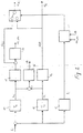
- FIG. 1 shows a block diagram for regulating the position of a damper valve 6, via which the damper force can be changed.
- the distance signal hi serves as the input variable, the index i subsequently denoting the component to be damped; in the case of a vehicle, this is in particular a wheel.
- a speed determination unit 1 the functioning of which is described in detail below in FIG. 2, the body speed V Ai and the damper speed V DK are determined.
- the body speed V Ai is fed together with the vehicle speed V V to a damper force setting unit 2, in which the damper force required is determined on the basis of the body speed V Ai in conjunction with the vehicle speed V V.
- the determined damper force F Di is output.
- the pre-control damper force F Vi is determined from the vehicle speed V V and dynamic factors D F.
- the braking pressure, the steering angle or the intended accelerations of the vehicle are reflected in the dynamic factors DF.
- These dynamic factors D F are, for example, tapped directly on the control elements such as the steering wheel or pedals, and due to the inertia of the overall vehicle with regard to steering, braking or acceleration actions, corresponding shifts in the vehicle body can be estimated in advance and a corresponding change in the damper force can be carried out on the corresponding damper.
- the pre-control damper force F Vi is output, which together with the damper force determined from the body speed V Ai and the vehicle speed V V results in the resulting requested damper force F resi .
- the resulting requested damper force F resi and the damper speed V DKi are supplied to an inverse damper map 4, where F resi and V DKi provide the input variables for determining the corresponding parameter for the setpoint current i si .
- the value of the setpoint current i si can be read directly from the characteristic diagram, the corresponding value for the damper speed V DKi having to be entered with reference to FIG. 4b.
- the corresponding value must be read off.
- the setpoint control current i si can thus be read directly from the inverse damper map 4, which is fed to an actuator 5, which in turn forwards the actually flowing current i isti to the damper valve 6.
- an actuator 5 which in turn forwards the actually flowing current i isti to the damper valve 6.
- the quantities of the body speed V Ai and the relative damper speed V DKi required for the calculation of the initially determined damper force F Di are calculated from the distance signal h i in the speed determination unit 1, the functioning of which is shown in detail in FIG. 2.
- the distance signal h i is fed to a first low-pass filter 11, a second low-pass filter 12 and a high-pass filter 15.
- the first low-pass filter has a time constant T 1 for determining a first output signal h si , which is sent to a calculation unit 13 for calculating a first speed signal V dsi and also to a link.
- the second low-pass filter 12 with a time constant T 2 which is greater than the time constant T 1 of the first low-pass filter 11, is also acted upon by the distance signal h i and filters out a second distance signal h li , which in turn is used by a calculation unit 14 for calculating the second speed signal V dli supplied and on the other hand is supplied with a negative sign of the link unit.
- the first filtered distance signal h si and the second filtered distance signal h li provided with a negative sign are added in the linking unit, and a difference signal ie, which is used as a parameter for the assessment of the damper speed signals to be used, is generated in the amount formation unit 16. The way in which this assessment is carried out will be explained later.
- the second damper speed signal V dli is supplied both to a switch 19 and, as can be seen in FIG. 1, to the damper force specification unit 2, from which the first determined damper force F Di is calculated in connection with the vehicle speed V v .
- the first damper speed signal V dsi is also fed to the switch 19 and, moreover, a magnitude formation unit 17 for forming the magnitude V ds-pos is determined.
- the distance signal h i is fed to a high-pass filter 15, which selects the wheel vibrations that can no longer be effectively set by the actuator.
- the high-pass filter 15 outputs a signal f i , which is forwarded to a logic unit 18.
- the variables of the difference signal d h and the amount of the first damper speed signal V ds-pos determined from the amount determination units 16 and 17 are also passed to this logic unit 18. Based on the incoming quantities, it is decided in this logic unit 18 which signal is to be transmitted to the switch 19. The decision as to which of the damper speed signals should be used as a basis for further processing is made on the basis of the evaluation of these incoming variables. If the magnitude of the first speed signal is greater than a first characteristic value or the difference signal is greater than a second characteristic value and the signal f i is less than a limit value, the first speed signal V ds is set as damper speed V DKi .
- FIG. 5 An example of the course of a control based on the damper speed is shown in FIG. 5, in which curve A represents the speed signal in a continuous measurement.
- Curve B is the digitized speed signal with a correspondingly short timing, which allows a very quick reaction to the speed changes.
- Another curve C is the digitized form of curve A over a larger time interval, as a result of which the slight fluctuations around a rest position are better compensated for.
- the limit values V ds-pos at a value of approx. 200 mm / sec and the difference signal D h .
- the amount V ds-pos exceeds the limit value, so that the first speed signal V dsi is used for further regulation of the damper force .
- the difference signal is smaller than the predetermined limit value, so that a switch is made to the more precise but slower second damper speed signal V dli .
- the slower speed signal V dli is also used as the difference signal d h is below the specified limit value.
Landscapes
- Engineering & Computer Science (AREA)
- Mechanical Engineering (AREA)
- Vehicle Body Suspensions (AREA)
Applications Claiming Priority (2)
| Application Number | Priority Date | Filing Date | Title |
|---|---|---|---|
| DE10126933A DE10126933B4 (de) | 2001-06-01 | 2001-06-01 | Verfahren zur Regelung oder Steuerung der Dämpferkraft verstellbarer Dämpfer an Fahrzeugen |
| DE10126933 | 2001-06-01 |
Publications (3)
| Publication Number | Publication Date |
|---|---|
| EP1262343A2 true EP1262343A2 (fr) | 2002-12-04 |
| EP1262343A3 EP1262343A3 (fr) | 2007-06-27 |
| EP1262343B1 EP1262343B1 (fr) | 2009-11-11 |
Family
ID=7687029
Family Applications (1)
| Application Number | Title | Priority Date | Filing Date |
|---|---|---|---|
| EP02011117A Expired - Lifetime EP1262343B1 (fr) | 2001-06-01 | 2002-05-18 | Procédé pour réguler ou commander la force d'amortissement d'un amortisseur réglable de véhicule |
Country Status (3)
| Country | Link |
|---|---|
| US (1) | US6847874B2 (fr) |
| EP (1) | EP1262343B1 (fr) |
| DE (2) | DE10126933B4 (fr) |
Families Citing this family (46)
| Publication number | Priority date | Publication date | Assignee | Title |
|---|---|---|---|---|
| DE10318110A1 (de) * | 2003-04-22 | 2004-11-11 | Continental Aktiengesellschaft | Verfahren zur Regelung einer Dämpfung |
| DE102005003292A1 (de) * | 2004-04-15 | 2005-11-03 | Continental Teves Ag & Co. Ohg | Langzeitoffsetabgleich eines Sensors |
| DE102004044474B4 (de) * | 2004-09-15 | 2012-10-18 | Bayerische Motoren Werke Aktiengesellschaft | Verfahren zur Ansteuerung eines aktiven oder semiaktiven Dämpfers im Fahrwerk eines Fahrzeugs |
| US7483775B2 (en) * | 2004-09-20 | 2009-01-27 | Gm Global Technology Operations, Inc. | Method and apparatus for controlling semi-active suspension components |
| DE102004053695B4 (de) * | 2004-11-06 | 2015-06-25 | Continental Teves Ag & Co. Ohg | Verfahren zur Dämpfung von Karosserie- und Fahrwerks oder Radschwingungen eines Kraftfahrzeuges |
| DE102005013970B4 (de) * | 2005-03-26 | 2017-10-26 | Bayerische Motoren Werke Aktiengesellschaft | Fahrdynamik-Regelsystem zum Reduzieren des Wankens |
| JP4546307B2 (ja) * | 2005-03-30 | 2010-09-15 | 本田技研工業株式会社 | 可変減衰力ダンパーの制御装置 |
| WO2006105677A2 (fr) * | 2005-04-07 | 2006-10-12 | Belimo Holding Ag | Suppression de vibrations |
| FR2890905B1 (fr) * | 2005-09-22 | 2009-01-16 | Peugeot Citroen Automobiles Sa | Dispositif de commande de suspension, vehicule muni de celui-ci, procede d'obtention et programme. |
| FR2890902B1 (fr) * | 2005-09-22 | 2007-12-14 | Peugeot Citroen Automobiles Sa | Dispositif de commande de suspension, vehicule muni de celui-ci, procede d'obtention et programme |
| FR2890900B1 (fr) * | 2005-09-22 | 2007-12-14 | Peugeot Citroen Automobiles Sa | Dispositif de commande de suspension, vehicule muni de celui-ci, procede d'obtention et programme. |
| DE102006001436B4 (de) * | 2006-01-10 | 2009-08-13 | Zf Friedrichshafen Ag | Verfahren zum Bestimmen wenigstens eines Bewegungszustands eines Fahrzeugaufbaus |
| JP4828325B2 (ja) * | 2006-07-03 | 2011-11-30 | カヤバ工業株式会社 | 緩衝器の制御装置 |
| DE102007040599B4 (de) * | 2007-08-27 | 2011-07-21 | ZF Friedrichshafen AG, 88046 | Verfahren und Vorrichtung zur Steuerung eines Schwingungsdämpfers und/oder einer Feder für ein Fahrzeug |
| DE102007049445B4 (de) * | 2007-10-16 | 2015-03-26 | Zf Friedrichshafen Ag | Verfahren zum Betrieb eines Luftfeder-Dämpfers |
| DE102008052997A1 (de) | 2007-10-26 | 2009-04-30 | Volkswagen Ag | Verfahren und System zur Beeinflussung der Bewegung eines in seinen Bewegungsabläufen steuerbaren oder regelbaren Fahrzeugaufbaus eines Kraftfahrzeuges und Fahrzeug |
| US8612094B2 (en) * | 2008-03-12 | 2013-12-17 | Steering Solutions Ip Holding Corporation | Systems and methods involving velocity dependent damping |
| US8839920B2 (en) | 2008-04-17 | 2014-09-23 | Levant Power Corporation | Hydraulic energy transfer |
| DE102009009063A1 (de) | 2009-02-16 | 2009-10-08 | Daimler Ag | Verfahren zum Regeln einer Federungseinrichtung und Federungseinrichtung |
| EP3643918B1 (fr) | 2010-06-16 | 2023-08-02 | ClearMotion, Inc. | Amortisseur de génération d'énergie intégré |
| US8731785B2 (en) | 2011-03-18 | 2014-05-20 | The Raymond Corporation | Dynamic stability control systems and methods for industrial lift trucks |
| US9403667B2 (en) | 2011-03-18 | 2016-08-02 | The Raymond Corporation | Dynamic vibration control systems and methods for industrial lift trucks |
| US8763990B2 (en) | 2012-03-20 | 2014-07-01 | The Raymond Corporation | Turn stability systems and methods for lift trucks |
| DE102012019619B4 (de) | 2012-10-06 | 2020-12-31 | Wabco Gmbh | Steuereinrichtung für ein Niveauregelsystem und Niveauregelsystem |
| US9302893B2 (en) | 2013-02-07 | 2016-04-05 | The Raymond Corporation | Vibration control systems and methods for industrial lift trucks |
| US9002557B2 (en) | 2013-03-14 | 2015-04-07 | The Raymond Corporation | Systems and methods for maintaining an industrial lift truck within defined bounds |
| US9702349B2 (en) | 2013-03-15 | 2017-07-11 | ClearMotion, Inc. | Active vehicle suspension system |
| US9809078B2 (en) | 2013-03-15 | 2017-11-07 | ClearMotion, Inc. | Multi-path fluid diverter valve |
| WO2014145018A2 (fr) | 2013-03-15 | 2014-09-18 | Levant Power Corporation | Améliorations apportées à la suspension active d'un véhicule |
| US9174508B2 (en) | 2013-03-15 | 2015-11-03 | Levant Power Corporation | Active vehicle suspension |
| EP3825156A1 (fr) | 2013-04-23 | 2021-05-26 | ClearMotion, Inc. | Suspension active dotée d'un actionneur structural |
| DE102013214742A1 (de) * | 2013-07-29 | 2015-01-29 | Bayerische Motoren Werke Aktiengesellschaft | Vorrichtung und Verfahren zur Fahrwerksregelung |
| DE102014205147B4 (de) | 2014-03-19 | 2024-06-27 | Bayerische Motoren Werke Aktiengesellschaft | Verfahren zur Einstellung einer Dämpferkraft, Dämpfer sowie zweispuriges Kraftfahrzeug mit wenigstens einem aktiven oder semiaktiven Dämpfer |
| DE102014208323A1 (de) | 2014-05-05 | 2015-11-05 | Bayerische Motoren Werke Aktiengesellschaft | Dämpfungssteuerungsanordnung und Aktuatoranordnung zur Ansteuerung eines adaptiven Fahrwerksdämpfers |
| US9702424B2 (en) | 2014-10-06 | 2017-07-11 | ClearMotion, Inc. | Hydraulic damper, hydraulic bump-stop and diverter valve |
| DE202015100442U1 (de) | 2015-01-14 | 2015-02-09 | Ford Global Technologies, Llc | Dämpfereinheit für ein Federungssystem mit einem semiaktiven Dämpfungsmittel |
| DE102015200383B4 (de) | 2015-01-14 | 2016-11-03 | Ford Global Technologies, Llc | Dämpfereinheit für ein Federungssystem mit einem semiaktiven Dämpfungsmittel |
| DE102015200384A1 (de) | 2015-01-14 | 2016-07-14 | Ford Global Technologies, Llc | Dämpfereinheit für ein Federungssystem mit einem semiaktiven Dämpfungsmittel |
| DE102015005964A1 (de) | 2015-05-08 | 2016-11-10 | Man Truck & Bus Ag | Verfahren zur Regelung oder Steuerung der Dämpferkraft verstellbarer Dämpfer in Kraftfahrzeugen, insbesondere in Nutzfahrzeugen |
| DE102015005966A1 (de) | 2015-05-08 | 2016-11-10 | Fludicon Gmbh | Verfahren und Vorrichtung zur Regelung oder Steuerung einer semiaktiven Dämpfereinrichtung eines Kraftfahrzeugs |
| DE102015011517B3 (de) * | 2015-09-03 | 2016-09-08 | Audi Ag | Verfahren zum Bestimmen einer aktuellen Niveaulage eines Fahrzeugs |
| DE102015013055B3 (de) * | 2015-10-08 | 2016-11-03 | Audi Ag | Verfahren und Vorrichtung zum Reduzieren von Schwingungen eines Fahrzeugrades |
| DE102016009081A1 (de) * | 2016-07-26 | 2018-02-01 | Man Truck & Bus Ag | Verfahren und Vorrichtung zur Steuerung oder Regelung einer Fahrerhaus-Lagerung |
| DE102017209439B4 (de) * | 2017-06-02 | 2023-12-28 | Bayerische Motoren Werke Aktiengesellschaft | Vorrichtung, Fortbewegungsmittel und Verfahren zur Ermittlung einer Vertikalbeschleunigung eines Rades eines Fortbewegungsmittels |
| KR102739193B1 (ko) * | 2020-07-30 | 2024-12-06 | 현대자동차주식회사 | 차량 서스펜션 제어 장치 및 방법 |
| CN119467606B (zh) * | 2024-11-11 | 2025-12-02 | 宁波普瑞均胜汽车电子有限公司 | 阻尼组件、传动装置、车载显示终端及车辆 |
Citations (2)
| Publication number | Priority date | Publication date | Assignee | Title |
|---|---|---|---|---|
| EP0704328A2 (fr) | 1994-09-29 | 1996-04-03 | Unisia Jecs Corporation | Procédé et dispositif de commande de la force d'amortissement d'une suspension de véhicule |
| DE19648176A1 (de) | 1996-11-21 | 1998-05-28 | Wabco Gmbh | Niveauregeleinrichtung mit Steuerung der Schwingungsdämpfer des Fahrwerks |
Family Cites Families (9)
| Publication number | Priority date | Publication date | Assignee | Title |
|---|---|---|---|---|
| DE3843137B4 (de) * | 1988-12-22 | 2004-04-01 | Robert Bosch Gmbh | Verfahren und Vorrichtung zur Steuerung eines Dämpfers |
| DE3918735A1 (de) * | 1989-06-08 | 1990-12-13 | Bosch Gmbh Robert | Verfahren und vorrichtung zur daempfung von bewegungsablaeufen |
| JPH04232111A (ja) * | 1990-06-23 | 1992-08-20 | Robert Bosch Gmbh | 信号処理方法及び装置 |
| DE4116839A1 (de) * | 1990-06-23 | 1992-01-09 | Bosch Gmbh Robert | Verfahren und schaltungssystem zur aufbereitung von signalen |
| US5475596A (en) * | 1991-05-20 | 1995-12-12 | General Motors Corporation | Full car semi-active suspension control based on quarter car control |
| US6259982B1 (en) * | 1993-02-02 | 2001-07-10 | Trw Inc. | Method and apparatus for controlling an active suspension system |
| JPH0858337A (ja) * | 1994-08-23 | 1996-03-05 | Nissan Motor Co Ltd | サスペンション制御装置 |
| JP3125603B2 (ja) * | 1994-10-07 | 2001-01-22 | トヨタ自動車株式会社 | サスペンション制御装置 |
| JP3118414B2 (ja) * | 1996-05-22 | 2000-12-18 | 株式会社豊田中央研究所 | 車両のばね上ばね下相対速度算出装置 |
-
2001
- 2001-06-01 DE DE10126933A patent/DE10126933B4/de not_active Expired - Fee Related
-
2002
- 2002-05-18 EP EP02011117A patent/EP1262343B1/fr not_active Expired - Lifetime
- 2002-05-18 DE DE50213984T patent/DE50213984D1/de not_active Expired - Lifetime
- 2002-06-03 US US10/158,922 patent/US6847874B2/en not_active Expired - Fee Related
Patent Citations (2)
| Publication number | Priority date | Publication date | Assignee | Title |
|---|---|---|---|---|
| EP0704328A2 (fr) | 1994-09-29 | 1996-04-03 | Unisia Jecs Corporation | Procédé et dispositif de commande de la force d'amortissement d'une suspension de véhicule |
| DE19648176A1 (de) | 1996-11-21 | 1998-05-28 | Wabco Gmbh | Niveauregeleinrichtung mit Steuerung der Schwingungsdämpfer des Fahrwerks |
Also Published As
| Publication number | Publication date |
|---|---|
| DE50213984D1 (de) | 2009-12-24 |
| US20020183907A1 (en) | 2002-12-05 |
| US6847874B2 (en) | 2005-01-25 |
| DE10126933A1 (de) | 2002-12-12 |
| EP1262343A3 (fr) | 2007-06-27 |
| DE10126933B4 (de) | 2004-08-26 |
| EP1262343B1 (fr) | 2009-11-11 |
Similar Documents
| Publication | Publication Date | Title |
|---|---|---|
| DE10126933B4 (de) | Verfahren zur Regelung oder Steuerung der Dämpferkraft verstellbarer Dämpfer an Fahrzeugen | |
| DE69517221T2 (de) | Vorrichtung und Verfahren zum Regeln der Dämpfungscharakteristiken von Fahrzeugstossdämpfern | |
| DE602004008718T2 (de) | Verfahren zum Steuern der Dämpfungskraft in einer elektronisch-gesteuerten Aufhängungsvorrichtung | |
| DE19943112B4 (de) | Regelsystem für einen federnden Tragemechanismus wie einen Federungsmechanismus eines Fahrzeugs | |
| DE19539566C1 (de) | Anordnung zur Steuerung einer Fahrwerk-Einrichtung | |
| DE4133237C2 (de) | System zur Fahrwerkregelung | |
| DE102009027939A1 (de) | Verfahren zur Fahrwerkregelung eines Kraftfahrzeugs, sowie Vorrichtung zur Durchführung | |
| DE112013003144B4 (de) | Aufhängungssteuerungssystem und Verfahren zum Steuern einer Aufhängungsvorrichtung | |
| EP0544108B1 (fr) | Système de commande d'une suspension semi-actif pour véhicules automobiles | |
| EP0262572B1 (fr) | Procédé de réglage de l'amortissement de véhicules à moteur | |
| DE4137712C2 (de) | Dämpfungssteuerung für semiaktive Fahrzeugschwingungsdämpfer | |
| DE4040376A1 (de) | Aufhaengungs-regeleinrichtung | |
| DE4233485A1 (de) | Aufhaengungssteuersystem fuer kraftfahrzeuge | |
| EP0844114B1 (fr) | Régulation de niveau avec commande des amortisseurs de la suspension | |
| DE4418625B4 (de) | Steuereinrichtung für eine Radaufhängung eines Fahrzeugs, Verfahren zur Einstellung der Federkonstanten und zur Einstellung des Dämpfungsmaßes einer Radaufhängung | |
| EP0450006B1 (fr) | Procede et dispositif pour la regulation du chassis | |
| DE4408292C2 (de) | Radaufhängungs-Steuersystem | |
| DE102016206604B4 (de) | Steuervorrichtung und Verfahren zum Regeln einer Dämpferhärte eines Schwingungsdämpfers eines Kraftfahrzeugs | |
| EP1331111A2 (fr) | Amortisseur réglable pour un véhicule automobile | |
| DE4015221A1 (de) | Vibrationssteuervorrichtung fuer eine fahrzeugkarosserie | |
| DE3928343A1 (de) | Anordnung zur aktiven fahrwerksdaempfung (afd) | |
| EP2052885B1 (fr) | Procédé et système destinés à influencer le mouvement d'une caisse d'un véhicule automobile ou d'un véhicule, pouvant être commandée ou réglée dans ses déroulements de mouvements | |
| EP2087255A1 (fr) | Dispositif et procédé pour l'asservissement d'un élément de palier | |
| DE102017212356B4 (de) | Verfahren zur Einstellung einer Dämpferkraft eines Schwingungsdämpfers sowie Steuervorrichtung für einen Schwingungsdämpfer und Kraftfahrzeug mit einem Schwingungsdämpfer und einer Steuervorrichtung | |
| DE10316114A1 (de) | Aktive Wankdämpfung |
Legal Events
| Date | Code | Title | Description |
|---|---|---|---|
| PUAI | Public reference made under article 153(3) epc to a published international application that has entered the european phase |
Free format text: ORIGINAL CODE: 0009012 |
|
| AK | Designated contracting states |
Kind code of ref document: A2 Designated state(s): AT BE CH CY DE DK ES FI FR GB GR IE IT LI LU MC NL PT SE TR |
|
| AX | Request for extension of the european patent |
Free format text: AL;LT;LV;MK;RO;SI |
|
| PUAL | Search report despatched |
Free format text: ORIGINAL CODE: 0009013 |
|
| AK | Designated contracting states |
Kind code of ref document: A3 Designated state(s): AT BE CH CY DE DK ES FI FR GB GR IE IT LI LU MC NL PT SE TR |
|
| AX | Request for extension of the european patent |
Extension state: AL LT LV MK RO SI |
|
| 17P | Request for examination filed |
Effective date: 20071227 |
|
| 17Q | First examination report despatched |
Effective date: 20080201 |
|
| AKX | Designation fees paid |
Designated state(s): DE ES FR IT SE |
|
| GRAP | Despatch of communication of intention to grant a patent |
Free format text: ORIGINAL CODE: EPIDOSNIGR1 |
|
| GRAS | Grant fee paid |
Free format text: ORIGINAL CODE: EPIDOSNIGR3 |
|
| GRAA | (expected) grant |
Free format text: ORIGINAL CODE: 0009210 |
|
| AK | Designated contracting states |
Kind code of ref document: B1 Designated state(s): DE ES FR IT SE |
|
| REF | Corresponds to: |
Ref document number: 50213984 Country of ref document: DE Date of ref document: 20091224 Kind code of ref document: P |
|
| PG25 | Lapsed in a contracting state [announced via postgrant information from national office to epo] |
Ref country code: SE Free format text: LAPSE BECAUSE OF FAILURE TO SUBMIT A TRANSLATION OF THE DESCRIPTION OR TO PAY THE FEE WITHIN THE PRESCRIBED TIME-LIMIT Effective date: 20091111 Ref country code: ES Free format text: LAPSE BECAUSE OF FAILURE TO SUBMIT A TRANSLATION OF THE DESCRIPTION OR TO PAY THE FEE WITHIN THE PRESCRIBED TIME-LIMIT Effective date: 20100222 |
|
| PLBE | No opposition filed within time limit |
Free format text: ORIGINAL CODE: 0009261 |
|
| STAA | Information on the status of an ep patent application or granted ep patent |
Free format text: STATUS: NO OPPOSITION FILED WITHIN TIME LIMIT |
|
| 26N | No opposition filed |
Effective date: 20100812 |
|
| PG25 | Lapsed in a contracting state [announced via postgrant information from national office to epo] |
Ref country code: IT Free format text: LAPSE BECAUSE OF FAILURE TO SUBMIT A TRANSLATION OF THE DESCRIPTION OR TO PAY THE FEE WITHIN THE PRESCRIBED TIME-LIMIT Effective date: 20091111 |
|
| REG | Reference to a national code |
Ref country code: DE Ref legal event code: R081 Ref document number: 50213984 Country of ref document: DE Owner name: CONTINENTAL TEVES AG & CO. OHG, DE Free format text: FORMER OWNER: CONTINENTAL AKTIENGESELLSCHAFT, 30165 HANNOVER, DE Effective date: 20110414 |
|
| REG | Reference to a national code |
Ref country code: FR Ref legal event code: PLFP Year of fee payment: 14 |
|
| REG | Reference to a national code |
Ref country code: FR Ref legal event code: PLFP Year of fee payment: 15 |
|
| REG | Reference to a national code |
Ref country code: FR Ref legal event code: PLFP Year of fee payment: 16 |
|
| PGFP | Annual fee paid to national office [announced via postgrant information from national office to epo] |
Ref country code: FR Payment date: 20170523 Year of fee payment: 16 Ref country code: DE Payment date: 20170531 Year of fee payment: 16 |
|
| REG | Reference to a national code |
Ref country code: DE Ref legal event code: R119 Ref document number: 50213984 Country of ref document: DE |
|
| PG25 | Lapsed in a contracting state [announced via postgrant information from national office to epo] |
Ref country code: FR Free format text: LAPSE BECAUSE OF NON-PAYMENT OF DUE FEES Effective date: 20180531 Ref country code: DE Free format text: LAPSE BECAUSE OF NON-PAYMENT OF DUE FEES Effective date: 20181201 |