EP1262688A2 - Spindelantrieb - Google Patents
Spindelantrieb Download PDFInfo
- Publication number
- EP1262688A2 EP1262688A2 EP02253830A EP02253830A EP1262688A2 EP 1262688 A2 EP1262688 A2 EP 1262688A2 EP 02253830 A EP02253830 A EP 02253830A EP 02253830 A EP02253830 A EP 02253830A EP 1262688 A2 EP1262688 A2 EP 1262688A2
- Authority
- EP
- European Patent Office
- Prior art keywords
- screw
- arrangement
- nut
- coupling
- actuator according
- Prior art date
- Legal status (The legal status is an assumption and is not a legal conclusion. Google has not performed a legal analysis and makes no representation as to the accuracy of the status listed.)
- Granted
Links
Images


Classifications
-
- F—MECHANICAL ENGINEERING; LIGHTING; HEATING; WEAPONS; BLASTING
- F16—ENGINEERING ELEMENTS AND UNITS; GENERAL MEASURES FOR PRODUCING AND MAINTAINING EFFECTIVE FUNCTIONING OF MACHINES OR INSTALLATIONS; THERMAL INSULATION IN GENERAL
- F16H—GEARING
- F16H25/00—Gearings comprising primarily only cams, cam-followers and screw-and-nut mechanisms
- F16H25/18—Gearings comprising primarily only cams, cam-followers and screw-and-nut mechanisms for conveying or interconverting oscillating or reciprocating motions
- F16H25/20—Screw mechanisms
- F16H25/24—Elements essential to such mechanisms, e.g. screws, nuts
- F16H25/2472—Safety nuts
-
- F—MECHANICAL ENGINEERING; LIGHTING; HEATING; WEAPONS; BLASTING
- F16—ENGINEERING ELEMENTS AND UNITS; GENERAL MEASURES FOR PRODUCING AND MAINTAINING EFFECTIVE FUNCTIONING OF MACHINES OR INSTALLATIONS; THERMAL INSULATION IN GENERAL
- F16H—GEARING
- F16H25/00—Gearings comprising primarily only cams, cam-followers and screw-and-nut mechanisms
- F16H25/18—Gearings comprising primarily only cams, cam-followers and screw-and-nut mechanisms for conveying or interconverting oscillating or reciprocating motions
- F16H25/20—Screw mechanisms
- F16H25/22—Screw mechanisms with balls, rollers, or similar members between the co-operating parts; Elements essential to the use of such members
- F16H25/2204—Screw mechanisms with balls, rollers, or similar members between the co-operating parts; Elements essential to the use of such members with balls
-
- F—MECHANICAL ENGINEERING; LIGHTING; HEATING; WEAPONS; BLASTING
- F16—ENGINEERING ELEMENTS AND UNITS; GENERAL MEASURES FOR PRODUCING AND MAINTAINING EFFECTIVE FUNCTIONING OF MACHINES OR INSTALLATIONS; THERMAL INSULATION IN GENERAL
- F16B—DEVICES FOR FASTENING OR SECURING CONSTRUCTIONAL ELEMENTS OR MACHINE PARTS TOGETHER, e.g. NAILS, BOLTS, CIRCLIPS, CLAMPS, CLIPS OR WEDGES; JOINTS OR JOINTING
- F16B2200/00—Constructional details of connections not covered for in other groups of this subclass
- F16B2200/67—Rigid angle couplings
-
- Y—GENERAL TAGGING OF NEW TECHNOLOGICAL DEVELOPMENTS; GENERAL TAGGING OF CROSS-SECTIONAL TECHNOLOGIES SPANNING OVER SEVERAL SECTIONS OF THE IPC; TECHNICAL SUBJECTS COVERED BY FORMER USPC CROSS-REFERENCE ART COLLECTIONS [XRACs] AND DIGESTS
- Y10—TECHNICAL SUBJECTS COVERED BY FORMER USPC
- Y10T—TECHNICAL SUBJECTS COVERED BY FORMER US CLASSIFICATION
- Y10T74/00—Machine element or mechanism
- Y10T74/18—Mechanical movements
- Y10T74/18568—Reciprocating or oscillating to or from alternating rotary
- Y10T74/18576—Reciprocating or oscillating to or from alternating rotary including screw and nut
- Y10T74/18704—Means to selectively lock or retard screw or nut
-
- Y—GENERAL TAGGING OF NEW TECHNOLOGICAL DEVELOPMENTS; GENERAL TAGGING OF CROSS-SECTIONAL TECHNOLOGIES SPANNING OVER SEVERAL SECTIONS OF THE IPC; TECHNICAL SUBJECTS COVERED BY FORMER USPC CROSS-REFERENCE ART COLLECTIONS [XRACs] AND DIGESTS
- Y10—TECHNICAL SUBJECTS COVERED BY FORMER USPC
- Y10T—TECHNICAL SUBJECTS COVERED BY FORMER US CLASSIFICATION
- Y10T74/00—Machine element or mechanism
- Y10T74/18—Mechanical movements
- Y10T74/18568—Reciprocating or oscillating to or from alternating rotary
- Y10T74/18576—Reciprocating or oscillating to or from alternating rotary including screw and nut
- Y10T74/18728—Backlash
Definitions
- the invention relates to a screw actuator comprising a rotatable input member which cooperates with a primary, non-rotatable output member through a ball screw coupling such that rotational movement of the input member causes axial movement of the primary output member.
- the invention relates to a screw actuator suitable for use in controlling the angle of inclination of a stabiliser on an aircraft.
- Known aircraft stabilisation systems include horizontal and vertical stabilisers mounted upon the aircraft fuselage which are arranged to provide directional stability when the aircraft is in flight.
- the angle of inclination of the horizontal stabiliser may be varied by means of a ball screw actuator, referred to generally as 10, comprising a rotatable input shaft 12 carrying a primary, non-rotatably mounted output nut 14.
- the primary nut 14 is provided with a helical groove which defines a screw thread formation 16 within which a plurality of balls 18 are in rolling engagement to provide a ball screw coupling between the input shaft 12 and the primary nut 14.
- the primary nut 14 Upon rotational movement of the input shaft 12, the primary nut 14 is caused to move axially relative to the input shaft 12.
- the primary nut 14 is coupled to the horizontal stabiliser through a suitable linkage to permit the angle of inclination of the horizontal stabiliser to be varied upon axial movement of the primary nut 14 relative to the input shaft 12.
- the primary nut 14 may be coupled to a secondary nut 20 in screw threaded engagement with the input shaft 12 through a second screw thread formation 22 provided on the input shaft 12 such that axial movement of the primary nut 14 also causes the secondary nut 20 to move axially relative to the input shaft 12.
- the ball screw coupling 16, 18 provides a relatively low friction coupling between the input shaft 12 and the primary nut 14, whereas the plain screw thread coupling between the input shaft 12 and the secondary nut 20 provides a relatively high friction coupling.
- substantially all of the angular load on the input shaft 12 is imparted to the primary nut 14 through the low friction ball screw coupling 16, 18.
- the axial position of the secondary nut 20 relative to the screw thread 22 on the input shaft 12 is accurately set to ensure there is limited frictional loading of the secondary nut 20 in such circumstances.
- the actuator is stalled to prevent unwanted movement of the horizontal stabiliser.
- the primary nut 14 fails, the angular load applied by the input shaft 12 will be transferred to the secondary nut 20 through the high friction screw thread coupling such that further rotation of the input shaft 30 should cause the actuator to stall.
- the actuator only stalls through loading of the secondary nut 20 at a higher input load than desired.
- the screw thread 22 at the secondary nut 20 can therefore be caused to wear, and eventually may detach from the input shaft 12 altogether. In such circumstances, if the secondary actuator does not stall complete failure of the stabiliser may result.
- a screw actuator comprising a rotatable input member and a non-rotatable primary output member, wherein the input member is provided with a screw thread formation within which a plurality of spherical members are received to provide a ball screw coupling between the input member and the primary output member, a secondary output arrangement including first and second nuts in screw threaded engagement with the input member to provide a screw thread coupling between the input member and the secondary output arrangement, the first and second nuts being axially movable relative to one another, whereby, in the event that the ball screw coupling fails, relative axial movement of the first and second nuts serves to lock the first and second nuts onto the input member, thereby to stall the actuator.
- the secondary output arrangement includes a ball/ramp arrangement arranged to impart relative axial movement to the first and second nuts of the secondary output arrangement in the event that the ball screw coupling fails.
- the ball/ramp arrangement preferably comprises a plurality of spherical drive members which, in normal use, are urged into an equilibrium position in which they are engaged within respective recesses defined by the first and second nuts.
- the secondary output arrangement may be coupled to the primary output member.
- the actuator preferably comprises a biasing arrangement, preferably comprising at least one spring, the biasing arrangement being arranged to apply a biasing force to the first nut so as to urge the spherical drive members into their equilibrium positions.
- the spherical drive members are arranged to ride out of engagement with their respective recesses in the event that the ball screw coupling fails and load applied by the input member is transferred from the ball screw coupling to the screw thread coupling.
- the first and second nuts are urged apart, against the biasing force of the biasing means, thereby causing the first and second nuts to be locked onto the input member. This ensures the actuator will always be stalled in the event that the ball screw coupling fails.
- the ball screw actuator is particularly suitable for use in controlling a horizontal stabiliser on an aircraft but may also be used in other applications in which it is desirable to stall the actuator should the ball screw coupling fail.
- the biasing means conveniently take the form of a multi spring assembly which acts on the first nut.
- the secondary output arrangement preferably includes a non-rotatable nut housing which is axially moveable with the primary output member upon rotation of the input member, the first nut being coupled to the nut housing such that relative angular movement between the first nut and the nut housing is substantially prevented.
- the secondary output arrangement includes a roller arrangement arranged to impart relative axial movement to the first and second nuts in the event that the ball screw coupling fails.
- the roller arrangement includes a threaded roller having a helix angle of substantially zero which co-operates with respective threads on radially outer surfaces on the first and second nuts.
- the threads on the radially outer surfaces of the first and second nuts are oppositely directed screw threads.
- the roller arrangement includes a shearable member coupling the second nut to the housing and arranged to shear, to break said coupling, in the event that the ball screw coupling fails, thereby to permit relative axial movement of the first and second nuts.
- the shearable member is in the form of a pin.
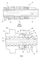
- a ball screw actuator includes an input member in the form of a drive shaft 30 of tubular form which is arranged to be rotated, in use, by an appropriate motor (not shown) through a suitable gearing arrangement.
- the input shaft 30 is provided, on its outer surface, with a helical groove defining a first screw thread formation 32 within which a plurality of spherical members or balls 34 (only one of which is shown) is received.
- the input shaft 30 is secured, in use, to a part of an aircraft such that the shaft 30 is free to rotate but cannot move in an axial direction, or such that axial movement is limited.
- the input shaft 30 carries a primary output member in the form of a nut 36 which is non-rotatably mounted upon a part of the aircraft frame through a dog 40.
- the primary nut 36 is provided with a second screw thread formation 38 which cooperates with the first screw thread formation 32 provided on the input shaft 30 to define, together with the balls 34, a high efficiency, low friction ball screw coupling between the input shaft 12 and the primary nut 36.
- the primary nut 36 includes a flanged region 36a which is secured, in use, to a linkage (not shown) in connection with the horizontal stabiliser.
- the input shaft 30 also carries a secondary nut arrangement, referred to generally as 42, comprising a non-rotatable nut housing 44 including a flange or spigot 44a which is coupled to the horizontal stabiliser.
- the nut housing 44 may also be coupled to the primary nut 36 such that it is axially movable with the nut 36 upon rotation of the input shaft 30.
- the nut housing 44 may be coupled to the structure of the aircraft. It is important that the primary and secondary load paths are separate and that the secondary load path should be unloaded in normal operating conditions.
- the secondary nut arrangement 42 also includes first and second nuts, 46, 48 respectively, the first and second nuts 46, 48 being provided with third and fourth screw thread formations 47, 49 respectively which are co-operable with the screw thread formation 32 provided on the input shaft 30 to provide relatively high friction screw thread couplings between the input shaft 30 and the secondary nut arrangement 42.
- the first nut 46 is coupled to the nut housing 44 through a dog 50 and is accurately positioned such that, in normal use, the first nut 46 adopts an equilibrium position (as shown in Figure 2), in which a narrow clearance is maintained between each of the third and fourth screw thread formations 47, 49 and the first screw thread formation 32 on the input shaft 30.
- the dog 50 ensures relative angular movement between the first nut 46 and the nut housing 44 is prevented, but permits a small degree of axial movement between these components.
- the second nut 48 is arranged such that it is free to rotate relative to both the first nut 46 and the nut housing 44 in the event that an angular load is applied to the second nut 48.
- a plurality of spherical drive members 54 are located between the first and second nuts 46, 48, the spherical drive members 54 being located within respective recesses or grooves (not visible in Figure 2) defined by opposing surfaces of the first and second nuts 46, 48.
- the recesses provided in the first and second nuts 46, 48 define ramped surfaces 56, 58 with which the drive members 54 are engageable.
- a spring assembly 52 is provided which acts on the first nut 46 and serves to retain the drive members 54 in their equilibrium positions within their respective recesses.
- the first and second nuts 46, 48 are free to translate along the screw thread formation 32 upon rotation of the input shaft 30.
- the ball screw coupling between the input shaft 30 and the primary nut 36 forms a much lower friction coupling than the screw thread couplings between the input shaft 30 and the first nut 46, and between the input shaft 30 and the second nut 48.
- the actuator When the actuator is in the normal operating condition substantially all of the angular load imparted by the input shaft 30 is taken up by the primary nut 36.
- the primary nut 36 moves axially along the input shaft 30, together with the nut housing 44, drive is imparted to the first nut 46, and hence the second nut 48, through the drive dog 50 such that the first and second nuts 46, 48 translate along the first screw thread formation 32 on the input shaft 30.
- there is substantially no frictional loading of the second nut 48 such that the second nut 48 is not caused to rotate.
- the load imparted by the input shaft 30, either tensile or compressive is transferred to the screw thread coupling and, hence, is transferred to the secondary nut arrangement 42 through the first and second nuts 46, 48.
- the first nut 46 is coupled to the non-rotatably mounted housing 44, the first nut 46 cannot rotate as angular load is taken up by the screw thread couplings, but the second nut 48 is free to rotate relative to the input shaft 30 such that the screw thread formation 49 provided on the second nut 48 is urged into contact with the screw thread formation 32, as shown in Figure 4, at points A and B.
- Frictional contact between the fourth screw thread formation 49 on the second nut 48 and the first screw thread formation 32 on the input shaft 30 applies a load to the second nut 48 which acts against the biasing force of the spring assembly 52, thereby urging the drive members 54 to ride up their respective ramped surfaces 56, 58, out of engagement with their respective recesses.
- axial movement is imparted to the first nut 46 relative to the second nut 48 and, hence, the third screw thread formation 47 provided on the first nut 46 is urged into contact with the screw thread formation 32 on the input shaft 30 at point C, as shown in Figure 5.
- the first and second nuts 46, 48 are locked onto the screw thread formation 32 on the input shaft 30 causing the actuator to be stalled and preventing further axial movement of the nut housing 44 and, hence, of the aircraft stabiliser.
- the first and second nuts 46, 48 should be formed from a material which provides a relatively high frictional force when their respective screw thread formations 47, 49 are urged into engagement with the screw thread formation 32 on the input shaft 30.
- Figure 6 shows a preferred embodiment of the invention in which the second nut 48 includes a flange 48 a having an end face 48 b which is arranged to engage a surface of the nut housing 44.
- the coefficient of friction between the surface 48 b and the surface of the nut housing 44 is relatively low to ensure that, even when the drive members 54 urge the first and second nuts 46, 48 apart, relative angular movement is permitted between the second nut 48 and the housing 44.
- the surface 48 b and/or the facing surface of the nut housing 44 may be provided with a suitable anti-friction coating.
- the embodiment shown in Figure 6 provides an advantage over that shown in Figures 4 and 5 in that the load imparted to the secondary nut arrangement 42 upon failure of the ball screw coupling is transferred directly to the nut housing 44 through the second nut 48, rather than being transferred through the first nut 46 also.
- Figure 7 shows an alternative configuration of the secondary nut arrangement 42 in accordance with a further embodiment of the invention.
- relative angular movement of both the first and second nuts 46, 48 of the secondary nut arrangement 42 relative to the housing 44 is permitted in conditions in which the ball screw coupling between the input shaft 30 and the primary nut 36 fails.
- the position of the first and second nuts 46, 48 relative to the input shaft 30 is under the control of a roller arrangement including a roller 60 and a pin 62.
- the roller 60 is engaged between radially outer surfaces of the first and second nuts 46, 48 and a part threaded, radially inner surface 45 of the housing 44 having a helix angle of substantially zero.
- the outer surface of the roller 60 also has a thread with a helix angle of zero which co-operates with the identical thread on the surface 45 so that the roller 60 is freely rotatable in normal operation.
- the first and second nuts 46, 48 have opposing helical threads on their radially outer surfaces 46a, 48a which co-operate with the thread on the roller 60.
- the pin 62 is received within corresponding recesses or grooves 63, 64 provided in the housing 44 and the second nut 48 respectively and serves to aid fixed location of the two parts 44, 48 relative to one another in normal operating circumstances.
- the first and second nuts 46, 48 are maintained in position by the pin 62 which prevents rotational movement of the second nut 48 in relation to the nut housing 44. If a load is imparted to the secondary nut arrangement 42 through the first and second nuts 46, 48 due to failure of the ball screw coupling, the second nut 48 is caused to rotate by interaction with the input shaft 30, as described previously. Angular movement of the second nut 48 results in a force being applied to the pin 62 which causes it to shear.
- Shearing of the pin 62 allows the first and second nuts 46, 48 to rotate and co-operation between the thread on the surface 48a of the second nut 48 with the thread on the roller 60 also causes the roller 60 to rotate.
- Rotation of the roller 60 results in rotation of the first nut 46 and co-operation between the opposing helical threads on the first and second nuts 46, 48 with the thread on the roller 60 results in axial translation of the first and second nuts 46, 48 in opposite directions.
- This axial movement results in the third and fourth screw thread formations 47, 49 being urged into contact with the screw thread formation 32 on the input shaft 30 and prevents further axial movement of the nut housing 44, thereby causing the actuator to stall.
- a position sensor may be provided on the secondary nut arrangement 42, if required, to sense angular movement of the second nut 48 and/or axial movement of the first and/or second nuts 46, 48 in the event that the angular load applied by the input shaft 30 is transferred from the ball screw coupling of the primary nut 36 to the screw thread coupling of the secondary nut arrangement 42.
- the position sensor may take the form of an LVDT for sensing translation of the first nut 46 and/or the second nut 48, or may take the form of an RVDT for sensing angular movement of the second nut 48.
- a warning signal may be provided to the aircraft flight control deck to warn the pilot of actuator failure.
Landscapes
- Engineering & Computer Science (AREA)
- General Engineering & Computer Science (AREA)
- Mechanical Engineering (AREA)
- Transmission Devices (AREA)
- Valve Device For Special Equipments (AREA)
- Valve-Gear Or Valve Arrangements (AREA)
- Electrical Discharge Machining, Electrochemical Machining, And Combined Machining (AREA)
- Turning (AREA)
Applications Claiming Priority (2)
| Application Number | Priority Date | Filing Date | Title |
|---|---|---|---|
| GBGB0112984.0A GB0112984D0 (en) | 2001-05-30 | 2001-05-30 | Screw actuator |
| GB0112984 | 2001-05-30 |
Publications (3)
| Publication Number | Publication Date |
|---|---|
| EP1262688A2 true EP1262688A2 (de) | 2002-12-04 |
| EP1262688A3 EP1262688A3 (de) | 2004-08-04 |
| EP1262688B1 EP1262688B1 (de) | 2006-09-27 |
Family
ID=9915454
Family Applications (1)
| Application Number | Title | Priority Date | Filing Date |
|---|---|---|---|
| EP02253830A Expired - Lifetime EP1262688B1 (de) | 2001-05-30 | 2002-05-30 | Spindelantrieb |
Country Status (6)
| Country | Link |
|---|---|
| US (1) | US6685382B2 (de) |
| EP (1) | EP1262688B1 (de) |
| AT (1) | ATE340953T1 (de) |
| DE (1) | DE60214929T2 (de) |
| ES (1) | ES2273971T3 (de) |
| GB (1) | GB0112984D0 (de) |
Cited By (7)
| Publication number | Priority date | Publication date | Assignee | Title |
|---|---|---|---|---|
| FR2844326A1 (fr) * | 2002-09-11 | 2004-03-12 | Trw Sys Aeronautiques Civil | Verin a vis a moyen de blocage en cas de passage sur ecrou secondaire |
| EP1283384A3 (de) * | 2001-08-09 | 2004-08-11 | Smiths Wolverhampton Limited | Sicherungsmutter für eine Kugelumlaufspindel |
| FR2865254A1 (fr) * | 2004-01-21 | 2005-07-22 | Goodrich Actuation Systems | Dispositif de detection de transfert de charge par cisaillement d'un pion ruptible |
| EP1467124A3 (de) * | 2003-04-11 | 2006-06-07 | Umbra Cuscinetti S.p.A. | Kugelspindelantrieb für Flugzeugsteuerflächen |
| EP1619413A3 (de) * | 2004-07-23 | 2007-12-12 | Jürgen Zimmermann | Stelleinrichtung |
| FR2970464A1 (fr) * | 2011-01-19 | 2012-07-20 | Goodrich Actuation Systems Sas | Perfectionnements aux actionneurs de commande de vol a ecrou secondaire |
| EP3282146B1 (de) * | 2016-08-12 | 2021-06-30 | Ratier-Figeac SAS | Sekundärlastpfaddetektion |
Families Citing this family (22)
| Publication number | Priority date | Publication date | Assignee | Title |
|---|---|---|---|---|
| GB0422134D0 (en) * | 2004-10-06 | 2004-11-03 | Goodrich Actuation Systems Ltd | Screw actuator |
| WO2007102558A1 (ja) * | 2006-03-08 | 2007-09-13 | Nsk Ltd. | 送りねじ機構及びステアリング装置 |
| US8545178B2 (en) * | 2006-03-08 | 2013-10-01 | Hamilton Sundstrand Corporation | Controlled propeller pitch lock actuation system |
| US8267656B2 (en) * | 2006-03-08 | 2012-09-18 | Hamilton Sundstrand Corporation | Propeller pitch lock system |
| FR2916023B1 (fr) * | 2007-05-11 | 2009-08-21 | Goodrich Actuation Systems Sas | Liaison mecanique fusible entre deux ecrous sur un ensemble a vis de securite a defaillance. |
| FR2938893B1 (fr) * | 2008-11-25 | 2011-07-15 | Innovation Technologie Conseil Itc | Actionneur lineaire |
| DE102009016797B4 (de) * | 2009-04-07 | 2022-11-24 | Liebherr-Aerospace Lindenberg Gmbh | Spindelaktuator |
| WO2010134078A1 (en) * | 2009-05-18 | 2010-11-25 | Orthogon Technologies 2003 | An intramedullary nail device |
| DE102009022404A1 (de) * | 2009-05-25 | 2010-12-02 | Liebherr-Aerospace Lindenberg Gmbh | Spindeltrieb |
| DE102009045857A1 (de) * | 2009-10-20 | 2011-04-21 | Robert Bosch Gmbh | Verfahren zur Herstellung einer Spindel für einen Spindeltrieb, Wälzgewindetrieb mit einer solchen Spindel und Verwendung des Wälzgewindetriebs |
| JP5756304B2 (ja) * | 2011-02-22 | 2015-07-29 | ミネベア株式会社 | リニアアクチュエータ |
| DE102011086674A1 (de) * | 2011-11-18 | 2013-05-23 | Rolls-Royce Deutschland Ltd & Co Kg | Lagervorrichtung und Turbomaschine mit Lagervorrichtung |
| US20150096396A1 (en) * | 2013-10-07 | 2015-04-09 | National Chung Cheng University | Ball scrw capable of sensing parallelism in real time |
| FR3016607B1 (fr) * | 2014-01-20 | 2016-01-22 | Sagem Defense Securite | Actionneur de commande d'un plan horizontal de stabilisation d'un aeronef |
| EP3072809B1 (de) * | 2015-03-27 | 2020-07-15 | Goodrich Actuation Systems SAS | Untere befestigung für einen trimmbaren horizontalen stabilisatoraktuator |
| WO2017125890A1 (en) * | 2016-01-20 | 2017-07-27 | Eaton Corporation | Ball screw with secondary lead for failure detection |
| DE102016223978A1 (de) | 2016-12-01 | 2018-06-07 | Schaeffler Technologies AG & Co. KG | Spindeltrieb mit Arretierung |
| US10583917B2 (en) * | 2017-05-18 | 2020-03-10 | Goodrich Corporation | Electromechanical actuator disconnect |
| EP3789294B1 (de) * | 2019-09-04 | 2023-05-03 | Goodrich Actuation Systems SAS | Aktuator |
| EP3809034B1 (de) * | 2019-10-17 | 2024-02-07 | Ratier-Figeac SAS | Schmierungssystem |
| IT202200020793A1 (it) * | 2022-10-10 | 2024-04-10 | Umbragroup S P A | Attuatore elettromeccanico lineare perfezionato |
| EP4497676A1 (de) * | 2023-07-27 | 2025-01-29 | Ratier-Figeac SAS | Anordnung für ein flugzeug |
Family Cites Families (7)
| Publication number | Priority date | Publication date | Assignee | Title |
|---|---|---|---|---|
| US3141349A (en) * | 1962-09-17 | 1964-07-21 | Cincinnati Milling Machine Co | Ball bearing screw and nut mechanism |
| DE2906172C2 (de) * | 1979-02-17 | 1984-04-12 | Gebr. Hofmann Gmbh & Co Kg Maschinenfabrik, 6100 Darmstadt | Sicherheitseinrichtung für eine spindelbetriebene Hebeeinrichtung, insbesondere Zwei-Säulen-Kraftfahrzeug-Hebebühne |
| US4644811A (en) * | 1985-06-19 | 1987-02-24 | The United States Of America As Represented By The Secretary Of The Air Force | Termination load carrying device |
| US5092539A (en) * | 1989-10-13 | 1992-03-03 | Bell Helicopter Textron Inc. | Jam resistant ball screw actuator |
| DE19740208C2 (de) * | 1997-09-12 | 1999-07-22 | Fraunhofer Ges Forschung | Antriebsvorrichtung für mehrere Aggregate einer Drehmaschine |
| GB9911150D0 (en) * | 1999-05-14 | 1999-07-14 | Lucas Ind Plc | Screw actuator |
| EP1283384A3 (de) * | 2001-08-09 | 2004-08-11 | Smiths Wolverhampton Limited | Sicherungsmutter für eine Kugelumlaufspindel |
-
2001
- 2001-05-30 GB GBGB0112984.0A patent/GB0112984D0/en not_active Ceased
-
2002
- 2002-05-29 US US10/157,170 patent/US6685382B2/en not_active Expired - Lifetime
- 2002-05-30 AT AT02253830T patent/ATE340953T1/de not_active IP Right Cessation
- 2002-05-30 EP EP02253830A patent/EP1262688B1/de not_active Expired - Lifetime
- 2002-05-30 DE DE60214929T patent/DE60214929T2/de not_active Expired - Lifetime
- 2002-05-30 ES ES02253830T patent/ES2273971T3/es not_active Expired - Lifetime
Non-Patent Citations (1)
| Title |
|---|
| None |
Cited By (11)
| Publication number | Priority date | Publication date | Assignee | Title |
|---|---|---|---|---|
| EP1283384A3 (de) * | 2001-08-09 | 2004-08-11 | Smiths Wolverhampton Limited | Sicherungsmutter für eine Kugelumlaufspindel |
| US6928895B2 (en) * | 2001-08-09 | 2005-08-16 | Smiths Wolverhampton Limited | Ballscrew locking nut |
| FR2844326A1 (fr) * | 2002-09-11 | 2004-03-12 | Trw Sys Aeronautiques Civil | Verin a vis a moyen de blocage en cas de passage sur ecrou secondaire |
| EP1398541A1 (de) * | 2002-09-11 | 2004-03-17 | Goodrich Actuation Systems | Spindelantrieb mit klemmender Vorrichtung beim belasten der zweiten Mutter |
| EP1467124A3 (de) * | 2003-04-11 | 2006-06-07 | Umbra Cuscinetti S.p.A. | Kugelspindelantrieb für Flugzeugsteuerflächen |
| FR2865254A1 (fr) * | 2004-01-21 | 2005-07-22 | Goodrich Actuation Systems | Dispositif de detection de transfert de charge par cisaillement d'un pion ruptible |
| EP1557588A1 (de) * | 2004-01-21 | 2005-07-27 | Goodrich Actuation Systems SAS | Detektionvorrichtung zur Lastübertragung mit einem Scherstift |
| EP1619413A3 (de) * | 2004-07-23 | 2007-12-12 | Jürgen Zimmermann | Stelleinrichtung |
| FR2970464A1 (fr) * | 2011-01-19 | 2012-07-20 | Goodrich Actuation Systems Sas | Perfectionnements aux actionneurs de commande de vol a ecrou secondaire |
| WO2012098206A1 (fr) * | 2011-01-19 | 2012-07-26 | Goodrich Actuation Systems Sas | Perfectionnements aux actionneurs de commande de vol a ecrou secondaire |
| EP3282146B1 (de) * | 2016-08-12 | 2021-06-30 | Ratier-Figeac SAS | Sekundärlastpfaddetektion |
Also Published As
| Publication number | Publication date |
|---|---|
| EP1262688B1 (de) | 2006-09-27 |
| DE60214929T2 (de) | 2007-09-06 |
| GB0112984D0 (en) | 2001-07-18 |
| DE60214929D1 (de) | 2006-11-09 |
| US20020182006A1 (en) | 2002-12-05 |
| EP1262688A3 (de) | 2004-08-04 |
| ES2273971T3 (es) | 2007-05-16 |
| ATE340953T1 (de) | 2006-10-15 |
| US6685382B2 (en) | 2004-02-03 |
Similar Documents
| Publication | Publication Date | Title |
|---|---|---|
| EP1262688B1 (de) | Spindelantrieb | |
| US8393568B2 (en) | Enhanced lubrication skewed roller clutch assembly and actuator including same | |
| US6672540B1 (en) | Actuator for aircraft stabilizers with a failure responsive lock control mechanism | |
| US10760528B2 (en) | Thrust reverser actuation | |
| US6202803B1 (en) | Output load limiter | |
| CN110382916B (zh) | 配备有不能返回禁止区域的系统的致动器 | |
| US20130001357A1 (en) | Horizontal stabilizer trim actuator failure detection system and method using position sensors | |
| CA2734341C (en) | Cone brake no-back | |
| US10844938B2 (en) | Actuator | |
| US10974846B2 (en) | Fixed end electronic detection of secondary load path engagement of aircraft flight control actuator | |
| JP6244021B2 (ja) | 出力トルクに反応可能なトルク制限器 | |
| US11964751B2 (en) | Aircraft actuator with no-back, load detent assembly | |
| US12559226B2 (en) | Assembly for an aircraft | |
| US4628752A (en) | Actuators and actuator assemblies | |
| EP3751172A1 (de) | Untere aktuatorbefestigung | |
| EP2285673B1 (de) | Verfahren zur bestimmung der augenscheinlichen betriebsintegrität einer rückdrehsicherung | |
| US12540659B2 (en) | Screw actuators | |
| US20240190403A1 (en) | Braking device | |
| US12553499B2 (en) | Linear actuator |
Legal Events
| Date | Code | Title | Description |
|---|---|---|---|
| PUAI | Public reference made under article 153(3) epc to a published international application that has entered the european phase |
Free format text: ORIGINAL CODE: 0009012 |
|
| AK | Designated contracting states |
Kind code of ref document: A2 Designated state(s): AT BE CH CY DE DK ES FI FR GB GR IE IT LI LU MC NL PT SE TR |
|
| AX | Request for extension of the european patent |
Free format text: AL;LT;LV;MK;RO;SI |
|
| RAP1 | Party data changed (applicant data changed or rights of an application transferred) |
Owner name: GOODRICH ACTUATION SYSTEMS LTD |
|
| PUAL | Search report despatched |
Free format text: ORIGINAL CODE: 0009013 |
|
| AK | Designated contracting states |
Kind code of ref document: A3 Designated state(s): AT BE CH CY DE DK ES FI FR GB GR IE IT LI LU MC NL PT SE TR |
|
| AX | Request for extension of the european patent |
Extension state: AL LT LV MK RO SI |
|
| RIC1 | Information provided on ipc code assigned before grant |
Ipc: 7F 16H 25/22 A Ipc: 7F 16H 25/24 B |
|
| 17P | Request for examination filed |
Effective date: 20050118 |
|
| AKX | Designation fees paid |
Designated state(s): AT BE CH CY DE DK ES FI FR GB GR IE IT LI LU MC NL PT SE TR |
|
| GRAP | Despatch of communication of intention to grant a patent |
Free format text: ORIGINAL CODE: EPIDOSNIGR1 |
|
| GRAS | Grant fee paid |
Free format text: ORIGINAL CODE: EPIDOSNIGR3 |
|
| GRAA | (expected) grant |
Free format text: ORIGINAL CODE: 0009210 |
|
| RAP1 | Party data changed (applicant data changed or rights of an application transferred) |
Owner name: GOODRICH ACTUATION SYSTEMS SAS |
|
| AK | Designated contracting states |
Kind code of ref document: B1 Designated state(s): AT BE CH CY DE DK ES FI FR GB GR IE IT LI LU MC NL PT SE TR |
|
| PG25 | Lapsed in a contracting state [announced via postgrant information from national office to epo] |
Ref country code: AT Free format text: LAPSE BECAUSE OF FAILURE TO SUBMIT A TRANSLATION OF THE DESCRIPTION OR TO PAY THE FEE WITHIN THE PRESCRIBED TIME-LIMIT Effective date: 20060927 Ref country code: IT Free format text: LAPSE BECAUSE OF FAILURE TO SUBMIT A TRANSLATION OF THE DESCRIPTION OR TO PAY THE FEE WITHIN THE PRESCRIBED TIME-LIMIT;WARNING: LAPSES OF ITALIAN PATENTS WITH EFFECTIVE DATE BEFORE 2007 MAY HAVE OCCURRED AT ANY TIME BEFORE 2007. THE CORRECT EFFECTIVE DATE MAY BE DIFFERENT FROM THE ONE RECORDED. Effective date: 20060927 Ref country code: CH Free format text: LAPSE BECAUSE OF FAILURE TO SUBMIT A TRANSLATION OF THE DESCRIPTION OR TO PAY THE FEE WITHIN THE PRESCRIBED TIME-LIMIT Effective date: 20060927 Ref country code: BE Free format text: LAPSE BECAUSE OF FAILURE TO SUBMIT A TRANSLATION OF THE DESCRIPTION OR TO PAY THE FEE WITHIN THE PRESCRIBED TIME-LIMIT Effective date: 20060927 Ref country code: NL Free format text: LAPSE BECAUSE OF FAILURE TO SUBMIT A TRANSLATION OF THE DESCRIPTION OR TO PAY THE FEE WITHIN THE PRESCRIBED TIME-LIMIT Effective date: 20060927 Ref country code: LI Free format text: LAPSE BECAUSE OF FAILURE TO SUBMIT A TRANSLATION OF THE DESCRIPTION OR TO PAY THE FEE WITHIN THE PRESCRIBED TIME-LIMIT Effective date: 20060927 Ref country code: FI Free format text: LAPSE BECAUSE OF FAILURE TO SUBMIT A TRANSLATION OF THE DESCRIPTION OR TO PAY THE FEE WITHIN THE PRESCRIBED TIME-LIMIT Effective date: 20060927 |
|
| REG | Reference to a national code |
Ref country code: GB Ref legal event code: FG4D |
|
| REG | Reference to a national code |
Ref country code: CH Ref legal event code: EP |
|
| REG | Reference to a national code |
Ref country code: IE Ref legal event code: FG4D |
|
| REF | Corresponds to: |
Ref document number: 60214929 Country of ref document: DE Date of ref document: 20061109 Kind code of ref document: P |
|
| PG25 | Lapsed in a contracting state [announced via postgrant information from national office to epo] |
Ref country code: SE Free format text: LAPSE BECAUSE OF FAILURE TO SUBMIT A TRANSLATION OF THE DESCRIPTION OR TO PAY THE FEE WITHIN THE PRESCRIBED TIME-LIMIT Effective date: 20061227 Ref country code: DK Free format text: LAPSE BECAUSE OF FAILURE TO SUBMIT A TRANSLATION OF THE DESCRIPTION OR TO PAY THE FEE WITHIN THE PRESCRIBED TIME-LIMIT Effective date: 20061227 |
|
| NLV1 | Nl: lapsed or annulled due to failure to fulfill the requirements of art. 29p and 29m of the patents act | ||
| PG25 | Lapsed in a contracting state [announced via postgrant information from national office to epo] |
Ref country code: PT Free format text: LAPSE BECAUSE OF FAILURE TO SUBMIT A TRANSLATION OF THE DESCRIPTION OR TO PAY THE FEE WITHIN THE PRESCRIBED TIME-LIMIT Effective date: 20070313 |
|
| REG | Reference to a national code |
Ref country code: CH Ref legal event code: PL |
|
| ET | Fr: translation filed | ||
| REG | Reference to a national code |
Ref country code: ES Ref legal event code: FG2A Ref document number: 2273971 Country of ref document: ES Kind code of ref document: T3 |
|
| PLBE | No opposition filed within time limit |
Free format text: ORIGINAL CODE: 0009261 |
|
| STAA | Information on the status of an ep patent application or granted ep patent |
Free format text: STATUS: NO OPPOSITION FILED WITHIN TIME LIMIT |
|
| 26N | No opposition filed |
Effective date: 20070628 |
|
| PG25 | Lapsed in a contracting state [announced via postgrant information from national office to epo] |
Ref country code: MC Free format text: LAPSE BECAUSE OF NON-PAYMENT OF DUE FEES Effective date: 20070531 |
|
| PG25 | Lapsed in a contracting state [announced via postgrant information from national office to epo] |
Ref country code: GR Free format text: LAPSE BECAUSE OF FAILURE TO SUBMIT A TRANSLATION OF THE DESCRIPTION OR TO PAY THE FEE WITHIN THE PRESCRIBED TIME-LIMIT Effective date: 20061228 |
|
| PG25 | Lapsed in a contracting state [announced via postgrant information from national office to epo] |
Ref country code: IE Free format text: LAPSE BECAUSE OF NON-PAYMENT OF DUE FEES Effective date: 20070530 |
|
| PG25 | Lapsed in a contracting state [announced via postgrant information from national office to epo] |
Ref country code: CY Free format text: LAPSE BECAUSE OF FAILURE TO SUBMIT A TRANSLATION OF THE DESCRIPTION OR TO PAY THE FEE WITHIN THE PRESCRIBED TIME-LIMIT Effective date: 20060927 Ref country code: LU Free format text: LAPSE BECAUSE OF NON-PAYMENT OF DUE FEES Effective date: 20070530 |
|
| PG25 | Lapsed in a contracting state [announced via postgrant information from national office to epo] |
Ref country code: TR Free format text: LAPSE BECAUSE OF FAILURE TO SUBMIT A TRANSLATION OF THE DESCRIPTION OR TO PAY THE FEE WITHIN THE PRESCRIBED TIME-LIMIT Effective date: 20060927 |
|
| REG | Reference to a national code |
Ref country code: FR Ref legal event code: PLFP Year of fee payment: 15 |
|
| REG | Reference to a national code |
Ref country code: FR Ref legal event code: PLFP Year of fee payment: 16 |
|
| REG | Reference to a national code |
Ref country code: FR Ref legal event code: PLFP Year of fee payment: 17 |
|
| PGFP | Annual fee paid to national office [announced via postgrant information from national office to epo] |
Ref country code: DE Payment date: 20210421 Year of fee payment: 20 Ref country code: FR Payment date: 20210421 Year of fee payment: 20 Ref country code: IT Payment date: 20210422 Year of fee payment: 20 |
|
| PGFP | Annual fee paid to national office [announced via postgrant information from national office to epo] |
Ref country code: ES Payment date: 20210601 Year of fee payment: 20 Ref country code: GB Payment date: 20210422 Year of fee payment: 20 |
|
| REG | Reference to a national code |
Ref country code: DE Ref legal event code: R071 Ref document number: 60214929 Country of ref document: DE |
|
| REG | Reference to a national code |
Ref country code: GB Ref legal event code: PE20 Expiry date: 20220529 |
|
| REG | Reference to a national code |
Ref country code: ES Ref legal event code: FD2A Effective date: 20220706 |
|
| PG25 | Lapsed in a contracting state [announced via postgrant information from national office to epo] |
Ref country code: GB Free format text: LAPSE BECAUSE OF EXPIRATION OF PROTECTION Effective date: 20220529 Ref country code: ES Free format text: LAPSE BECAUSE OF EXPIRATION OF PROTECTION Effective date: 20220531 |