EP1262696B1 - Dichtungsanordnung für Turbomaschinenlager - Google Patents
Dichtungsanordnung für Turbomaschinenlager Download PDFInfo
- Publication number
- EP1262696B1 EP1262696B1 EP01870114A EP01870114A EP1262696B1 EP 1262696 B1 EP1262696 B1 EP 1262696B1 EP 01870114 A EP01870114 A EP 01870114A EP 01870114 A EP01870114 A EP 01870114A EP 1262696 B1 EP1262696 B1 EP 1262696B1
- Authority
- EP
- European Patent Office
- Prior art keywords
- ring
- support
- carbon ring
- bearing
- segmented
- Prior art date
- Legal status (The legal status is an assumption and is not a legal conclusion. Google has not performed a legal analysis and makes no representation as to the accuracy of the status listed.)
- Expired - Lifetime
Links
Images


Classifications
-
- F—MECHANICAL ENGINEERING; LIGHTING; HEATING; WEAPONS; BLASTING
- F16—ENGINEERING ELEMENTS AND UNITS; GENERAL MEASURES FOR PRODUCING AND MAINTAINING EFFECTIVE FUNCTIONING OF MACHINES OR INSTALLATIONS; THERMAL INSULATION IN GENERAL
- F16J—PISTONS; CYLINDERS; SEALINGS
- F16J15/00—Sealings
- F16J15/44—Free-space packings
- F16J15/441—Free-space packings with floating ring
- F16J15/442—Free-space packings with floating ring segmented
-
- F—MECHANICAL ENGINEERING; LIGHTING; HEATING; WEAPONS; BLASTING
- F16—ENGINEERING ELEMENTS AND UNITS; GENERAL MEASURES FOR PRODUCING AND MAINTAINING EFFECTIVE FUNCTIONING OF MACHINES OR INSTALLATIONS; THERMAL INSULATION IN GENERAL
- F16J—PISTONS; CYLINDERS; SEALINGS
- F16J15/00—Sealings
- F16J15/16—Sealings between relatively-moving surfaces
- F16J15/34—Sealings between relatively-moving surfaces with slip-ring pressed against a more or less radial face on one member
- F16J15/3404—Sealings between relatively-moving surfaces with slip-ring pressed against a more or less radial face on one member and characterised by parts or details relating to lubrication, cooling or venting of the seal
- F16J15/3408—Sealings between relatively-moving surfaces with slip-ring pressed against a more or less radial face on one member and characterised by parts or details relating to lubrication, cooling or venting of the seal at least one ring having an uneven slipping surface
- F16J15/3412—Sealings between relatively-moving surfaces with slip-ring pressed against a more or less radial face on one member and characterised by parts or details relating to lubrication, cooling or venting of the seal at least one ring having an uneven slipping surface with cavities
- F16J15/342—Sealings between relatively-moving surfaces with slip-ring pressed against a more or less radial face on one member and characterised by parts or details relating to lubrication, cooling or venting of the seal at least one ring having an uneven slipping surface with cavities with means for feeding fluid directly to the face
Definitions
- the present invention relates to a seal seal for a turbomachine bearing.
- gaskets for turbomachine bearing housings that include a bearing mounted between a sleeve integral with a shaft, a bearing bracket, a seal bracket and which serve to delimit the oil chamber of the bearing of the enclosure to Air turbomachine, is well known in itself. It exists essentially two types of such joints, on the one hand radial seals, with or without contact, and on the other hand axial joints.
- the present invention aims at enabling solve the problems of the state of the art.
- the present invention aims to enable the control of air leaks from the air chamber to the oil chamber while preventing oil leakage from the oil chamber to the air enclosure does not produce and this regardless of the configurations of theft, even in case of reverse pressure.
- the present invention further aims to allow the control of the heating of the joints by the friction and therefore reduce wear.
- the present invention aims to enable a solution that allows to increase the service life of such joints.
- the present invention therefore aims to propose the use of segmented axial carbon seals having a lift in a turbomachine bearing which to solve the various problems of the state of the technique.
- the present invention relates to a seal device for a bearing turbomachine which comprises a bearing mounted on a sleeve attached to a tree, as well as a bearing support, a seal support, said bearing for separating the oil chamber of the bearing of an air chamber of the turbomachine, said seal device comprising a support, a rotating ring mounted on the part of the sleeve located on the side of the oil chamber, a carbon ring segmentation allowing the injection of parietal air between junctions of successive segments of the carbon ring, a axial locking system and anti-rotation of the ring of carbon allowing this carbon ring to stay on its support in the free state and in operation, said locking system not having contact with the tree and with the support, the segmented carbon ring being pressed axially in the free state against the ring rotating by springs and presenting on their face radial a cooperative parietal air injection system with the ring rotating by the radial face, the ring rotating cooperating with the segments of the carbon ring
- a semi-static seal is obtained by compressing the segments of the ring of carbon against the support using at least one spring of circular expansion housed in a groove, this semi-static sealing being machined directly on the segmented carbon ring.
- the rotating ring is held axially by a spring in Belle Ville type ring, centered on the sleeve using Belle's Spring Compression Control System City through an elastic seal, this ring rotating being driven in rotation by pins of a antirotation and axial locking system ensures the blocking of this carbon ring in the free state.
- the embodiments described above allow the realization of a parietal injection of air through the junction of segments to promote the lift effect.
- the present invention will advantageously also to support displacements axial or radial of the tree.
- the present invention allows very specific uses like applications to very high or very low temperatures Cryogenic).
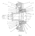
- FIG. 1 represents, according to a view in cut, by a plane passing through the axis of rotation of the shaft, a turbomachine bearing part comprising a sealing device according to the invention
- Figure 2 shows a front view enlarged segmented carbon ring for static seals
- Fig 3 shows a view from the back enlarged segmented carbon ring for static seals
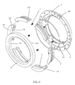
- FIG. 4 represents an exploded view of the segmented axial carbon seal with lift and injection parietal according to the present invention.
- Figure 1 represents a bearing in which we represent a casing (1) or support of the static part of the seal with holes (24) for discharging particles, a ring of carbon (2) segmented with tiered overlap and injection of parietal air, an axial locking system and antirotation (6) which allows the carbon ring (2) to remain in his support (1) in the free state and in functioning, a rotating ring (3) carbide or coated of carbide with grooves generating a lift effect on the contact surface (19) cooperating with the surface (20) of the segmented carbon ring (2).
- the rotating ring (3) is centered but not fixed on a sleeve (15), which is fixed on the shaft (16), to by means of an elastic seal (5) allowing non-centering tightening of the rotating ring (3) and resistant to operating temperatures.
- the whole is in front a bearing (8) itself is mounted on a support (10).
- the rotating ring (3) is driven by anti-rotation locking pins (12) and is maintained only in axial displacement by a ring spring (4) for example Belle Ville type and a system of cartridges controlled compression (9) to ensure proper compression of the ring spring (4).
- a ring spring (4) for example Belle Ville type and a system of cartridges controlled compression (9) to ensure proper compression of the ring spring (4).
- Axial load to maintain contact between the segmented carbon ring (2) and the rotating ring (3) in the free state is obtained by the application of axial springs (7).
- This static seal is provided by a circular expansion spring (21) housed in a groove (23) which makes contact between the ring of carbon (2) segmented and the support of the joint (1).
- An air chamber (18) ensures the air-side pressurization of the segmented carbon ring (2) and an oil chamber (17) provides pressure on the oil side of the landing.
- a seal support (11) secures the attachment of the envelope (1) or support with a setting of compression of the carbon ring (2) segmented by the presence of a wedge (25) and thus separates the air chamber (18) of the oil chamber (17).
Landscapes
- Engineering & Computer Science (AREA)
- General Engineering & Computer Science (AREA)
- Mechanical Engineering (AREA)
- Mechanical Sealing (AREA)
- Turbine Rotor Nozzle Sealing (AREA)
- Sealing Devices (AREA)
- Rolling Contact Bearings (AREA)
Claims (3)
- Dichtung für das Lager eines Turbotriebwerks, das ein Wälzlager (8) umfasst, das auf eine Muffe (15), die mit einer Welle (16) verbunden ist, montiert ist, sowie eine Lageraufnahme (10), eine Dichtungsaufnahme (11), wobei das besagte Lager es ermöglicht, den Ölraum (17) des Wälzlagers von einem Luftraum (18) eines Turbotriebwerks zu trennen; die besagte Dichtung umfasst eine Aufnahme (1), einen Drehring (3), der auf den auf der Ölraumseite (17) befindlichen Teil der Muffe (15) montiert werden kann, gekennzeichnet durch einen segmentierten Kohlering (2), der das Einblasen von Luft am Umfang durch Verbindungsstellen (14) zwischen den aufeinander folgenden Kohleringsegmenten (2) ermöglicht, ein System zur axialen Sicherung (6) und Verdrehsicherung des segmentierten Kohlerings (2), durch das dieser segmentierte Kohlering (2) im freien Zustand und im Betrieb in seiner Aufnahme (1) gehalten werden kann; wobei das besagte Sicherungssystem (6) weder die Welle (16) noch die Aufnahme (1) berührt und der segmentierte Kohlering (2) im freien Zustand durch Federn (7) in axialer Richtung gegen den Drehring (3) gedrückt wird und auf seiner Radialseite (20) ein System zum Einblasen von Luft am Umfang aufweist, das mit dem Drehring (3) über dessen Radialseite (19) zusammenwirkt, wobei der Drehring (3) mit den Segmenten des Kohlerings (2) zusammenwirkt, so dass Tragnuten (13) erzeugt werden, die während des Betriebs eine dynamische Abdichtung ohne Reibung zwischen den Radialflächen (19, 20) gewährleisten.
- Dichtung nach Anspruch 1, dadurch gekennzeichnet, dass eine halbstatische Abdichtung (22) dadurch gewährleistet wird, dass die Segmente des Kohlerings (2) mittels einer kreisförmigen Dehnfeder (21), die in einer Nut (23) sitzt, gegen die Aufnahme (1) gepresst werden, wobei diese halbstatische Dichtung direkt in dem segmentierten Kohlering (2) hergestellt ist.
- Dichtung nach Anspruch 1 oder 2, dadurch gekennzeichnet, dass der Drehring (3) in axialer Richtung durch eine Ringfeder vom Typ Tellerfeder gehalten wird, die durch ein Kompressionsprüfsystem (9) der Tellerfeder mittels einer elastischen Dichtung (5) mittig auf der Muffe (15) gehalten wird, wobei dieser Drehring (3) durch Stifte (12) in Drehung versetzt wird.
Priority Applications (3)
| Application Number | Priority Date | Filing Date | Title |
|---|---|---|---|
| DE60113069T DE60113069T2 (de) | 2001-05-30 | 2001-05-30 | Dichtungsanordnung für Turbomaschinenlager |
| EP01870114A EP1262696B1 (de) | 2001-05-30 | 2001-05-30 | Dichtungsanordnung für Turbomaschinenlager |
| US10/158,205 US20020180156A1 (en) | 2001-05-30 | 2002-05-28 | Axial sealing device for a turbomachine bearing |
Applications Claiming Priority (1)
| Application Number | Priority Date | Filing Date | Title |
|---|---|---|---|
| EP01870114A EP1262696B1 (de) | 2001-05-30 | 2001-05-30 | Dichtungsanordnung für Turbomaschinenlager |
Publications (2)
| Publication Number | Publication Date |
|---|---|
| EP1262696A1 EP1262696A1 (de) | 2002-12-04 |
| EP1262696B1 true EP1262696B1 (de) | 2005-08-31 |
Family
ID=8184978
Family Applications (1)
| Application Number | Title | Priority Date | Filing Date |
|---|---|---|---|
| EP01870114A Expired - Lifetime EP1262696B1 (de) | 2001-05-30 | 2001-05-30 | Dichtungsanordnung für Turbomaschinenlager |
Country Status (3)
| Country | Link |
|---|---|
| US (1) | US20020180156A1 (de) |
| EP (1) | EP1262696B1 (de) |
| DE (1) | DE60113069T2 (de) |
Families Citing this family (13)
| Publication number | Priority date | Publication date | Assignee | Title |
|---|---|---|---|---|
| CN101749719B (zh) * | 2010-02-10 | 2012-03-07 | 无锡华光锅炉股份有限公司 | 一种锅炉用驱动连杆与风室间的密封装置 |
| WO2012022550A2 (de) * | 2010-07-21 | 2012-02-23 | Siemens Aktiengesellschaft | Dichteinrichtung |
| US8348280B2 (en) * | 2010-10-22 | 2013-01-08 | General Electric Company | Seal apparatus |
| US9534502B2 (en) * | 2014-03-26 | 2017-01-03 | General Electric Company | Individually compliant segments for split ring hydrodynamic face seal |
| WO2016055824A1 (en) * | 2014-10-07 | 2016-04-14 | Dresser Rand S.A. | Seal assembly for a turbomachine |
| JP2016114131A (ja) * | 2014-12-12 | 2016-06-23 | 三菱日立パワーシステムズ株式会社 | シール装置、回転機械、及びシール装置の製造方法 |
| US11371373B2 (en) | 2019-10-29 | 2022-06-28 | Raytheon Technologies Corporation | Seal assembly for use in gas turbine engines |
| CN112762173B (zh) * | 2021-01-18 | 2023-06-20 | 洛阳佰工工业密封有限公司 | 一种避免油封泄漏的机械密封组件结构 |
| CN113405735B (zh) * | 2021-04-30 | 2022-11-11 | 北京航天动力研究所 | 一种液体火箭发动机涡轮泵用高速氦气端面密封试验装置 |
| CN114087365B (zh) * | 2021-12-21 | 2024-09-03 | 江苏华青流体科技有限公司 | 一种刮板机用机械密封 |
| CN115585248A (zh) * | 2022-11-02 | 2023-01-10 | 贵州盘江精煤股份有限公司 | 一种高使用寿命破碎机减速箱 |
| CN119256762B (zh) * | 2023-07-07 | 2026-04-24 | 大连升隆机械有限公司 | 一种水稻收割机支重轮 |
| GB2635130A (en) * | 2023-10-30 | 2025-05-07 | Siemens Energy Global Gmbh & Co Kg | Seal assembly for gas turbine engine |
Family Cites Families (23)
| Publication number | Priority date | Publication date | Assignee | Title |
|---|---|---|---|---|
| US3347553A (en) * | 1966-05-23 | 1967-10-17 | Gen Electric | Fluid seal |
| US3575424A (en) * | 1969-11-28 | 1971-04-20 | Koppers Co Inc | Pressure balanced circumferential seal assembly |
| US3758179A (en) * | 1971-09-24 | 1973-09-11 | Basil Smith Seals Ltd | Mechanical shaft seal |
| US3874677A (en) | 1973-07-19 | 1975-04-01 | Nasa | High speed, self-acting shaft seal |
| US4213618A (en) * | 1978-05-24 | 1980-07-22 | Mechanical Seal & Service, Inc. | Self-contained rotary mechanical seals |
| US4285526A (en) * | 1979-09-25 | 1981-08-25 | Stefa Industri Aktiebolag | Sealing device for bearings, especially roll bearings |
| DE3119467C2 (de) | 1981-05-15 | 1983-09-01 | MTU Motoren- und Turbinen-Union München GmbH, 8000 München | Gleitringdichtung mit gasdynamischer Schmierung für hochtourige Strömungsmaschinen, insbesondere Gasturbinentriebwerke |
| US4578018A (en) * | 1983-06-20 | 1986-03-25 | General Electric Company | Rotor thrust balancing |
| US4687346A (en) * | 1986-09-02 | 1987-08-18 | United Technologies Corporation | Low profile bearing support structure |
| FR2644205B1 (fr) | 1989-03-08 | 1991-05-03 | Snecma | Palier de turbomachine a joint d'etancheite integre |
| US5058904A (en) * | 1990-02-21 | 1991-10-22 | Eg&G Sealol Inc. | Self-contained sealing ring assembly |
| FR2670830B1 (fr) | 1990-12-19 | 1994-12-02 | Snecma | Systeme d'etancheite pour palier d'une machine, notamment d'une turbomachine. |
| US5145189A (en) * | 1991-09-11 | 1992-09-08 | General Electric Company | Hydro-lift dynamic circumferential seal |
| US5301957A (en) * | 1992-04-27 | 1994-04-12 | General Electric Company | Expanding circumferential seal with upper-cooled runner |
| AU676466B2 (en) * | 1993-03-09 | 1997-03-13 | Robert Mconie | Flexible drive split mechanical seal |
| US5509664A (en) * | 1993-07-19 | 1996-04-23 | Stein Seal Company | Segmented hydrodynamic seals for sealing a rotatable shaft |
| US5516118A (en) * | 1993-07-19 | 1996-05-14 | Stein Seal Company | Circumferential hydrodynamic seals for sealing a bidirectionally rotatable member |
| US5813830A (en) | 1996-02-09 | 1998-09-29 | Allison Engine Company, Inc. | Carbon seal contaminant barrier system |
| US5820129A (en) * | 1996-07-11 | 1998-10-13 | Power Packing Co., Inc. | Mechanical split double seals |
| US6131912A (en) * | 1997-12-17 | 2000-10-17 | A.W. Chesterton Company | Split mechanical face seal |
| EP0967424B1 (de) | 1998-06-26 | 2004-03-17 | Techspace aero | Turbomachinenvorrichtung mit einer Dichtung |
| JP3650954B2 (ja) * | 1998-09-18 | 2005-05-25 | イーグル工業株式会社 | 高速用非接触型メカニカルシール |
| EP1055848B1 (de) | 1999-05-26 | 2004-08-25 | Techspace Aero | Dichtungsanordnung mit Auftrieb für Turbomaschinenlagergehäuse |
-
2001
- 2001-05-30 DE DE60113069T patent/DE60113069T2/de not_active Expired - Lifetime
- 2001-05-30 EP EP01870114A patent/EP1262696B1/de not_active Expired - Lifetime
-
2002
- 2002-05-28 US US10/158,205 patent/US20020180156A1/en not_active Abandoned
Also Published As
| Publication number | Publication date |
|---|---|
| EP1262696A1 (de) | 2002-12-04 |
| DE60113069T2 (de) | 2006-06-08 |
| US20020180156A1 (en) | 2002-12-05 |
| DE60113069D1 (de) | 2005-10-06 |
Similar Documents
| Publication | Publication Date | Title |
|---|---|---|
| EP1262696B1 (de) | Dichtungsanordnung für Turbomaschinenlager | |
| EP0967424B1 (de) | Turbomachinenvorrichtung mit einer Dichtung | |
| CA2552667C (en) | Tandem dual element intershaft carbon seal | |
| EP2870323A1 (de) | Dichtungsvorrichtung für das lager einer turbomaschine mit zwei elastischen dichtungen | |
| US5029875A (en) | Fluid seal structure | |
| FR2973440A1 (fr) | Garniture d'aspiration mecanique et procede associe | |
| EP0632218A1 (de) | Bürstendichtung mit schwimmenden Stützplatten | |
| EP1167788A1 (de) | Dichtung eines in ein Wälzlager integrierten Quetschfilmdämpfers | |
| FR2879649A1 (fr) | Supports de joint abrasables amovibles pour l'etancheite entre organes de turbine rotatifs et fixes. | |
| CA2094591A1 (en) | Sear rotor | |
| US5399024A (en) | Face seal with hydrodynamic thrust pads | |
| EP1055848B1 (de) | Dichtungsanordnung mit Auftrieb für Turbomaschinenlagergehäuse | |
| FR2602847A1 (fr) | Systeme d'etancheite pour arbre tournant dans un element support | |
| EP0500884A1 (de) | Dichtungsvorrichtung zwischen der zylinderkopf und zylinderrohre. | |
| EP1186813B1 (de) | Berührungsfreie Axialkohlenstoffdichtung für ein Lagergehäuse | |
| JPS6222030B2 (de) | ||
| EP1170520A2 (de) | Mit einem Quetschfilmdämpfer versehenes Wälzlager | |
| JP2006300191A (ja) | シール装置 | |
| FR2730276A1 (fr) | Garniture d'etancheite a anneau de glissement pour turbomachines, notamment des propulseurs a turbine a gaz | |
| EP1188972A1 (de) | Berührungsfreie Axialkohlenstoffdichtung für ein Lagergehäuse | |
| EP4374048B1 (de) | Auf einer niederdruckwelle in einer turbomaschine montierte hülse | |
| FR2638501A1 (fr) | Joint d'etancheite de bout d'arbre | |
| JP3367780B2 (ja) | 密封装置 | |
| RU1822914C (ru) | Уплотнение вала | |
| RU1827483C (ru) | Уплотнение вала турбокомпрессора |
Legal Events
| Date | Code | Title | Description |
|---|---|---|---|
| PUAI | Public reference made under article 153(3) epc to a published international application that has entered the european phase |
Free format text: ORIGINAL CODE: 0009012 |
|
| AK | Designated contracting states |
Kind code of ref document: A1 Designated state(s): AT BE CH CY DE DK ES FI FR GB GR IE IT LI LU MC NL PT SE TR |
|
| AX | Request for extension of the european patent |
Free format text: AL;LT;LV;MK;RO;SI |
|
| 17P | Request for examination filed |
Effective date: 20030317 |
|
| AKX | Designation fees paid |
Designated state(s): BE DE FR GB |
|
| GRAP | Despatch of communication of intention to grant a patent |
Free format text: ORIGINAL CODE: EPIDOSNIGR1 |
|
| GRAP | Despatch of communication of intention to grant a patent |
Free format text: ORIGINAL CODE: EPIDOSNIGR1 |
|
| GRAS | Grant fee paid |
Free format text: ORIGINAL CODE: EPIDOSNIGR3 |
|
| GRAA | (expected) grant |
Free format text: ORIGINAL CODE: 0009210 |
|
| AK | Designated contracting states |
Kind code of ref document: B1 Designated state(s): BE DE FR GB |
|
| REG | Reference to a national code |
Ref country code: GB Ref legal event code: FG4D Free format text: NOT ENGLISH |
|
| REF | Corresponds to: |
Ref document number: 60113069 Country of ref document: DE Date of ref document: 20051006 Kind code of ref document: P |
|
| GBT | Gb: translation of ep patent filed (gb section 77(6)(a)/1977) |
Effective date: 20050928 |
|
| PLBE | No opposition filed within time limit |
Free format text: ORIGINAL CODE: 0009261 |
|
| STAA | Information on the status of an ep patent application or granted ep patent |
Free format text: STATUS: NO OPPOSITION FILED WITHIN TIME LIMIT |
|
| 26N | No opposition filed |
Effective date: 20060601 |
|
| REG | Reference to a national code |
Ref country code: FR Ref legal event code: PLFP Year of fee payment: 16 |
|
| PGFP | Annual fee paid to national office [announced via postgrant information from national office to epo] |
Ref country code: DE Payment date: 20160421 Year of fee payment: 16 Ref country code: GB Payment date: 20160426 Year of fee payment: 16 |
|
| REG | Reference to a national code |
Ref country code: FR Ref legal event code: PLFP Year of fee payment: 17 |
|
| REG | Reference to a national code |
Ref country code: DE Ref legal event code: R119 Ref document number: 60113069 Country of ref document: DE |
|
| GBPC | Gb: european patent ceased through non-payment of renewal fee |
Effective date: 20170530 |
|
| REG | Reference to a national code |
Ref country code: FR Ref legal event code: PLFP Year of fee payment: 18 |
|
| PG25 | Lapsed in a contracting state [announced via postgrant information from national office to epo] |
Ref country code: DE Free format text: LAPSE BECAUSE OF NON-PAYMENT OF DUE FEES Effective date: 20171201 Ref country code: GB Free format text: LAPSE BECAUSE OF NON-PAYMENT OF DUE FEES Effective date: 20170530 |
|
| PGFP | Annual fee paid to national office [announced via postgrant information from national office to epo] |
Ref country code: FR Payment date: 20180423 Year of fee payment: 18 Ref country code: BE Payment date: 20180425 Year of fee payment: 18 |
|
| REG | Reference to a national code |
Ref country code: BE Ref legal event code: MM Effective date: 20190531 |
|
| PG25 | Lapsed in a contracting state [announced via postgrant information from national office to epo] |
Ref country code: BE Free format text: LAPSE BECAUSE OF NON-PAYMENT OF DUE FEES Effective date: 20190531 |
|
| PG25 | Lapsed in a contracting state [announced via postgrant information from national office to epo] |
Ref country code: FR Free format text: LAPSE BECAUSE OF NON-PAYMENT OF DUE FEES Effective date: 20190531 |