EP1262704A2 - Muffe zum Koppeln von Mehrkanalrohren - Google Patents
Muffe zum Koppeln von Mehrkanalrohren Download PDFInfo
- Publication number
- EP1262704A2 EP1262704A2 EP02003394A EP02003394A EP1262704A2 EP 1262704 A2 EP1262704 A2 EP 1262704A2 EP 02003394 A EP02003394 A EP 02003394A EP 02003394 A EP02003394 A EP 02003394A EP 1262704 A2 EP1262704 A2 EP 1262704A2
- Authority
- EP
- European Patent Office
- Prior art keywords
- hose
- sections
- hose sections
- collar
- socket
- Prior art date
- Legal status (The legal status is an assumption and is not a legal conclusion. Google has not performed a legal analysis and makes no representation as to the accuracy of the status listed.)
- Granted
Links
Images

Classifications
-
- H—ELECTRICITY
- H02—GENERATION; CONVERSION OR DISTRIBUTION OF ELECTRIC POWER
- H02G—INSTALLATION OF ELECTRIC CABLES OR LINES, OR OF COMBINED OPTICAL AND ELECTRIC CABLES OR LINES
- H02G3/00—Installations of electric cables or lines or protective tubing therefor in or on buildings, equivalent structures or vehicles
- H02G3/02—Details
- H02G3/06—Joints for connecting lengths of protective tubing or channels, to each other or to casings, e.g. to distribution boxes; Ensuring electrical continuity in the joint
-
- F—MECHANICAL ENGINEERING; LIGHTING; HEATING; WEAPONS; BLASTING
- F16—ENGINEERING ELEMENTS AND UNITS; GENERAL MEASURES FOR PRODUCING AND MAINTAINING EFFECTIVE FUNCTIONING OF MACHINES OR INSTALLATIONS; THERMAL INSULATION IN GENERAL
- F16L—PIPES; JOINTS OR FITTINGS FOR PIPES; SUPPORTS FOR PIPES, CABLES OR PROTECTIVE TUBING; MEANS FOR THERMAL INSULATION IN GENERAL
- F16L25/00—Construction or details of pipe joints not provided for in, or of interest apart from, groups F16L13/00 - F16L23/00
- F16L25/0036—Joints for corrugated pipes
-
- F—MECHANICAL ENGINEERING; LIGHTING; HEATING; WEAPONS; BLASTING
- F16—ENGINEERING ELEMENTS AND UNITS; GENERAL MEASURES FOR PRODUCING AND MAINTAINING EFFECTIVE FUNCTIONING OF MACHINES OR INSTALLATIONS; THERMAL INSULATION IN GENERAL
- F16L—PIPES; JOINTS OR FITTINGS FOR PIPES; SUPPORTS FOR PIPES, CABLES OR PROTECTIVE TUBING; MEANS FOR THERMAL INSULATION IN GENERAL
- F16L39/00—Joints or fittings for double-walled or multi-channel pipes or pipe assemblies
Definitions
- the invention relates to a sleeve for the coaxial coupling of two identically trained Hose sections according to the preamble of claim 1.
- a sleeve according to the preamble of claim 1 is already known.
- one Screw bushing is provided, the outer diameter of which is larger than the outer diameter the hose sections.
- the well-known sleeve has proven itself. In the Handling of the coupled hose sections, however, may occur that the ends the screw bushing on furniture or the like (DE-Gbm 298 00 808.4).
- a sleeve similar to the aforementioned sleeve with which two pipe sections can be connected to one another, which have a corrugated outer wall and a smooth or oppositely corrugated inner wall.
- a sealing ring is provided between the mutually facing pipe ends.
- the pipe ends are surrounded by a hinged locking ring, with which the pipes are held together and the pipe ends are pressed against the sealing ring.
- a component projects above the pipes to be coupled.
- a seal is required in order to prevent a flowing medium from escaping into the environment (DE-OS 26 42 283).
- the object of the invention is to provide a sleeve of the type mentioned in the preamble of claim 1, in which the hose sections to be coupled are not surmounted by a sleeve component, and a seal between the hose sections is unnecessary.
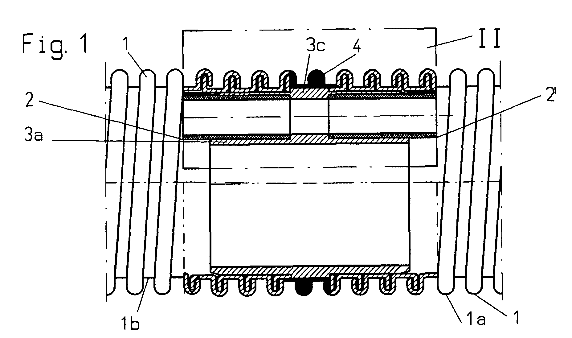
- 1 designates two identical hose sections, which are smooth on the inside and spiral crests 1a and troughs 1b on the outside exhibit.
- the tube sections 1 are made of thermoplastic by helically winding one Plastic existing profiled belt formed that a radial web and a Has hook part and an axial web connecting the radial web with the hook part.
- the hook part of a spiral passage overlaps the radial web of an adjacent spiral path and is connected to it (FIGS. 1 and 2).
- the type of winding has been known for a long time.
- the hose sections 1 each have a protective hose attached to their inner wall 2 for electrical conductors, not shown. Instead of taking electrical Conductors, the protective tube 2 can also be used to conduct a flowing medium, for example a cleaning liquid.
- the sleeve 3 with a sleeve is designated, which is shown enlarged in Fig. 3 in perspective.
- a through channel 3a is formed on the inside of the sleeve 3, into which the ends of the Engage protective hoses 2 of hose sections 1.
- the sleeve 3 is also with two to Attach the tube sections 1 to the formed shaft sections 3b (FIG. 3) and has a central annular collar 3c, which acts as a stop for the shaft sections 3b attached hose sections 1 is used.
- the through channel 3a is closed all around so that nothing can penetrate it from the outside (FIG. 3).
- Each end of the protective tube 2 engaging in the sleeve 3 is detached from the wall of the associated protective tube 1 in order to be able to push the apex 3d of the through-channel 3a freely into the respective tube section 1.
- the fastening 2a of the protective tube 2 on the inside of the assigned tube section 1 extends at most to the assigned end of the shaft portion 3b of the sleeve 3 and is then detached.
- the detachment of the fastening 2a of the protective tube 2 from the inside of the assigned tube section 1 is shown enlarged in FIG. 2.
- a plastic material 4 is applied all around to the collar 3c of the sleeve 3
- the outer contour is the same as the outer contour of the hose sections 1 and is smooth and smooth Contours of the hose sections 1 merges (Fig. 1 and 2).
- the plastic material 4 can be sprayed onto the collar 3c or applied by casting.
- the material 4 applied to the ring collar 3c is expediently the same or approximately equal to the material used for the hose sections 1 and has the same color like this.
- the width of the material applied to the collar 3c 4 at least over part of the circumference of the collar 3c equal to the width of a Wave crest 1a of the tube sections 1 plus approximately the width of two adjacent wave troughs 1b is the hose section 1.
Landscapes
- Engineering & Computer Science (AREA)
- General Engineering & Computer Science (AREA)
- Mechanical Engineering (AREA)
- Architecture (AREA)
- Civil Engineering (AREA)
- Structural Engineering (AREA)
- Rigid Pipes And Flexible Pipes (AREA)
- Quick-Acting Or Multi-Walled Pipe Joints (AREA)
- Branch Pipes, Bends, And The Like (AREA)
- Joints That Cut Off Fluids, And Hose Joints (AREA)
Abstract
Description
Aufgabe der Erfindung ist es, eine Muffe der im Oberbegriff des Anspruches 1 genannten Art zu schaffen, bei der die zu koppelnden Schlauchabschnitte nicht von einem Muffenbauteil überragt sind, und eine Dichtung zwischen den Schlauchabschnitten entbehrlich ist.
- Fig.1:
- einen Aufriß, teilweise im Schnitt.
- Fig. 2:
- eine Vergrößerung des in Fig. 1 strichpunktiert umrandeten Zeichnungsteils.
- Fig. 3:
- : eine perspektivische Darstellung einer Muffe.
Jedes Ende des in die Muffe 3 eingreifenden Schutzschlauches 2 ist von der Wand des zugeordneten Schutzschlauches 1 abgelöst, um den Scheitel 3d des Durchgangskanals 3a ungehindert in den jeweiligen Schlauchabschnitt 1 einschieben zu können. Mit anderen Worten, die Befestigung 2a des Schutzschlauches 2 an der Innenseite des zugeordneten Schlauchabschnittes 1 reicht maximal nur bis zum zugeordneten Ende des Schaftabschnittes 3b der Muffe 3 und ist dann abgelöst. Die Ablösung der Befestigung 2a des Schutzschlauches 2 von der Innenseite des zugeordneten Schlauchabschnittes 1 ist vergrößert in Fig. 2 dargestellt.
Claims (3)
- Muffe zum gleichachsigen Koppeln zweier gleich ausgebildeter Schlauchabschnitte, die innen glatt sind und außen wendelförmig verlaufende Wellenberge und Wellentäler aufweisen sowie einen an ihrer Innenseite befestigten, für die Aufnahme elektrischer Leiter dienenden Schutzschlauch tragen, dessen im Muffeninnern liegendes Ende von einem an der inneren Muffenwand angeformten Durchgangskanal umgriffen ist, während der Muffenmantel zwei zum Aufstecken der zugeordneten Schlauchabschnitte ausgebildete Schaftabschnitte und einen mittigen Ringbund als Anschlag für die Enden der Schlauchabschnitte aufweist, dadurch gekennzeichnet, daß der Durchgangskanal (3a) ein ringsum geschlossenes Rohr ist; daß jedes Schutzschlauchende für das ungehinderte Einschieben des Scheitels des Durchgangskanals (3a) in den zugeordneten Schlauchabschnitt (1) von der Innenseite des zugeordneten Schlauchabschnittes (1) abgelöst ist, und daß auf den Ringbund (3c) ringsum ein Kunststoffmaterial (4) aufgebracht ist, dessen Außenkontur gleich den Außenkonturen der benachbarten Schlauchabschnitte (1) ist und stoßfrei glatt in deren Außenkonturen übergeht.
- Muffe nach Anspruch 1, dadurch gekennzeichnet, daß das auf den Ringbund (3c) aufgebrachte Material (4) gleich dem Material der Schlauchabschnitte (1) ist und die gleiche Farbe wie die Schlauchabschnitte (1) aufweist.
- Muffe nach Anspruch 1 und 2, dadurch gekennzeichnet, daß die Breite des auf den Ringbund (3c) aufgebrachten Materials (4) mindestens über einen Teil des Umfanges des Ringbundes (3c) gleich der Breite eines Wellenberges (1a) der Schlauchabschnitte (1) plus etwa der Breite zweier angrenzender Wellentäler (1b) der Schlauchabschnitte (1) ist.
Applications Claiming Priority (2)
| Application Number | Priority Date | Filing Date | Title |
|---|---|---|---|
| DE20108878U DE20108878U1 (de) | 2001-05-29 | 2001-05-29 | Muffe zum gleichachsigen Koppeln zweier gleich ausgebildeter Schlauchabschnitte |
| DE20108878U | 2001-05-29 |
Publications (3)
| Publication Number | Publication Date |
|---|---|
| EP1262704A2 true EP1262704A2 (de) | 2002-12-04 |
| EP1262704A3 EP1262704A3 (de) | 2003-09-10 |
| EP1262704B1 EP1262704B1 (de) | 2005-04-13 |
Family
ID=7957395
Family Applications (1)
| Application Number | Title | Priority Date | Filing Date |
|---|---|---|---|
| EP02003394A Expired - Lifetime EP1262704B1 (de) | 2001-05-29 | 2002-02-14 | Muffe zum Koppeln von Mehrkanalrohren |
Country Status (4)
| Country | Link |
|---|---|
| EP (1) | EP1262704B1 (de) |
| AT (1) | ATE293228T1 (de) |
| DE (2) | DE20108878U1 (de) |
| ES (1) | ES2238513T3 (de) |
Cited By (1)
| Publication number | Priority date | Publication date | Assignee | Title |
|---|---|---|---|---|
| CN101842042B (zh) * | 2007-10-31 | 2012-09-26 | Bsh博世和西门子家用器具有限公司 | 家用器具 |
Families Citing this family (1)
| Publication number | Priority date | Publication date | Assignee | Title |
|---|---|---|---|---|
| DE102021003907A1 (de) | 2021-07-29 | 2023-02-02 | Truplast Kunststofftechnik Gesellschaft mit beschränkter Haftung | Flexibler schlauch, insbesondere staubsaugerschlauch, und verfahren zu dessen herstellung |
Family Cites Families (2)
| Publication number | Priority date | Publication date | Assignee | Title |
|---|---|---|---|---|
| DE29800808U1 (de) * | 1998-01-22 | 1998-03-12 | Truplast Kunststofftechnik GmbH, 35428 Langgöns | Saugschlauch für den Anschluß an ein Rohrleitungssystem einer zentralen Sauganlage |
| DE20001357U1 (de) * | 2000-01-26 | 2000-04-20 | Truplast Kunststofftechnik GmbH, 35428 Langgöns | Anschlussmuffe für einen mit einer Schutzhülle für zugentlastete elektrische Leiter versehenen Saugschlauch |
-
2001
- 2001-05-29 DE DE20108878U patent/DE20108878U1/de not_active Expired - Lifetime
-
2002
- 2002-02-14 EP EP02003394A patent/EP1262704B1/de not_active Expired - Lifetime
- 2002-02-14 ES ES02003394T patent/ES2238513T3/es not_active Expired - Lifetime
- 2002-02-14 AT AT02003394T patent/ATE293228T1/de not_active IP Right Cessation
- 2002-02-14 DE DE50202762T patent/DE50202762D1/de not_active Expired - Lifetime
Cited By (1)
| Publication number | Priority date | Publication date | Assignee | Title |
|---|---|---|---|---|
| CN101842042B (zh) * | 2007-10-31 | 2012-09-26 | Bsh博世和西门子家用器具有限公司 | 家用器具 |
Also Published As
| Publication number | Publication date |
|---|---|
| DE50202762D1 (de) | 2005-05-19 |
| ATE293228T1 (de) | 2005-04-15 |
| DE20108878U1 (de) | 2001-10-25 |
| EP1262704B1 (de) | 2005-04-13 |
| ES2238513T3 (es) | 2005-09-01 |
| EP1262704A3 (de) | 2003-09-10 |
Similar Documents
| Publication | Publication Date | Title |
|---|---|---|
| DE69203429T2 (de) | Verbesserungen an Rohrverbindungen von koaxialen Rohren. | |
| DE2358325C2 (de) | Vorrichtung für Rohrverbindungen | |
| DE2431516C3 (de) | Vorrichtung zur Abgabe von Fluiden | |
| DE2541242A1 (de) | Armatur fuer eine wellrohrleitung | |
| EP0214452B1 (de) | Insbesondere tragbare Trommel zur Aufnahme einer biegbaren Medium- bzw. Energieleitung wie Druckluftschlauch, Wasserschlauch, Elektrokabel od. dgl. | |
| DE3441040A1 (de) | Verbindungsschlauch | |
| DE3201049A1 (de) | Vorbereitungsaggregat zum vorbereiten eines fadenendes | |
| EP0836043A1 (de) | Verbindungselement zum Verbinden von Schlauch- und Rohrleitungsabschnitten | |
| DE845290C (de) | Armatur fuer Schlaeuche | |
| EP1262704B1 (de) | Muffe zum Koppeln von Mehrkanalrohren | |
| EP0877191B1 (de) | Anschlussmuffe für einen mit einer Schutzhülle für zugentlastete elektrische Leiter versehenen Schlauch | |
| DE19936413C1 (de) | Schlauchanschluß | |
| EP1265020B1 (de) | Flexible Gasleitung | |
| DE3536297A1 (de) | Schlauch und kupplung umfassende anordnung sowie schlauchkupplung hierfuer | |
| EP0607504B1 (de) | Hochdruckreinigungsgerät | |
| CH692429A5 (de) | Rohrverbindung. | |
| EP0709611B1 (de) | Einführungsvorrichtung für eine Gasleitung in ein Gebäude | |
| DE3911258C2 (de) | ||
| EP0884019B1 (de) | Staubsaugerschlauch mit elektrischen Leitern | |
| EP0744570A1 (de) | Absperrarmatur für eine unter Mediendruck stehende Rohrleitung | |
| CH712158B1 (de) | Schlauch, insbesondere Brauseschlauch. | |
| CH682944A5 (de) | Rohr zum zugfesten Verbinden mit weiteren Rohren. | |
| EP1036972B1 (de) | Anordnung zum Anschliessen einer Armatur | |
| DE69702288T2 (de) | Flexible Schlauchkonstruktion für Fluidkupplungen | |
| DE3941413C1 (en) | Joint for underground ventilation ducts - has hose fitted to inside of pipe at area of joint |
Legal Events
| Date | Code | Title | Description |
|---|---|---|---|
| PUAI | Public reference made under article 153(3) epc to a published international application that has entered the european phase |
Free format text: ORIGINAL CODE: 0009012 |
|
| AK | Designated contracting states |
Kind code of ref document: A2 Designated state(s): AT BE CH CY DE DK ES FI FR GB GR IE IT LI LU MC NL PT SE TR |
|
| AX | Request for extension of the european patent |
Free format text: AL;LT;LV;MK;RO;SI |
|
| PUAL | Search report despatched |
Free format text: ORIGINAL CODE: 0009013 |
|
| AK | Designated contracting states |
Kind code of ref document: A3 Designated state(s): AT BE CH CY DE DK ES FI FR GB GR IE IT LI LU MC NL PT SE TR |
|
| AX | Request for extension of the european patent |
Extension state: AL LT LV MK RO SI |
|
| RIC1 | Information provided on ipc code assigned before grant |
Ipc: 7H 02G 3/06 B Ipc: 7F 16L 39/02 B Ipc: 7F 16L 25/00 A Ipc: 7A 47L 9/24 B Ipc: 7F 16L 39/00 B |
|
| 17P | Request for examination filed |
Effective date: 20040220 |
|
| AKX | Designation fees paid |
Designated state(s): AT BE CH CY DE DK ES FI FR GB GR IE IT LI LU MC NL PT SE TR |
|
| GRAP | Despatch of communication of intention to grant a patent |
Free format text: ORIGINAL CODE: EPIDOSNIGR1 |
|
| GRAS | Grant fee paid |
Free format text: ORIGINAL CODE: EPIDOSNIGR3 |
|
| GRAA | (expected) grant |
Free format text: ORIGINAL CODE: 0009210 |
|
| AK | Designated contracting states |
Kind code of ref document: B1 Designated state(s): AT BE CH CY DE DK ES FI FR GB GR IE IT LI LU MC NL PT SE TR |
|
| PG25 | Lapsed in a contracting state [announced via postgrant information from national office to epo] |
Ref country code: FI Free format text: LAPSE BECAUSE OF FAILURE TO SUBMIT A TRANSLATION OF THE DESCRIPTION OR TO PAY THE FEE WITHIN THE PRESCRIBED TIME-LIMIT Effective date: 20050413 Ref country code: IE Free format text: LAPSE BECAUSE OF FAILURE TO SUBMIT A TRANSLATION OF THE DESCRIPTION OR TO PAY THE FEE WITHIN THE PRESCRIBED TIME-LIMIT Effective date: 20050413 |
|
| REG | Reference to a national code |
Ref country code: GB Ref legal event code: FG4D Free format text: NOT ENGLISH |
|
| REG | Reference to a national code |
Ref country code: CH Ref legal event code: EP |
|
| REG | Reference to a national code |
Ref country code: SE Ref legal event code: TRGR |
|
| REG | Reference to a national code |
Ref country code: IE Ref legal event code: FG4D Free format text: LANGUAGE OF EP DOCUMENT: GERMAN |
|
| REF | Corresponds to: |
Ref document number: 50202762 Country of ref document: DE Date of ref document: 20050519 Kind code of ref document: P |
|
| GBT | Gb: translation of ep patent filed (gb section 77(6)(a)/1977) |
Effective date: 20050608 |
|
| PG25 | Lapsed in a contracting state [announced via postgrant information from national office to epo] |
Ref country code: GR Free format text: LAPSE BECAUSE OF FAILURE TO SUBMIT A TRANSLATION OF THE DESCRIPTION OR TO PAY THE FEE WITHIN THE PRESCRIBED TIME-LIMIT Effective date: 20050713 Ref country code: DK Free format text: LAPSE BECAUSE OF FAILURE TO SUBMIT A TRANSLATION OF THE DESCRIPTION OR TO PAY THE FEE WITHIN THE PRESCRIBED TIME-LIMIT Effective date: 20050713 |
|
| REG | Reference to a national code |
Ref country code: ES Ref legal event code: FG2A Ref document number: 2238513 Country of ref document: ES Kind code of ref document: T3 |
|
| PG25 | Lapsed in a contracting state [announced via postgrant information from national office to epo] |
Ref country code: PT Free format text: LAPSE BECAUSE OF FAILURE TO SUBMIT A TRANSLATION OF THE DESCRIPTION OR TO PAY THE FEE WITHIN THE PRESCRIBED TIME-LIMIT Effective date: 20050913 |
|
| REG | Reference to a national code |
Ref country code: IE Ref legal event code: FD4D |
|
| PG25 | Lapsed in a contracting state [announced via postgrant information from national office to epo] |
Ref country code: AT Free format text: LAPSE BECAUSE OF NON-PAYMENT OF DUE FEES Effective date: 20060214 |
|
| PLBE | No opposition filed within time limit |
Free format text: ORIGINAL CODE: 0009261 |
|
| STAA | Information on the status of an ep patent application or granted ep patent |
Free format text: STATUS: NO OPPOSITION FILED WITHIN TIME LIMIT |
|
| PG25 | Lapsed in a contracting state [announced via postgrant information from national office to epo] |
Ref country code: BE Free format text: LAPSE BECAUSE OF NON-PAYMENT OF DUE FEES Effective date: 20060228 Ref country code: MC Free format text: LAPSE BECAUSE OF NON-PAYMENT OF DUE FEES Effective date: 20060228 Ref country code: LU Free format text: LAPSE BECAUSE OF NON-PAYMENT OF DUE FEES Effective date: 20060228 Ref country code: CH Free format text: LAPSE BECAUSE OF NON-PAYMENT OF DUE FEES Effective date: 20060228 Ref country code: LI Free format text: LAPSE BECAUSE OF NON-PAYMENT OF DUE FEES Effective date: 20060228 |
|
| ET | Fr: translation filed | ||
| 26N | No opposition filed |
Effective date: 20060116 |
|
| REG | Reference to a national code |
Ref country code: CH Ref legal event code: PL |
|
| BERE | Be: lapsed |
Owner name: TRUPLAST KUNSTSTOFFTECHNIK G.M.B.H. Effective date: 20060228 |
|
| PG25 | Lapsed in a contracting state [announced via postgrant information from national office to epo] |
Ref country code: TR Free format text: LAPSE BECAUSE OF FAILURE TO SUBMIT A TRANSLATION OF THE DESCRIPTION OR TO PAY THE FEE WITHIN THE PRESCRIBED TIME-LIMIT Effective date: 20050413 |
|
| PG25 | Lapsed in a contracting state [announced via postgrant information from national office to epo] |
Ref country code: CY Free format text: LAPSE BECAUSE OF FAILURE TO SUBMIT A TRANSLATION OF THE DESCRIPTION OR TO PAY THE FEE WITHIN THE PRESCRIBED TIME-LIMIT Effective date: 20050413 |
|
| PGFP | Annual fee paid to national office [announced via postgrant information from national office to epo] |
Ref country code: ES Payment date: 20081216 Year of fee payment: 8 |
|
| PGFP | Annual fee paid to national office [announced via postgrant information from national office to epo] |
Ref country code: NL Payment date: 20090224 Year of fee payment: 8 |
|
| PGFP | Annual fee paid to national office [announced via postgrant information from national office to epo] |
Ref country code: GB Payment date: 20090115 Year of fee payment: 8 |
|
| REG | Reference to a national code |
Ref country code: NL Ref legal event code: V1 Effective date: 20100901 |
|
| GBPC | Gb: european patent ceased through non-payment of renewal fee |
Effective date: 20100214 |
|
| PG25 | Lapsed in a contracting state [announced via postgrant information from national office to epo] |
Ref country code: NL Free format text: LAPSE BECAUSE OF NON-PAYMENT OF DUE FEES Effective date: 20100901 |
|
| REG | Reference to a national code |
Ref country code: ES Ref legal event code: FD2A Effective date: 20110308 |
|
| PG25 | Lapsed in a contracting state [announced via postgrant information from national office to epo] |
Ref country code: GB Free format text: LAPSE BECAUSE OF NON-PAYMENT OF DUE FEES Effective date: 20100214 |
|
| PG25 | Lapsed in a contracting state [announced via postgrant information from national office to epo] |
Ref country code: ES Free format text: LAPSE BECAUSE OF NON-PAYMENT OF DUE FEES Effective date: 20110307 |
|
| PG25 | Lapsed in a contracting state [announced via postgrant information from national office to epo] |
Ref country code: ES Free format text: LAPSE BECAUSE OF NON-PAYMENT OF DUE FEES Effective date: 20100215 |
|
| PGFP | Annual fee paid to national office [announced via postgrant information from national office to epo] |
Ref country code: SE Payment date: 20140217 Year of fee payment: 13 |
|
| REG | Reference to a national code |
Ref country code: SE Ref legal event code: EUG |
|
| PG25 | Lapsed in a contracting state [announced via postgrant information from national office to epo] |
Ref country code: SE Free format text: LAPSE BECAUSE OF NON-PAYMENT OF DUE FEES Effective date: 20150215 |
|
| REG | Reference to a national code |
Ref country code: FR Ref legal event code: PLFP Year of fee payment: 15 |
|
| REG | Reference to a national code |
Ref country code: FR Ref legal event code: PLFP Year of fee payment: 16 |
|
| REG | Reference to a national code |
Ref country code: FR Ref legal event code: PLFP Year of fee payment: 17 |
|
| PGFP | Annual fee paid to national office [announced via postgrant information from national office to epo] |
Ref country code: FR Payment date: 20210205 Year of fee payment: 20 |
|
| PGFP | Annual fee paid to national office [announced via postgrant information from national office to epo] |
Ref country code: DE Payment date: 20210222 Year of fee payment: 20 |
|
| PGFP | Annual fee paid to national office [announced via postgrant information from national office to epo] |
Ref country code: IT Payment date: 20210212 Year of fee payment: 20 |
|
| REG | Reference to a national code |
Ref country code: DE Ref legal event code: R071 Ref document number: 50202762 Country of ref document: DE |