EP1262770A2 - Photoionisationsdetektor und Verfahren für kontinuierlichen Betrieb und gleichzeitige Selbstreinigung - Google Patents
Photoionisationsdetektor und Verfahren für kontinuierlichen Betrieb und gleichzeitige Selbstreinigung Download PDFInfo
- Publication number
- EP1262770A2 EP1262770A2 EP02253724A EP02253724A EP1262770A2 EP 1262770 A2 EP1262770 A2 EP 1262770A2 EP 02253724 A EP02253724 A EP 02253724A EP 02253724 A EP02253724 A EP 02253724A EP 1262770 A2 EP1262770 A2 EP 1262770A2
- Authority
- EP
- European Patent Office
- Prior art keywords
- gas
- ionization chamber
- gas detection
- pid
- ambient
- Prior art date
- Legal status (The legal status is an assumption and is not a legal conclusion. Google has not performed a legal analysis and makes no representation as to the accuracy of the status listed.)
- Granted
Links
Images



Classifications
-
- G—PHYSICS
- G01—MEASURING; TESTING
- G01N—INVESTIGATING OR ANALYSING MATERIALS BY DETERMINING THEIR CHEMICAL OR PHYSICAL PROPERTIES
- G01N33/00—Investigating or analysing materials by specific methods not covered by groups G01N1/00 - G01N31/00
- G01N33/0004—Gaseous mixtures, e.g. polluted air
- G01N33/0009—General constructional details of gas analysers, e.g. portable test equipment
- G01N33/0026—General constructional details of gas analysers, e.g. portable test equipment using an alternating circulation of another gas
-
- G—PHYSICS
- G01—MEASURING; TESTING
- G01N—INVESTIGATING OR ANALYSING MATERIALS BY DETERMINING THEIR CHEMICAL OR PHYSICAL PROPERTIES
- G01N27/00—Investigating or analysing materials by the use of electric, electrochemical, or magnetic means
- G01N27/62—Investigating or analysing materials by the use of electric, electrochemical, or magnetic means by investigating the ionisation of gases, e.g. aerosols; by investigating electric discharges, e.g. emission of cathode
- G01N27/64—Investigating or analysing materials by the use of electric, electrochemical, or magnetic means by investigating the ionisation of gases, e.g. aerosols; by investigating electric discharges, e.g. emission of cathode using wave or particle radiation to ionise a gas, e.g. in an ionisation chamber
- G01N27/66—Investigating or analysing materials by the use of electric, electrochemical, or magnetic means by investigating the ionisation of gases, e.g. aerosols; by investigating electric discharges, e.g. emission of cathode using wave or particle radiation to ionise a gas, e.g. in an ionisation chamber and measuring current or voltage
-
- G—PHYSICS
- G01—MEASURING; TESTING
- G01N—INVESTIGATING OR ANALYSING MATERIALS BY DETERMINING THEIR CHEMICAL OR PHYSICAL PROPERTIES
- G01N33/00—Investigating or analysing materials by specific methods not covered by groups G01N1/00 - G01N31/00
- G01N33/0004—Gaseous mixtures, e.g. polluted air
- G01N33/0009—General constructional details of gas analysers, e.g. portable test equipment
- G01N33/0027—General constructional details of gas analysers, e.g. portable test equipment concerning the detector
- G01N33/0029—Cleaning of the detector
-
- H—ELECTRICITY
- H01—ELECTRIC ELEMENTS
- H01J—ELECTRIC DISCHARGE TUBES OR DISCHARGE LAMPS
- H01J41/00—Discharge tubes for measuring pressure of introduced gas or for detecting presence of gas; Discharge tubes for evacuation by diffusion of ions
- H01J41/02—Discharge tubes for measuring pressure of introduced gas or for detecting presence of gas
-
- G—PHYSICS
- G01—MEASURING; TESTING
- G01N—INVESTIGATING OR ANALYSING MATERIALS BY DETERMINING THEIR CHEMICAL OR PHYSICAL PROPERTIES
- G01N33/00—Investigating or analysing materials by specific methods not covered by groups G01N1/00 - G01N31/00
- G01N33/0004—Gaseous mixtures, e.g. polluted air
- G01N33/0009—General constructional details of gas analysers, e.g. portable test equipment
- G01N33/0027—General constructional details of gas analysers, e.g. portable test equipment concerning the detector
- G01N33/0036—General constructional details of gas analysers, e.g. portable test equipment concerning the detector specially adapted to detect a particular component
- G01N33/0047—Organic compounds
Definitions
- This invention relates to a volatile gas detector, particularly to a continuously operated photo-ionization detector (PID), and a method for real-time self-cleaning of the volatile gas detector.
- PID photo-ionization detector
- Photo-ionization detectors can detect volatile gases.
- Fig. 1 shows a conventional portable PID 10 that includes an ultraviolet (UV) lamp 12 and an ionization chamber 14.
- UV lamp 12 produces UV light including UV photons having energy up to 8.4 electron volts (eV) or more.
- the UV photons pass through an optical window 16 into ionization chamber 14.
- the UV photons collide with and ionize volatile gas molecules having ionization potentials below the energy of the photons, creating ions and electrons.
- PID 10 further includes an ion detector 18 having a pair of electrodes 20 and 22, which are typically made of a metal.
- Ion detector 18 has a high voltage (150 V or more) applied across electrodes 20 and 22 to generate an electrical field.
- electrode 22 is biased to a high voltage to attract negatively charged particles (electrons) and repel positively charged particles (ions), and electrode 20 is grounded to collect the positively charged particles (ions). The movement of the ions to electrode 22 produces a current, from which the concentration of the volatile gas can be determined.
- contamination such as a coating of metal atoms, oil film, dust particles, and/or other polymer-like coating, often builds up inside ionization chamber 14, especially on electrodes 20 and 22 and window 16.
- the contamination on electrodes 20 and 22 reduces the accuracy of volatile gas concentration measurement by preventing the ion and electron collection of electrodes 20 and 22.
- the contamination on window 16 decreases the intensity of the UV light introduced to ionization chamber 14 from UV lamp 12, and thus reduces the accuracy of volatile gas concentration measurement. Accordingly, PID 10 must be regularly dissembled and cleaned to remove such contamination.
- a traditional PID usually loses sensitivity to gas by 10% to 20% per day because of contamination during continuous operation.
- the UV light from the UV lamp converts oxygen in the gas sample to ozone, which is a strong oxidant.
- the ozone etches and removes the contamination inside the ionization chamber, that is, the contamination on electrodes and window. After the contamination has been etched and removed, the products of the contamination removal are discharged from the ionization chamber. After self-cleaning for a period of time, the PID can almost fully recover the sensitivity that was lost due to contamination. But this technique does not offer a continuous operation which is required in most fixed systems for processing control and safety protection.
- the PID of U.S. Patent No. 6,225,633 has several shortcomings. First, when the gas sample includes little or no oxygen, the effectiveness of the self-cleaning will be decreased. Second, while the PID is being self-cleaned, the PID cannot measure the concentration of volatile gas molecules existing in the ambient area. In other words, the PID cannot perform real-time measurement of the concentration of volatile gas molecules.
- the effectiveness of PIDs diminishes due to the build-up of contamination, such as a coating of metal atoms, oil film, dust particles, or other polymer-like coating substances, in an ionization chamber of the PID.
- contamination such as a coating of metal atoms, oil film, dust particles, or other polymer-like coating substances
- the contamination on an optical window of the PID can gradually decrease the UV intensity from a UV lamp to the ionization chamber, resulting in inaccurate measurement of volatile gas concentration. Accordingly, a user must dissemble the PID to clean ionization chamber. Further, while the PID is being cleaned, the volatile gas concentration cannot be measured.
- the present invention provides PIDs capable of self-cleaning and real-time measurement of the concentration of volatile gas molecules existing in the environment.
- the invention also provides methods that enable the PIDs to continuously perform self-cleaning and real-time measurement of the concentration of volatile gas molecules.
- a photo-ionization detector includes a microprocessor and a gas detection unit that measures a current corresponding to a concentration of a volatile gas in an ambient gas.
- the gas detection unit includes an ionization chamber, a UV lamp that ionizes the ambient gas in the ionization chamber, a bias electrode, and a measurement electrode.
- the microprocessor controls the gas detection unit such that the flow of the ambient gas in the ionization chamber is intermittently interrupted, and the UV lamp converts oxygen in the closed ambient gas to ozone.
- the PID further includes a container that contains an oxygen-containing gas, which is supplied into the ionization chamber when the flow of the ambient gas is interrupted in the ionization chamber, so that the oxygen-containing gas is converted to ozone.
- the PID further includes a lamp driver, a bias driver circuit, and a measurement driver circuit. The microprocessor controls the lamp driver circuit, the bias driver circuit, and the measurement driver circuit.
- the PID further includes a pump and a pump driver circuit, through which the microprocessor controls the pump.
- the pump is between the microprocessor and the gas detection unit, wherein the microprocessor intermittently closes the flow of the ambient gas in the ionization chamber by turning on and off the pump.
- a PID includes a microprocessor and multiple gas detection units.
- Each of the gas detection units measures a current corresponding to a concentration of a volatile gas in an ambient gas and includes an ionization chamber, a UV lamp, a bias electrode, and a measurement electrode.
- the microprocessor controls the gas detection units such that the flow of the ambient gas is prevented in the ionization chamber of at least one of the gas detection units while the ambient gas flow through the ionization chamber of at least another one of the gas detection units is permitted.
- the UV lamp converts oxygen in the closed ambient gas to ozone, which removes contamination in the ionization chamber with the closed ambient gas.
- the PID further includes a container that contains an oxygen-containing gas, which is supplied into the ionization chamber, in which the flow of the ambient gas is prevented.
- the PID further includes a multi-port valve, a pump, and a pump driver circuit, through which the microprocessor controls the pump.
- the pump is between the microprocessor and the gas detection units, the pump moving the ambient gas through the ionization chambers of the gas detection units.
- the multi-port valve is coupled to the ionization chamber of each of the gas detection units and the pump, and opens and closes the ionization chamber of each of the plurality of the gas detection units to the flow of the ambient gas, while the pump is turned on.
- a PID includes a microprocessor, a first gas detection unit, and a second gas detection unit.
- the microprocessor controls the first and second gas detection units such that the ambient gas always flows through the ionization chamber of one of the gas detection units and the flow of the ambient gas is prevented in the ionization chamber of the other one of the gas detection units.
- the UV lamp converts oxygen in the closed ambient gas to ozone, which removes contamination in the ionization chamber with the closed ambient gas.
- the PID further includes a container that contains an oxygen-containing gas, which is supplied into the ionization chamber, in which the flow of the ambient gas is prevented.
- the PID further includes a three-way valve, a pump, and a pump driver circuit, through which the microprocessor controls the pump.
- the pump is between the microprocessor and the gas detection units, the pump providing the ambient gas through the ionization chambers of the gas detection units.
- the three-way valve connected to the ionization chamber of each of the gas detection units and the pump permits ambient gas flow in the ionization chamber of one or the other of the gas detection units while the pump is turned on.
- the flow of ambient gas is permitted in the ionization chamber of one of the first and second gas detection units from which contamination has been removed during a time when ambient gas is prevented from flowing in the ionization chamber of the other of the first and second gas detection units to permit cleaning the ionization chamber of the other detection unit.
- Another aspect of the present invention provides a method of real-time self-cleaning and measuring of a volatile gas concentration with a PID that comprises a gas detection unit including an ionization chamber, in which an ambient gas including a volatile gas is ionized by a UV lamp.
- the method includes causing the ambient gas to flow through the ionization chamber, to permit the PID to measure the volatile gas concentration, and causing the flow of the ambient gas through the ionization chamber and periodically interrupting the flow.
- the flow is on for a first period of time and off for a second period of time, and during the second period of time the UV lamp converts oxygen contained in the ambient gas to ozone to remove contamination in the ionization chamber.
- the method further includes supplying an oxygen-containing gas into the ionization chamber.
- the switch between flowing the ambient gas and stopping the flow of the ambient gas occurs by turning on and off a pump connected to the ionization chamber.
- Still another aspect of the present invention provides a method of real-time self-cleaning and measuring of a volatile gas concentration with a PID that includes multiple gas detection units, each of the gas detection units including an ionization chamber, in which an ambient gas including a volatile gas is ionized by a UV lamp.
- the method includes flowing the ambient gas through the ionization chamber of one of the gas detection units, so that the PID measures the volatile gas concentration and stopping the flow of the ambient gas in the ionization chamber of another of the gas detection units so that the UV lamp converts oxygen contained in the ambient gas in the ionization chamber of the another gas detection unit to ozone, which removes contamination in the ionization chamber with the closed ambient gas.
- the method further includes supplying an oxygen-containing gas into the ionization chamber in which the flow ambient gas is stopped.
- Each of the gas detection units is repeatedly switched between flowing and stopping the ambient gas.
- the switch between flowing and stopping the ambient gas is achieved by using a multi-port valve connected between a pump and the ionization chamber of each of the gas detection units.
- Still another aspect of the present invention provides a method of real-time self-cleaning and measuring of a volatile gas concentration with a photo-ionization detector (PID) that includes a first gas detection unit and a second gas detection unit, each of the gas detection units including an ionization chamber, in which an ambient gas including a volatile gas is ionized by a UV lamp.
- the method includes flowing the ambient gas through the ionization chamber of the first gas detection unit, so that the PID measures the volatile gas concentration, and stopping the ambient gas through the ionization chamber of the second gas detection unit so that the ambient gas is closed in the ionization chamber of the second gas detection unit while the ambient gas flows through the ionization chamber of the first gas detection unit.
- the UV lamp converts oxygen contained in the ambient gas in the ionization chamber of the second gas detection unit to ozone, which removes contamination in the ionization chamber of the second gas detection unit.
- the method further includes supplying an oxygen-containing gas into the ionization chamber in which the flow of ambient gas is stopped.
- Flowing and stopping the flow of ambient gas are repeatedly switched between the first and second gas detection-units.
- The-switch between flowing and stopping the flow of ambient gas is achieved by using a three valve connected between a pump and the ionization chamber of each of the gas detection units.
- Fig. 1 is a block diagram of a conventional photo-ionization detector.
- Fig. 2 is a block diagram of a photo-ionization detector in accordance with an embodiment of the present invention.
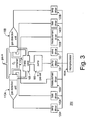
- Fig. 3 is a block diagram of a photo-ionization detector in accordance with another embodiment of the present invention.
- Fig. 4 is a cross-sectional view illustrating a volatile gas detection unit for the photo-ionization detectors of Figs. 2 and 3.
- the present invention is directed to photo-ionization detectors capable of self-cleaning and real-time measurement of the concentration of volatile gas molecules existing in the environment.
- the invention also provides methods that enable the photo-ionization detectors to continuously perform self-cleaning and real-time measurement of the concentration of volatile gas molecules.
- Fig. 2 shows a photo-ionization detector (PID) 100 in accordance with an embodiment of the present invention
- Fig. 4 shows a volatile gas detection unit 110 for the PIDs 100 and 200 of Figs 2 and 3.
- PID 100 is a miniaturized and continuously opereated detector of volatile gases.
- PID 100 includes a volatile gas detection unit 110, an ultra-violet (UV) lamp driver circuit 120, a pump driver circuit 130, a bias driver circuit 140, a measurement driver circuit 150, a pump 160, an oxygen-containing gas container 170, and a microprocessor 180.
- UV ultra-violet
- gas detection unit 110 includes a UV lamp 32, which is sealed by an envelope 38, an optical window 34, and an ionization chamber 36.
- UV lamp 32 radiates UV photons or UV light 60 (light having a wavelength less than about 150 nm) through optical window 34 into ionization chamber 36.
- Envelope 38 which is preferably made of glass, contains a UV light source (not shown) and a mixture of inert gases such as helium (e.g., 40%), argon (e.g., 30%) and krypton (e.g., 30%), at a reduced pressure (e.g., 25 Torr).
- Exemplary dimensions for envelope 38 are 0.10-1.00 inch in diameter and 0.20-2.00 inch in length.
- Optical window 34 is disposed at the end of envelope 38 and is made of a single crystal material. Depending on the material of choice for optical window 34, UV light having a desired energy level pass through optical window 34.
- optical window 34 made of lithium fluoride (LiF), magnesium fluoride (MgF 2 ), barium fluoride (BaF 2 ), or calcium fluoride (CaF 2 ) allows the transmission of the UV light of 11.7 electron volts (eV), 10.6 eV, 9.8 eV, or 9.2 eV, respectively.
- Gas detection unit 110 may be constructed as disclosed in a U.S. Patent Application Serial No.
- Lamp driver circuit 120 is connected to gas detection unit 110 to drive UV lamp 32.
- Microprocessor 180 can adjust the UV light intensity of UV lamp 32 by controlling lamp driver circuit 120. Details of the function and structure of lamp driver circuit 120 are described in the above-incorporated U.S. Patent No. 6,225,633 and commonly owned U.S. Patent No. 5,773,833 to Hsi, entitled “Photo-ionization Detector For Volatile Gas Measurement” and issued on June 30, 1998, which is incorporated herein by reference in its entirety.
- the UV photons 60 from UV lamp 32 ionize volatile gas molecules inside ionization chamber 36.
- Each of ion detectors 46 and 48 includes a pair of electrodes, a bias electrode 50 or 54 and a measurement electrode 52 or 56.
- Bias electrodes 50 and 54 and measurement electrodes 52 and 56 are positioned in an interdigital arrangement.
- Each of bias and measurement electrodes 50, 54, 52, and 56 has at least a pair of digits, positioned in the interdigital arrangement.
- bias and measurement electrodes 50, 54, 52, and 56 can each have from one to a number of digits.
- the above-incorporated U.S. Patent Application Serial No. 09/271,612 describes in detail the interdigital arrangement, structures and fabrication methods of bias and measurement electrodes 50, 54, 52, and 56.
- bias and measurement electrodes 50, 54, 52, and 56 can have straight or "step-like" shape and be formed by machine manufacturing various metals and alloys, preferably stainless steel.
- Bias and measurement electrodes 50, 54, 52, and 56 can also be formed by depositing a conductive electrode layer on a substrate, masking selected portions of the electrode layer, and etching and removing the remaining portions from the substrate to produce the interdigital electrode pattern. Subsequent to the etching process, the substrate is removed from the produced interdigital electrode.
- a transparent substrate may be used that allows UV light to be transmitted therethrough, thus avoiding the removal of the substrate.
- portions of the substrate can be removed to form a pattern that matches the interdigital electrode in shape. Examples of material used for the electrode layer and substrate include platinum on a ceramic substrate, copper on a printed circuit board, and gold on a silicon wafer.
- bias and measurement electrodes 50, 54, 52, and 56 are about 0.01 to 0.20 inches in thickness T, most preferably about 0.02 inches, and about 0.01 to 0.08 inches in width W, most preferably about 0.02 inches.
- the distance or separation D between bias and measurement electrodes 50, 54, 52, and 56 is about 0.01 to 0.20 inches, most preferably about 0.03 inches. It is understood that these dimensions are illustrative in nature and that bias and measurement electrodes 50, 54, 52, and 56 can have other thickness, width, and separation.
- gas detection unit 110 includes a UV shield 62 between optical window 34 and ion detectors 46 and 48 that shields measurement electrode 56 of ion detector 48 from UV light 60.
- UV light 60 striking ion detectors 46 and 48 can liberate electrons from electrodes 50, 52 and 54. Electrons liberated from bias electrodes 50 and 54 are, in general, attracted back to positive bias electrodes 50 and 54 and do not contribute to a base line current (i.e., a current presented even in the absence of ionizable gases) in respective ion detectors 46 and 48. However, bias electrodes 50 and 54 can capture electrons liberated from measurement electrodes 52 and 56 which leads to a base line current.
- UV shield 62 which is preferably made of a polytetrafluoroethene (Teflon) sheet, is between optical window 34 and measurement electrode 56 and stops UV light 60 from striking measurement electrode 56. Even though, as shown in Fig. 2, this embodiment completely shields measurement electrode 56 from UV light 60 and completely exposes measurement electrode 52, another embodiment allows UV light 60 to strike electrodes 52 and 56 at different degrees. In other words, UV shield 62 differentially exposes electrodes 52 and 56 to UV light 60.
- a layer of material (not shown) which is inert to the gases and ions generated in ionization chamber 36, has an electrical insulation property, and is opaque to high energy UV light may be employed as a UV shield on electrode 56.
- a photo-resist polymer made of polytetrafluoroethene (Teflon) or a ceramic layer made of alumina may be formed on a surface of measurement electrode 56 facing optical window 34 to serve as a UV shield.
- the UV shield as just described may also be employed for bias electrodes 50 and 54.
- measurement electrodes 52 and 56 are,near ground voltage and separated from bias electrodes 50 and 54 to create an electrical field 58.
- bias driver circuit 140 provides a positive bias voltage (e.g., DC voltage of about 4-120V) to bias electrodes 50 and 54.
- Measurement driver circuit 150 is connected to measurement electrodes 52 and 56 and measures the electrical currents caused by the collection of the ions, i.e., the measurement currents.
- the above-incorporated 5,773,833 patent discloses embodiments of measurement driver circuit 150.
- Microprocessor 180 communicates with both bias driver circuit 140 and measurement driver circuit 150 and can adjust the bias voltage that bias driver circuit 140 applies to bias electrodes 50 and 54.
- Measurement driver circuit 150 sends signals indicative of the measurement currents measured at detectors 46 and 48 to microprocessor 180 in order to determine the concentration of the volatile gas molecules. Based on pre-calibration data, microprocessor 180 converts the current signal into an equivalent concentration of gases. Details of the determination of the volatile gas concentration is disclosed in the above-incorporated U.S. Patent Application Serial No. 09/271,612 .
- the UV intensity in gas detection unit 110 can vary for a variety of reasons, including degradation of the electrical performance of UV lamp 32, contamination of optical window 34 by polymer-like substances, and presence of interfering substances (i.e., substances which can absorb or enhance UV photons, e.g., methane, water, carbon monoxide, nitrogen, etc.).
- interfering substances i.e., substances which can absorb or enhance UV photons, e.g., methane, water, carbon monoxide, nitrogen, etc.
- PID 100 includes pump 160 and pump driver circuit 130 to control the flow of gases into and out of ionization chamber 36 of gas detection unit 110.
- Pump 160 is connected to pump driver circuit 130, which in turn is connected to microprocessor 180 for controlling pump 160.
- Ionization chamber 36 is an open volume chamber, receiving a laminar flow of gases.
- Pump 160 provides a flow of gases (e.g., 200-600 ml/min) into and out of ionization chamber 36. When pump 160 is turned off, gases are prevented from flowing into or out of ionization chamber 36.
- the laminar flow of gases through ionization chamber 36 is parallel to a plane defined by the surface of optical window 34. Furthermore, the flow of gases is perpendicular to electrical field 58 of bias and measurement electrodes 50, 54, 52, and 56. Thus, gases flow easily between bias and measurement electrodes 50, 54, 52, and 56, and more ions are collected by measurement electrodes 52 and 56.
- the flow of gases is also perpendicular to the direction of propagation of UV light 60. Accordingly, the perpendicular relationship between UV light 60 and the gas flow facilitates ionization of a greater percentage of gas molecules between electrodes 50 and 52 and 54 and 56, and also allows for a greater collection of the ion molecules by measurement electrodes 52 and 56.
- the contamination includes a coating of metal atoms, oil film, dust particles, and other polymer-like coating substances. Accordingly, the contamination must be removed regularly.
- PID 100 includes oxygen-containing gas container 170 and an oxygen pump 175 for real-time self-cleaning of ionization chamber 36.
- microprocessor 180 turns pump 160 on and off while maintaining transmission of UV lamp 32 for self-cleaning.
- microprocessor 180 turns pump 160 on, ambient gases flow through ionization chamber 36, so that the volatile gas concentration in the ambient gases is measured.
- microprocessor 180 turns off the oxygen pump such that an oxygen-containing gas in container 170 is not introduced into ionization chamber 36.
- microprocessor 180 turns off pump 160 intermittently.
- pump 160 When pump 160 is turned off, the ambient gases are prevented from entering into and exiting out of ionization chamber 36, and microprocessor 180 turns on the oxygen pump to supply the oxygen-containing gas into ionization chamber 36.
- UV light 60 converts oxygen, enclosed in ionization chamber 36, to ozone.
- Ozone a strong oxidant, accumulates in ionization chamber 36 and oxidizes, i.e., etches and removes, contamination from ionization chamber 36, including surfaces of bias and measurement electrodes 50, 54, 52, and 56 and optical window 34.
- pump 160 is turned on again to flush and discharge the contamination out of ionization chamber 36 and to introduce the ambient gases into ionization chamber 36 to continue to measure the volatile gas concentration of the ambient gases.
- microprocessor 180 repeatedly turns pump 160 and oxygen pump 190 on and off.
- PID 100 can measure the volatile gas concentration every second and continuously clean ionization chamber 36.
- self-cleaning may require several minutes.
- the ambient gas includes such an amount of oxygen that it can produce enough ozone to remove the contamination in ionization chamber 36, the introduction of the oxygen-containing gas into ionization chamber 36 is not necessary.
- microprocessor 180 may also execute firmware.
- the firmware provides a user interface for controlling PID 100, displaying the volatile gas concentration, and generating warning signals if the volatile gas concentration reaches designated threshold levels. Controls, an alarm, and a liquid crystal display (not shown) provide a hardware portion of the user interface.
- a non-volatile memory such as a ROM, EEROM, or Flash Memory (not shown) contains the firmware and parameters for calibration of PID 100.
- a volatile memory may also be required unless microprocessor 180 contains sufficient on-chip memory for execution of the firmware.
- Fig. 3 illustrates a PID 200 in accordance with another embodiment of the present invention.
- PID 200 includes two gas detection units 110A and 110B, two lamp driver circuits 120A and 120B, a pump driver circuit 130, two bias driver circuits 140A and 140B, two measurement driver circuits 150A and 150B, a valve driver circuit 135, a pump 160, a three-way valve 165, and a microprocessor 180A.
- Gas detection units 110A and 110B, lamp driver circuits 120A and 120B, pump driver circuit 130, bias driver circuits 140A and 140B, and measurement driver circuits 150A and 150B, pump 160 may be implemented identically to gas detection unit 110, lamp driver circuit 120, pump driver circuit 130, bias driver circuit 140, measurement driver circuit 150, and pump 160 of Fig. 2, respectively.
- Microprocessor 180A of PID 200 is of course programmed differently from microprocessor 180 of PID 100 since microprocessor 180A provides additional controls as described below.
- Lamp driver circuit 120A, bias driver circuit 140A, and measurement driver circuit 150A are for operating gas detection unit 110A
- lamp driver circuit 120B, bias driver circuit 140B, and measurement driver circuit 150B are for operating gas detection unit 110B.
- microprocessor 180A of PID 200 operates gas detection units 110A and 110B by controlling lamp driver circuits 120A and 120B, pump driver circuit 130, bias driver circuits 140A and 140B, and measurement driver circuits 150A and 150B.
- Three-way valve 165 is connected to each of gas detection units 110A and 110B and pump 160, and valve driver circuit 135 is connected between microprocessor 180 and three-way valve 165.
- Microprocessor 180A controls valve driver circuit 135 such that, when pump 160 is on, a flow of ambient gas occurs either through the ionization chamber of gas detection unit 110A or through the ionization chamber of gas detection unit 110B.
- pump 160 is always on during the operation of PID 200, while pump 160 is intermittently on and off during the operation of PID 100.
- one of gas detection units 110A and 110B is employed to measure the volatile gas concentration, while the other is in a self-cleaning cycle. After the self-cleaning cycle is finished, the self-cleaned gas detection unit 110A or 110B measures the volatile gas concentration, and the other one 110A or 110B is self-cleaned.
- PID 200 always turns on the UV lamps of gas detection units 110A and 110B.
- the interchange between gas detection units 110A and 110B for self-cleaning and measurement is accomplished by three-way valve 165.
- Microprocessor 180A intermittently switches the opening of inlets (not shown) of three-way valve 165, which are connected to the outlets of the ionization chambers of gas detection units 110A and 110B, respectively.
- the inlet of three-way valve 165 connected to gas detection unit 110A is opened, the inlet of three-way valve 165 connected to the outlet of gas detection unit 110B is closed.
- pump 160 produces a flow of ambient gas through the ionization chamber of gas detection unit 110A, so that gas detection unit 110A sends a current signal corresponding to the volatile gas concentration of the ambient gas to microprocessor 180A.
- gas detection unit 110A is measuring the volatile gas concentration
- gas detection unit 110B self-cleans by converting the oxygen contained in the ambient gas closed in the ionization chamber of gas detection unit 110B as described with respect of PID 100 of Fig. 2.
- microprocessor 180A switches the opening of the inlets of three-way valve 165, such that the inlet of three-way valve 165 to gas detection unit 110A is closed and the inlet of three-way valve 165 connected to gas detection unit 110B is opened. Then, gas detection unit 110A self-cleans, and gas detection unit 110B measures the volatile gas concentration. PID 200 repeats such a switching procedure of measuring and self-cleaning to keep both gas detection units 110A and 110B clean and measure the volatile gas concentration without interruption.
- PID 200 employs only two gas detection units
- another PID according to the present invention may integrate three or more gas detection units for real-time self cleaning and uninterrupted measuring of the volatile gas concentration.
- a multi-port valve is used instead of three-way valve 165 of Fig. 3.
- an oxygen-containing gas can be provided into PID 200 in a similar way that was described with respect to PID 100.
- An oxygen-containing gas container 170A and an oxygen pump (not shown) of PID 200 are connected to the ionization chambers of gas detection units 110A and 110B, so that the oxygen-containing gas is supplied into the ionization chamber of gas detection unit 110A or 110B, in which the flow of the ambient gas was stopped.
Landscapes
- Chemical & Material Sciences (AREA)
- Health & Medical Sciences (AREA)
- Life Sciences & Earth Sciences (AREA)
- Engineering & Computer Science (AREA)
- Analytical Chemistry (AREA)
- General Physics & Mathematics (AREA)
- Pathology (AREA)
- Physics & Mathematics (AREA)
- Immunology (AREA)
- Biochemistry (AREA)
- General Health & Medical Sciences (AREA)
- Combustion & Propulsion (AREA)
- Food Science & Technology (AREA)
- Medicinal Chemistry (AREA)
- Toxicology (AREA)
- Chemical Kinetics & Catalysis (AREA)
- Electrochemistry (AREA)
- Other Investigation Or Analysis Of Materials By Electrical Means (AREA)
Applications Claiming Priority (2)
| Application Number | Priority Date | Filing Date | Title |
|---|---|---|---|
| US870179 | 2001-05-29 | ||
| US09/870,179 US6734435B2 (en) | 2001-05-29 | 2001-05-29 | Photo-ionization detector and method for continuous operation and real-time self-cleaning |
Publications (3)
| Publication Number | Publication Date |
|---|---|
| EP1262770A2 true EP1262770A2 (de) | 2002-12-04 |
| EP1262770A3 EP1262770A3 (de) | 2003-04-16 |
| EP1262770B1 EP1262770B1 (de) | 2012-06-20 |
Family
ID=25354914
Family Applications (1)
| Application Number | Title | Priority Date | Filing Date |
|---|---|---|---|
| EP02253724A Expired - Lifetime EP1262770B1 (de) | 2001-05-29 | 2002-05-28 | Photoionisationsdetektor und Verfahren für kontinuierlichen Betrieb und gleichzeitige Selbstreinigung |
Country Status (3)
| Country | Link |
|---|---|
| US (1) | US6734435B2 (de) |
| EP (1) | EP1262770B1 (de) |
| JP (1) | JP4053817B2 (de) |
Cited By (18)
| Publication number | Priority date | Publication date | Assignee | Title |
|---|---|---|---|---|
| RU2293311C1 (ru) * | 2005-09-28 | 2007-02-10 | ООО Бюро аналитического приборостроения ХРОМДЕТ-ЭКОЛОГИЯ | Газоанализатор |
| RU2315287C2 (ru) * | 2004-12-09 | 2008-01-20 | ООО Бюро аналитического приборостроения ХРОМДЕТ-ЭКОЛОГИЯ | Способ анализа примесей веществ в газе и устройство для его осуществления |
| RU2350941C1 (ru) * | 2007-06-26 | 2009-03-27 | ООО Бюро аналитического приборостроения ХРОМДЕТ-ЭКОЛОГИЯ | Газоанализатор и способ его работы |
| CN100567975C (zh) * | 2003-03-07 | 2009-12-09 | 气体感觉分析有限责任公司 | 用于检测危险材料的方法和测量系统 |
| EP2148194A1 (de) * | 2008-07-21 | 2010-01-27 | SLS Micro Technology GmbH | Mikrosystemtechnischer Photoionisationsdetektor und Herstellungsverfahren dafür |
| RU2395076C1 (ru) * | 2009-03-23 | 2010-07-20 | ООО Бюро аналитического приборостроения ХРОМДЕТ-ЭКОЛОГИЯ | Газоанализатор |
| RU2530046C1 (ru) * | 2013-04-30 | 2014-10-10 | Общество с ограниченной ответственностью "Бюро аналитического приборостроения "Хромдет-Экология" | Состав для генерирования газопаровой смеси |
| CN105158325A (zh) * | 2015-07-30 | 2015-12-16 | 安徽中杰信息科技有限公司 | 光离子化检测器 |
| EP2526414A4 (de) * | 2010-01-19 | 2017-01-04 | R2CD Holdings PTE Ltd | Selbstreinigendes system mit automatischer nullstellung zur verwendung mit einem photoionizationsdetektor |
| CN106537132A (zh) * | 2015-01-12 | 2017-03-22 | R2Cd集团私人有限公司 | 一种具有自动清洗与自动清除功能的光离子化侦测器之改良量测系统 |
| CN108802166A (zh) * | 2018-05-24 | 2018-11-13 | 深圳市科尔诺电子科技有限公司 | 一种voc气体的pid检测装置 |
| CN109073612A (zh) * | 2016-07-29 | 2018-12-21 | 霍尼韦尔国际公司 | 光电离检测器自动化零级校准 |
| US11162917B2 (en) | 2019-02-28 | 2021-11-02 | Honeywell International Inc. | Device for improving gas detection in photoionization detector |
| FR3112205A1 (fr) * | 2020-07-01 | 2022-01-07 | Rubix S&I | Système de captation chimique à nettoyage intégré et procédé d’utilisation d’un tel système |
| DE102022101882A1 (de) | 2021-01-27 | 2022-07-28 | bentekk GmbH | Gasdetektionsvorrichtung mit zwei Messkammern und zwei Detektoren |
| EP4231005A1 (de) * | 2022-02-18 | 2023-08-23 | Dräger Safety AG & Co. KGaA | Photo-ionisations-detektor (pid) mit mehreren messzellen und verfahren unter verwendung eines solchen pids |
| DE102022116682A1 (de) * | 2022-07-05 | 2024-01-11 | Dräger Safety AG & Co. KGaA | Photo-Ionisations-Detektor (PID) mit mehreren Messzellen und Verfahren unter Verwendung eines solchen PIDs |
| EP4459275A3 (de) * | 2023-04-14 | 2025-01-08 | Alphasense Limited | Photoionisationsdetektor |
Families Citing this family (22)
| Publication number | Priority date | Publication date | Assignee | Title |
|---|---|---|---|---|
| US6840085B1 (en) * | 2001-09-18 | 2005-01-11 | Robert J. Kolaja | Photoionization detector with multiple ionization cells |
| US20040108857A1 (en) * | 2002-07-23 | 2004-06-10 | Paul Jarski | Ionization detectors |
| US6967485B1 (en) | 2003-06-27 | 2005-11-22 | Rae Systems, Inc. | Automatic drive adjustment of ultraviolet lamps in photo-ionization detectors |
| WO2006012777A1 (fr) * | 2004-08-06 | 2006-02-09 | Rae Systems (Shanghai) Inc. | Capteur à photo-ionisation intégré |
| US7329877B2 (en) * | 2004-12-15 | 2008-02-12 | Honeywell International, Inc. | Photoelectrocatalytic sensor for measuring oxidizable impurities in air |
| FI119714B (fi) * | 2005-06-16 | 2009-02-13 | Imbera Electronics Oy | Piirilevyrakenne ja menetelmä piirilevyrakenteen valmistamiseksi |
| CN100414290C (zh) * | 2006-03-17 | 2008-08-27 | 中国科学院安徽光学精密机械研究所 | 一种基于光离子化检测器技术的安全门检测装置 |
| CN100414291C (zh) * | 2006-03-17 | 2008-08-27 | 中国科学院安徽光学精密机械研究所 | 一种便携式光离子化检测器的电离室 |
| CN101563601B (zh) * | 2006-10-08 | 2012-07-25 | 华瑞科学仪器(上海)有限公司 | 用于检测气体浓度的光离子化传感器及其检测方法 |
| JP5448549B2 (ja) * | 2009-04-24 | 2014-03-19 | 地方独立行政法人東京都立産業技術研究センター | 光イオン化検出器及び光イオン化検出方法 |
| US8584509B2 (en) * | 2009-12-31 | 2013-11-19 | Emilcott Associates, Inc. | Environmental monitoring system and method with a prefilter |
| WO2014055947A1 (en) | 2012-10-04 | 2014-04-10 | Rae Systems, Inc. | Interference compensated photoionization detector |
| WO2014070043A1 (ru) * | 2012-11-01 | 2014-05-08 | Общество с ограниченной ответственностью "Бюро аналитического приборостроения "Хромдет-Экология" | Способ очистки фотоионизационных детекторов и устройство для его осуществления |
| RU2540388C2 (ru) * | 2012-11-01 | 2015-02-10 | Общество с ограниченной ответственностью "Бюро аналитического приборостроения "Хромдет-Экология" | Устройство для очистки фотоионизационных детекторов от загрязнений |
| RU2559824C2 (ru) * | 2013-11-19 | 2015-08-10 | Общество с ограниченной ответственностью "Бюро аналитического приборостроения "Хромдет-Экология" | Фотоионизационный газоанализатор |
| KR101720572B1 (ko) * | 2015-09-14 | 2017-03-29 | 연세대학교 산학협력단 | 휘발성 유기화합물 센서 |
| CN109564191B (zh) | 2016-08-09 | 2022-07-19 | 霍尼韦尔国际公司 | 低功耗光致电离检测器(pid) |
| EP3714262B1 (de) * | 2017-11-20 | 2025-10-01 | Honeywell International Inc. | Flacher photoionisationsdetektor mit einem flexiblen substrat |
| US10790070B2 (en) | 2018-09-10 | 2020-09-29 | Savannah River Nuclear Solutions, Llc | Radiation detectors employing contemporaneous detection and decontamination |
| CN112179975B (zh) * | 2019-07-01 | 2025-10-21 | 霍尼韦尔国际公司 | 用于限制光致电离检测器中的水的方法和系统 |
| US11768177B1 (en) * | 2020-05-29 | 2023-09-26 | Molex, Llc | Ionization device and method of operating same |
| CN114755329B (zh) * | 2022-04-01 | 2022-11-11 | 北京东西分析仪器有限公司 | 一种臭氧层干扰物质的检测方法 |
Family Cites Families (49)
| Publication number | Priority date | Publication date | Assignee | Title |
|---|---|---|---|---|
| GB1042359A (en) | 1962-10-24 | 1966-09-14 | Hitachi Ltd | Photoionization detector for gases and vapors |
| US3933432A (en) | 1974-10-29 | 1976-01-20 | Hnu Systems Inc. | Photoionization |
| US4013913A (en) | 1976-01-19 | 1977-03-22 | Hnu Systems Inc. | Ion detection electrode arrangement |
| US4376893A (en) | 1976-04-12 | 1983-03-15 | General Electric Company | Ion chamber array with reduced dead space |
| US4233724A (en) * | 1979-04-20 | 1980-11-18 | Amp Incorporated | Method of accurately positioning fiber cables within ferrules |
| US4398152A (en) | 1980-08-12 | 1983-08-09 | Leveson Richard C | Photoionization detector |
| US4454425A (en) | 1981-02-25 | 1984-06-12 | Young Robert A | Photoionizer |
| US4429228A (en) | 1981-05-12 | 1984-01-31 | Anderson David F | High efficiency photoionization detector |
| JPS60135757A (ja) | 1983-12-23 | 1985-07-19 | Hochiki Corp | ガスセンサ |
| US4715675A (en) * | 1984-07-16 | 1987-12-29 | Amp Incorporated | Fiber optic ferrule |
| SU1693536A1 (ru) | 1985-06-11 | 1991-11-23 | Специализированное конструкторско-технологическое бюро с опытным производством Института электроники им.У.А.Арифова | Поверхностно-ионизационный детектор органических соединений |
| JPH077139B2 (ja) * | 1985-12-24 | 1995-01-30 | 日本電信電話株式会社 | 浮動ホルダ型光コネクタ |
| US4778998A (en) | 1987-06-05 | 1988-10-18 | Mine Safety Appliances Company | Humidity compensation for a photoionization type detector |
| US4804846A (en) | 1987-12-04 | 1989-02-14 | O. I. Corporation | Photoionization detector for gas chromatography |
| JP2892765B2 (ja) | 1990-04-27 | 1999-05-17 | 株式会社日立製作所 | パターン構造を有する素子の製造方法 |
| US5073044A (en) * | 1990-10-31 | 1991-12-17 | Amp Incorporated | Right angle strain relief for optical fiber connector |
| ATE170289T1 (de) | 1991-07-19 | 1998-09-15 | Secr Defence Brit | Vorrichtung und verfahren zum gasnachweis |
| US5138678A (en) * | 1991-09-20 | 1992-08-11 | Briggs Robert C | Connector with a variable direction strain relief |
| US5233677A (en) * | 1992-02-27 | 1993-08-03 | Hughes Aircraft Company | Fiber optic package |
| DE59300479D1 (de) | 1992-07-09 | 1995-09-21 | Elpatronic Ag | Verfahren und Vorrichtung zum Prüfen von Flaschen auf das Vorhandensein von Verunreinigungen. |
| DE4305704B4 (de) | 1993-02-25 | 2006-02-16 | Matter + Siegmann Ag | Verfahren und Vorrichtung zur Untersuchung von in einem Gas befindlichen Partikeln |
| US5393979A (en) | 1993-05-12 | 1995-02-28 | Rae Systems, Inc. | Photo-ionization detector for detecting volatile organic gases |
| US5347603A (en) * | 1993-06-14 | 1994-09-13 | Molex Incorporated | Right angle cable strain relief |
| DE4320607C2 (de) | 1993-06-16 | 1996-04-11 | Forgenta Forschungstechnik Und | Anordnung zur Spurengasanalyse |
| DE4412571C1 (de) * | 1994-04-13 | 1995-06-08 | Framatome Connectors Int | Kombinierter LWL-/Metallkabel-Steckverbinder |
| RU94020029A (ru) | 1994-06-01 | 1996-04-20 | Фирма "Ауэргезельшафт" (DE) | Фотоионизационный детектор для газоаналитической аппаратуры |
| DE69429183T2 (de) | 1994-07-15 | 2002-07-04 | Thermoquest Italia S.P.A., Rodano | Photoionisationsdetektor und verfahren |
| US5461690A (en) * | 1994-07-29 | 1995-10-24 | At&T Ipm Corp. | Bend-limiting apparatus for a cable |
| US5504328A (en) | 1994-12-09 | 1996-04-02 | Sematech, Inc. | Endpoint detection utilizing ultraviolet mass spectrometry |
| US5530787A (en) * | 1995-02-28 | 1996-06-25 | At&T Corp | Optical fiber guide for preventing sharp bends |
| US5540898A (en) | 1995-05-26 | 1996-07-30 | Vasogen Inc. | Ozone generator with in-line ozone sensor |
| JPH0922801A (ja) | 1995-07-04 | 1997-01-21 | Murata Mfg Co Ltd | 半導体磁器 |
| US5855850A (en) | 1995-09-29 | 1999-01-05 | Rosemount Analytical Inc. | Micromachined photoionization detector |
| US5710851A (en) * | 1995-11-06 | 1998-01-20 | Amphenol Corporation | Strain relief system for a fiber optic connector |
| DE19609582C1 (de) | 1996-03-12 | 1997-05-28 | Bruker Saxonia Analytik Gmbh | Photoionisations-Ionenmobilitätsspektrometrie |
| US5773833A (en) | 1996-03-22 | 1998-06-30 | Rae Systems, Inc. | Photo-ionization detector for volatile gas measurement |
| JP3066739B2 (ja) * | 1996-07-15 | 2000-07-17 | セイコーインスツルメンツ株式会社 | 汎用光コネクタ及びベーシックプラグ |
| US5867621A (en) * | 1997-04-23 | 1999-02-02 | Siecor Corporation | Adapter and guide pin assembly for coupling of fiber optic connectors |
| US5915056A (en) * | 1997-08-06 | 1999-06-22 | Lucent Technologies Inc. | Optical fiber strain relief device |
| DE19750788A1 (de) | 1997-11-07 | 1999-06-02 | Aci Analytical Control Instr G | Ionisationsmeßkammer für ein Photoionisations-Meßgerät |
| US6225633B1 (en) * | 1998-10-22 | 2001-05-01 | Rae Systems, Inc. | Photo-ionization detector for volatile gas measurement and a method for self-cleaning the same |
| US6313638B1 (en) | 1999-03-17 | 2001-11-06 | Rae Systems, Inc. | Dual-channel photo-ionization detector that eliminates the effect of ultraviolet intensity on concentration measurements |
| US6320388B1 (en) | 1999-06-11 | 2001-11-20 | Rae Systems, Inc. | Multiple channel photo-ionization detector for simultaneous and selective measurement of volatile organic compound |
| US6509562B1 (en) | 1999-09-16 | 2003-01-21 | Rae Systems, Inc. | Selective photo-ionization detector using ion mobility spectrometry |
| US6333632B1 (en) | 1999-09-16 | 2001-12-25 | Rae Systems, Inc. | Alternating current discharge ionization detector |
| GB2357857B (en) * | 1999-12-27 | 2003-06-18 | Yazaki Corp | Connector having pivotably accommodated optic fibre ferrule |
| US6695490B2 (en) * | 2000-04-21 | 2004-02-24 | Yazaki Corporation | Optical ring network, optical connector, and hybrid connector |
| US6469303B1 (en) | 2000-05-17 | 2002-10-22 | Rae Systems, Inc. | Non-dispersive infrared gas sensor |
| US6601997B2 (en) * | 2001-04-17 | 2003-08-05 | Fci Americas Technology, Inc. | Fiber optic cable guide boot |
-
2001
- 2001-05-29 US US09/870,179 patent/US6734435B2/en not_active Expired - Lifetime
-
2002
- 2002-05-28 EP EP02253724A patent/EP1262770B1/de not_active Expired - Lifetime
- 2002-05-29 JP JP2002155806A patent/JP4053817B2/ja not_active Expired - Lifetime
Non-Patent Citations (1)
| Title |
|---|
| None |
Cited By (26)
| Publication number | Priority date | Publication date | Assignee | Title |
|---|---|---|---|---|
| CN100567975C (zh) * | 2003-03-07 | 2009-12-09 | 气体感觉分析有限责任公司 | 用于检测危险材料的方法和测量系统 |
| RU2315287C2 (ru) * | 2004-12-09 | 2008-01-20 | ООО Бюро аналитического приборостроения ХРОМДЕТ-ЭКОЛОГИЯ | Способ анализа примесей веществ в газе и устройство для его осуществления |
| RU2293311C1 (ru) * | 2005-09-28 | 2007-02-10 | ООО Бюро аналитического приборостроения ХРОМДЕТ-ЭКОЛОГИЯ | Газоанализатор |
| RU2350941C1 (ru) * | 2007-06-26 | 2009-03-27 | ООО Бюро аналитического приборостроения ХРОМДЕТ-ЭКОЛОГИЯ | Газоанализатор и способ его работы |
| EP2148194A1 (de) * | 2008-07-21 | 2010-01-27 | SLS Micro Technology GmbH | Mikrosystemtechnischer Photoionisationsdetektor und Herstellungsverfahren dafür |
| RU2395076C1 (ru) * | 2009-03-23 | 2010-07-20 | ООО Бюро аналитического приборостроения ХРОМДЕТ-ЭКОЛОГИЯ | Газоанализатор |
| EP2526414A4 (de) * | 2010-01-19 | 2017-01-04 | R2CD Holdings PTE Ltd | Selbstreinigendes system mit automatischer nullstellung zur verwendung mit einem photoionizationsdetektor |
| RU2530046C1 (ru) * | 2013-04-30 | 2014-10-10 | Общество с ограниченной ответственностью "Бюро аналитического приборостроения "Хромдет-Экология" | Состав для генерирования газопаровой смеси |
| CN106537132A (zh) * | 2015-01-12 | 2017-03-22 | R2Cd集团私人有限公司 | 一种具有自动清洗与自动清除功能的光离子化侦测器之改良量测系统 |
| CN105158325A (zh) * | 2015-07-30 | 2015-12-16 | 安徽中杰信息科技有限公司 | 光离子化检测器 |
| US11480554B2 (en) | 2016-07-29 | 2022-10-25 | Honeywell International Inc. | Photoionization detector automated zero level calibration |
| US10969371B2 (en) | 2016-07-29 | 2021-04-06 | Honeywell International Inc. | Photoionization detector automated zero level calibration |
| CN109073612A (zh) * | 2016-07-29 | 2018-12-21 | 霍尼韦尔国际公司 | 光电离检测器自动化零级校准 |
| US11714073B2 (en) | 2016-07-29 | 2023-08-01 | Honeywell International Inc. | Photoionization detector automated zero level calibration |
| CN109073612B (zh) * | 2016-07-29 | 2022-03-29 | 霍尼韦尔国际公司 | 光电离检测器自动化零级校准 |
| CN108802166A (zh) * | 2018-05-24 | 2018-11-13 | 深圳市科尔诺电子科技有限公司 | 一种voc气体的pid检测装置 |
| CN108802166B (zh) * | 2018-05-24 | 2020-07-28 | 深圳市科尔诺电子科技有限公司 | 一种voc气体的pid检测装置 |
| US11162917B2 (en) | 2019-02-28 | 2021-11-02 | Honeywell International Inc. | Device for improving gas detection in photoionization detector |
| US11604163B2 (en) | 2019-02-28 | 2023-03-14 | Honeywell International Inc. | Device for improving gas detection in photoionization detector |
| US11965855B2 (en) | 2019-02-28 | 2024-04-23 | Honeywell International Inc. | Device for improving gas detection in photoionization detector |
| FR3112205A1 (fr) * | 2020-07-01 | 2022-01-07 | Rubix S&I | Système de captation chimique à nettoyage intégré et procédé d’utilisation d’un tel système |
| DE102022101882A1 (de) | 2021-01-27 | 2022-07-28 | bentekk GmbH | Gasdetektionsvorrichtung mit zwei Messkammern und zwei Detektoren |
| EP4231005A1 (de) * | 2022-02-18 | 2023-08-23 | Dräger Safety AG & Co. KGaA | Photo-ionisations-detektor (pid) mit mehreren messzellen und verfahren unter verwendung eines solchen pids |
| US12455260B2 (en) | 2022-02-18 | 2025-10-28 | Dräger Safety AG & Co. KGaA | Photo-ionization detector (PID) with multiple measuring cells and process using such a PID |
| DE102022116682A1 (de) * | 2022-07-05 | 2024-01-11 | Dräger Safety AG & Co. KGaA | Photo-Ionisations-Detektor (PID) mit mehreren Messzellen und Verfahren unter Verwendung eines solchen PIDs |
| EP4459275A3 (de) * | 2023-04-14 | 2025-01-08 | Alphasense Limited | Photoionisationsdetektor |
Also Published As
| Publication number | Publication date |
|---|---|
| US20020179846A1 (en) | 2002-12-05 |
| EP1262770A3 (de) | 2003-04-16 |
| JP4053817B2 (ja) | 2008-02-27 |
| US6734435B2 (en) | 2004-05-11 |
| EP1262770B1 (de) | 2012-06-20 |
| JP2003066008A (ja) | 2003-03-05 |
Similar Documents
| Publication | Publication Date | Title |
|---|---|---|
| EP1262770B1 (de) | Photoionisationsdetektor und Verfahren für kontinuierlichen Betrieb und gleichzeitige Selbstreinigung | |
| EP1243921B1 (de) | Methode zur Selbstreinigung eines Photoionisationsdetektors für flüchtige Gase | |
| US6320388B1 (en) | Multiple channel photo-ionization detector for simultaneous and selective measurement of volatile organic compound | |
| US6333632B1 (en) | Alternating current discharge ionization detector | |
| CA2467859C (en) | Ionisation devices | |
| US6313638B1 (en) | Dual-channel photo-ionization detector that eliminates the effect of ultraviolet intensity on concentration measurements | |
| US20020083409A1 (en) | Process and device for in-situ decontamination of a EUV lithography device | |
| EP1733220B1 (de) | Photoionisierungsdetektor | |
| JP4024494B2 (ja) | ガス中の窒素測定方法及び装置 | |
| JP2001147216A (ja) | 試料分析用モニタ装置及びそれを用いた燃焼制御システム | |
| US20240393293A1 (en) | Integrated Micro-Photoionization Detector With An Ultrathin Ultraviolet Transmission Window | |
| JP4303499B2 (ja) | 化学剤の探知装置 | |
| KR102140711B1 (ko) | 고진공 플라즈마 잔류가스 분석장치 및 이를 이용한 잔류가스 분석방법 | |
| EP4139671B1 (de) | Photoionisationsdetektor und verfahren zur gasprobenanalyse | |
| KR0159224B1 (ko) | 플라즈마 에칭 설비에서의 엔드 포인트 검출 장치 | |
| WO2008043201A1 (fr) | Capteur de photo-ionisation destiné à détecter la concentration de gaz et procédé correspondant | |
| Jayaraman et al. | Ion and neutral species in C 2 F 6 and CHF 3 dielectric etch discharges | |
| JP2006073751A (ja) | プラズマクリーニング処理の終点検出方法及び終点検出装置 | |
| CN214408789U (zh) | 一种结合光离子化传感器的离子迁移谱设备 | |
| RU2328791C2 (ru) | Спектрометр ионной подвижности | |
| KR100332189B1 (ko) | 종점의 검출 방법 및 장치 | |
| US5718796A (en) | Dry etching system | |
| KR950010713A (ko) | 플라즈마처리의 종점검출 방법 및 장치 | |
| EP1325304A1 (de) | Nachglühemissionsspektroskopieüberwachungs-vorrichtung | |
| SU972388A1 (ru) | Способ анализа газа |
Legal Events
| Date | Code | Title | Description |
|---|---|---|---|
| PUAI | Public reference made under article 153(3) epc to a published international application that has entered the european phase |
Free format text: ORIGINAL CODE: 0009012 |
|
| AK | Designated contracting states |
Kind code of ref document: A2 Designated state(s): AT BE CH CY DE DK ES FI FR GB GR IE IT LI LU MC NL PT SE TR |
|
| AX | Request for extension of the european patent |
Free format text: AL;LT;LV;MK;RO;SI |
|
| PUAL | Search report despatched |
Free format text: ORIGINAL CODE: 0009013 |
|
| AK | Designated contracting states |
Designated state(s): AT BE CH CY DE DK ES FI FR GB GR IE IT LI LU MC NL PT SE TR |
|
| AX | Request for extension of the european patent |
Extension state: AL LT LV MK RO SI |
|
| RIC1 | Information provided on ipc code assigned before grant |
Ipc: 7H 01J 49/16 B Ipc: 7G 01N 27/66 A Ipc: 7G 01N 27/64 B Ipc: 7G 01N 33/00 B |
|
| 17P | Request for examination filed |
Effective date: 20030508 |
|
| AKX | Designation fees paid |
Designated state(s): DE GB |
|
| 17Q | First examination report despatched |
Effective date: 20070507 |
|
| GRAP | Despatch of communication of intention to grant a patent |
Free format text: ORIGINAL CODE: EPIDOSNIGR1 |
|
| GRAS | Grant fee paid |
Free format text: ORIGINAL CODE: EPIDOSNIGR3 |
|
| GRAA | (expected) grant |
Free format text: ORIGINAL CODE: 0009210 |
|
| AK | Designated contracting states |
Kind code of ref document: B1 Designated state(s): DE GB |
|
| REG | Reference to a national code |
Ref country code: GB Ref legal event code: FG4D |
|
| REG | Reference to a national code |
Ref country code: DE Ref legal event code: R096 Ref document number: 60243172 Country of ref document: DE Effective date: 20120816 |
|
| PLBE | No opposition filed within time limit |
Free format text: ORIGINAL CODE: 0009261 |
|
| STAA | Information on the status of an ep patent application or granted ep patent |
Free format text: STATUS: NO OPPOSITION FILED WITHIN TIME LIMIT |
|
| 26N | No opposition filed |
Effective date: 20130321 |
|
| REG | Reference to a national code |
Ref country code: DE Ref legal event code: R097 Ref document number: 60243172 Country of ref document: DE Effective date: 20130321 |
|
| PGFP | Annual fee paid to national office [announced via postgrant information from national office to epo] |
Ref country code: DE Payment date: 20180731 Year of fee payment: 17 |
|
| PGFP | Annual fee paid to national office [announced via postgrant information from national office to epo] |
Ref country code: GB Payment date: 20190529 Year of fee payment: 18 |
|
| REG | Reference to a national code |
Ref country code: DE Ref legal event code: R119 Ref document number: 60243172 Country of ref document: DE |
|
| PG25 | Lapsed in a contracting state [announced via postgrant information from national office to epo] |
Ref country code: DE Free format text: LAPSE BECAUSE OF NON-PAYMENT OF DUE FEES Effective date: 20191203 |
|
| GBPC | Gb: european patent ceased through non-payment of renewal fee |
Effective date: 20200528 |
|
| PG25 | Lapsed in a contracting state [announced via postgrant information from national office to epo] |
Ref country code: GB Free format text: LAPSE BECAUSE OF NON-PAYMENT OF DUE FEES Effective date: 20200528 |