EP1263131A1 - Filteranordnung und Verfahren zur Steuerung derselben - Google Patents
Filteranordnung und Verfahren zur Steuerung derselben Download PDFInfo
- Publication number
- EP1263131A1 EP1263131A1 EP01870110A EP01870110A EP1263131A1 EP 1263131 A1 EP1263131 A1 EP 1263131A1 EP 01870110 A EP01870110 A EP 01870110A EP 01870110 A EP01870110 A EP 01870110A EP 1263131 A1 EP1263131 A1 EP 1263131A1
- Authority
- EP
- European Patent Office
- Prior art keywords
- peak
- filters
- gains
- filter
- values
- Prior art date
- Legal status (The legal status is an assumption and is not a legal conclusion. Google has not performed a legal analysis and makes no representation as to the accuracy of the status listed.)
- Withdrawn
Links
- 238000000034 method Methods 0.000 title claims abstract description 21
- 238000001914 filtration Methods 0.000 title claims abstract description 16
- 238000004364 calculation method Methods 0.000 claims abstract description 15
- 230000004044 response Effects 0.000 claims description 14
- 230000003993 interaction Effects 0.000 description 2
- 238000005316 response function Methods 0.000 description 2
- 238000001228 spectrum Methods 0.000 description 2
- 230000006978 adaptation Effects 0.000 description 1
- 230000008859 change Effects 0.000 description 1
- 230000000694 effects Effects 0.000 description 1
- 230000009466 transformation Effects 0.000 description 1
Images


Classifications
-
- H—ELECTRICITY
- H03—ELECTRONIC CIRCUITRY
- H03H—IMPEDANCE NETWORKS, e.g. RESONANT CIRCUITS; RESONATORS
- H03H17/00—Networks using digital techniques
- H03H17/02—Frequency selective networks
- H03H17/0283—Filters characterised by the filter structure
- H03H17/0286—Combinations of filter structures
-
- H—ELECTRICITY
- H03—ELECTRONIC CIRCUITRY
- H03G—CONTROL OF AMPLIFICATION
- H03G5/00—Tone control or bandwidth control in amplifiers
- H03G5/005—Tone control or bandwidth control in amplifiers of digital signals
-
- H—ELECTRICITY
- H03—ELECTRONIC CIRCUITRY
- H03H—IMPEDANCE NETWORKS, e.g. RESONANT CIRCUITS; RESONATORS
- H03H17/00—Networks using digital techniques
- H03H17/02—Frequency selective networks
- H03H17/0294—Variable filters; Programmable filters
Definitions
- the present invention is related to a filtering device, in particular a filter bank, which fits a predefined frequency response, for use e.g. in graphic equalisers for hi-fi equipment.
- a filter that has to fit a predefined frequency response is often designed as a bank of lower order subfilters. These subfilters influence each other because a change in one sub-filter affects a frequency range which is larger than the range for which the sub-filter is designed. Thus, the sub-filters are no longer independent. This leads to an inaccurate approximation of the desired frequency response at the specified frequencies, or to an erroneous behaviour of the frequency characteristic in between the specified frequencies.
- the present invention aims to provide a bank of filters wherein the influence of the sub-filters on each other does not deteriorate the overall performance of the filter bank.
- the present invention is related to a method for controlling a filtering device comprising a number of digital peak filters, used to filter a signal according to gains set by a user at a number of center frequencies corresponding to said number of peak filters, characterised in that said method comprises the following steps :
- said calculation is done in iterative steps, so that each calculation step of said peak gains uses the out-of-band gain values corresponding to the peak gains resulting from the previous calculation step.
- the out-of-band values are chosen from band-specific tables which are valid for non-symmetric frequency response curves.
- the method of the invention may further comprise the step of receiving adjusted values of the Q-factors of said peak filters, prior to said steps of receiving desired gain values, calculating peak gain values and implementing said peak gain values, said Q-factors being adjusted by said user.
- the Q-factors of peak filters having their center frequencies near the Nyquist frequency are lower than the Q-factors of the other peak filters.
- the present invention is equally related to a filtering device controlled by the method according to the invention, comprising :
- said plurality of digital peak filters may form a cascade of peak filters.
- said plurality of digital peak filters may be implemented on a fixed point DSP or on a floating point DSP.
- Said calculating means may be implemented on a floating point DSP.
- Said calculating means may be implemented on the same floating point DSP as said plurality of peak filters.
- each peak filter is implemented as a cascade of two identical biquad peak filters.
- Fig. 1 represents a cascade of digital filters.
- Fig. 2a represents the structure of a digital peak filter.
- Fig. 2b represents the frequency response of such a filter.
- Fig. 3 represents the frequency response of a cascade of peak filters.
- Fig. 4 represents the normalised spectrum of a peak filter.
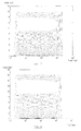
- Fig. 5 illustrates the ripple at high frequencies
- Fig. 6 shows the overall frequency response using a filterbank according to the present invention.
- an analog filter comprising a set of subfilters in parallel and a feedback loop
- Other structures are therefore preferred, such as a cascade structure, wherein a number of feed forward peak filters 1 are installed, as shown in fig. 1, each peak filter being active in a given frequency band around a center frequency.
- the desired peak gains at these center frequencies can be adjusted by the user of such a filter structure, for example by way of sliders.
- these set values are identical to the peak gain values imposed on each sub-filter in the cascade so that the mutual influence of these sub-filters is ignored.
- the present invention is related to a method of controlling such a filter structure by first calculating the necessary peak gain to be imposed on each sub-filter in order for the global frequency response function of the filter cascade to reach the desired peak gains at the center frequencies. This calculation, which forms the main characteristic of the invention, is based on the compensation of the mutual influence of the sub-filters.
- This calculation which forms the main characteristic of the invention, is based on the compensation of the mutual influence of the sub-filters.
- FIG. 2a The structure of an individual digital peak filter is shown in figure 2a. It consists of a band pass filter 10, combined with a unity throughput 11. The effect is a filter with a frequency response as shown in figure 2b, having unity gain on either side of the center frequency (regions 12, 13), and a gain higher than unity in a region 14 around the center frequency.
- Figure 3 shows the common case wherein the center frequencies of a cascade of peak filters are equidistant on a logarithmic frequency scale. The closer the center frequencies are lying together, and the broader the curves are (lower Q) the more mutual influence adjacent curves will exert on each other.
- OOB 'Out Of Band' gain
- the present invention proposes a method wherein all the n OOB values are taken into account, so that it is the interaction between the filters at their respective G p,bi values which eventually ensures that the desired set values are reached by the global transfer function.
- the method of the invention aims to derive a set of G p,bi values from a given set of G set,bi values.
- one set of n OOB values needs to be stored, in order to calculate each filter gain G p,bi on the basis of a given set of desired gains G set,bi .
- the present invention allows to remedy this problem, by using an iterative way of solving the system of equations.
- the unknown gains G p,bi are then calculated based on the OOB values corresponding to the known G p,bi values a given timespan earlier. This requires another parameter to be regarded, namely the 'old' value of the peak gain at a given moment : G p,biold .
- the 'new' values G p,bi are then recalculated from the known 'old' values, at each calculation step. This can be done in a number of fixed gain steps, for example every 0.5dB, until the new gain value is reached, or in a number of iterations starting from the maximum difference between old and new gain value, and recalculating until the new value is reached within an accurate interval.
- the asymmetry in the curves is taken into account in the method according to the present invention by so called 'table based compensation', meaning that the OOB values for the higher frequencies, e.g. starting from band 20 in the case of 30 bands, are derived from bandspecific tables, while for the lower frequencies, all OOB values are derived from tables which are valid for one band (e.g. f1).
- these Q-factors themselves may be regarded as unknowns, in which case the system (a) would become :
- a preferred embodiment of the invention works with a set of Q-factors which is constant during adaptation of the peak filters so that system (a) may be used to calculate the G p,bi values.
- the Q-factors may be changed manually, causing a whole new set of OOB values to be calculated and stored for that particular set of Q-factors and for every gain.
- system (a) will once again be used, but it will be based on the new set of OOB values. In that way, the Q-factors can be used to influence the ripple of the curves, although not during the setting of the gains.
- the architecture of a filtering device consists of three layers :
- the implementation layer is realised on a fixed point DSP.
- each filter section is made up of a cascade of two 2 nd order biquad peak filters as shown in figure 2a.
- the calculation layer is then preferably realised on a floating point DSP.
- both the implementation layer and the calculation layer are implemented on a floating point DSP. This may be done using two floating point DSP's, one for the implementation layer and one for the calculation layer, or with both layers implemented on one single floating point DSP.
- a floating point DSP is used for the implementation layer, one 2 nd order biquad filter is used in each filter section.
Landscapes
- Physics & Mathematics (AREA)
- Engineering & Computer Science (AREA)
- Computer Hardware Design (AREA)
- Mathematical Physics (AREA)
- Networks Using Active Elements (AREA)
Priority Applications (1)
| Application Number | Priority Date | Filing Date | Title |
|---|---|---|---|
| EP01870110A EP1263131A1 (de) | 2001-05-28 | 2001-05-28 | Filteranordnung und Verfahren zur Steuerung derselben |
Applications Claiming Priority (1)
| Application Number | Priority Date | Filing Date | Title |
|---|---|---|---|
| EP01870110A EP1263131A1 (de) | 2001-05-28 | 2001-05-28 | Filteranordnung und Verfahren zur Steuerung derselben |
Publications (1)
| Publication Number | Publication Date |
|---|---|
| EP1263131A1 true EP1263131A1 (de) | 2002-12-04 |
Family
ID=8184976
Family Applications (1)
| Application Number | Title | Priority Date | Filing Date |
|---|---|---|---|
| EP01870110A Withdrawn EP1263131A1 (de) | 2001-05-28 | 2001-05-28 | Filteranordnung und Verfahren zur Steuerung derselben |
Country Status (1)
| Country | Link |
|---|---|
| EP (1) | EP1263131A1 (de) |
Cited By (2)
| Publication number | Priority date | Publication date | Assignee | Title |
|---|---|---|---|---|
| EP1437828A3 (de) * | 2003-01-13 | 2007-10-24 | Rane Corporation | Vorrichtung und Prozesse zur Linearisierung von Interaktionen zwischen Filtern |
| WO2017075398A1 (en) | 2015-10-28 | 2017-05-04 | Jean-Marc Jot | Spectral correction of audio signals |
Citations (2)
| Publication number | Priority date | Publication date | Assignee | Title |
|---|---|---|---|---|
| US5687104A (en) * | 1995-11-17 | 1997-11-11 | Motorola, Inc. | Method and apparatus for generating decoupled filter parameters and implementing a band decoupled filter |
| US5714918A (en) * | 1995-08-12 | 1998-02-03 | Deutsche Itt Industries, Gmbh | Equalizer for digitized signals |
-
2001
- 2001-05-28 EP EP01870110A patent/EP1263131A1/de not_active Withdrawn
Patent Citations (2)
| Publication number | Priority date | Publication date | Assignee | Title |
|---|---|---|---|---|
| US5714918A (en) * | 1995-08-12 | 1998-02-03 | Deutsche Itt Industries, Gmbh | Equalizer for digitized signals |
| US5687104A (en) * | 1995-11-17 | 1997-11-11 | Motorola, Inc. | Method and apparatus for generating decoupled filter parameters and implementing a band decoupled filter |
Cited By (4)
| Publication number | Priority date | Publication date | Assignee | Title |
|---|---|---|---|---|
| EP1437828A3 (de) * | 2003-01-13 | 2007-10-24 | Rane Corporation | Vorrichtung und Prozesse zur Linearisierung von Interaktionen zwischen Filtern |
| WO2017075398A1 (en) | 2015-10-28 | 2017-05-04 | Jean-Marc Jot | Spectral correction of audio signals |
| CN108369494A (zh) * | 2015-10-28 | 2018-08-03 | Dts(英属维尔京群岛)有限公司 | 音频信号的频谱校正 |
| EP3369176A4 (de) * | 2015-10-28 | 2019-10-16 | DTS, Inc. | Spektrale korrektur von audiosignalen |
Similar Documents
| Publication | Publication Date | Title |
|---|---|---|
| EP1437828B1 (de) | Vorrichtung und Prozesse zur Linearisierung von Interaktionen zwischen Filtern | |
| CN115801508A (zh) | 基于自适应分段小数滤波与频域均衡的多通道校正方法 | |
| US11601309B1 (en) | Multi-stage continuous time linear equalizer with reconfigurable inductor scheme | |
| US3753140A (en) | Equalizing network | |
| US6988116B2 (en) | Method of designing polynomials for controlling the slewing of adaptive digital films | |
| US6492865B1 (en) | Band pass filter from two filters | |
| CN117997312A (zh) | 一种变步长自适应滤波方法及系统 | |
| Haridas et al. | Efficient Farrow structure based bank of variable bandwidth filters for digital hearing aids | |
| WO2001056156A1 (en) | Band pass filter with improved group delay | |
| US8542840B2 (en) | Apparatus and method for filtering a signal to match a loudspeaker | |
| Lanusse et al. | Tuning of an active suspension system using a fractional controller and a closed-loop tuning | |
| Alkire et al. | Interior-point methods for magnitude filter design | |
| CN114095836A (zh) | 音频处理装置及音频处理方法 | |
| US20070174376A1 (en) | Digital Filter Design System And Method | |
| CA1299678C (en) | Apparatus and method for adaptive amplitude equalization | |
| Barcellos et al. | Design of FIR filters combining the frequency-response masking and the WLS-Chebyshev approaches | |
| US6920471B2 (en) | Compensation scheme for reducing delay in a digital impedance matching circuit to improve return loss | |
| CN114900155B (zh) | 一种iir数字多通带滤波器设计方法 | |
| CN107171665B (zh) | 带通信号的双通道tiadc非线性系统参数估计方法 | |
| Jurišić et al. | Low-sensitivity, single-amplifier, active-rc allpole filters using tables | |
| Kurbiel et al. | Design of highly selective quasi-equiripple FIR lowpass filters with approximately linear phase and very lowgroup delay | |
| JPH05197775A (ja) | デジタルフィルタ回路の設計方法 | |
| JPS59119906A (ja) | 帰還増幅回路システム | |
| Zdunek | General design of ladder networks with arbitrarily distributed uniform losses between coils and capacitors | |
| Quirk et al. | On narrow-band spectrum calculation by direct decimation |
Legal Events
| Date | Code | Title | Description |
|---|---|---|---|
| PUAI | Public reference made under article 153(3) epc to a published international application that has entered the european phase |
Free format text: ORIGINAL CODE: 0009012 |
|
| AK | Designated contracting states |
Kind code of ref document: A1 Designated state(s): AT BE CH CY DE DK ES FI FR GB GR IE IT LI LU MC NL PT SE TR |
|
| AX | Request for extension of the european patent |
Free format text: AL;LT;LV;MK;RO;SI |
|
| 17P | Request for examination filed |
Effective date: 20030331 |
|
| AKX | Designation fees paid |
Designated state(s): BE DE FR GB |
|
| STAA | Information on the status of an ep patent application or granted ep patent |
Free format text: STATUS: THE APPLICATION IS DEEMED TO BE WITHDRAWN |
|
| 18D | Application deemed to be withdrawn |
Effective date: 20041201 |