EP1264074B1 - Dispositif d'intervention pour puits sous-marin, et procede et cable a utiliser avec ce dispositif - Google Patents
Dispositif d'intervention pour puits sous-marin, et procede et cable a utiliser avec ce dispositif Download PDFInfo
- Publication number
- EP1264074B1 EP1264074B1 EP01908485A EP01908485A EP1264074B1 EP 1264074 B1 EP1264074 B1 EP 1264074B1 EP 01908485 A EP01908485 A EP 01908485A EP 01908485 A EP01908485 A EP 01908485A EP 1264074 B1 EP1264074 B1 EP 1264074B1
- Authority
- EP
- European Patent Office
- Prior art keywords
- cable
- well
- vessel
- injector
- tool
- Prior art date
- Legal status (The legal status is an assumption and is not a legal conclusion. Google has not performed a legal analysis and makes no representation as to the accuracy of the status listed.)
- Expired - Lifetime
Links
Images




Classifications
-
- E—FIXED CONSTRUCTIONS
- E21—EARTH OR ROCK DRILLING; MINING
- E21B—EARTH OR ROCK DRILLING; OBTAINING OIL, GAS, WATER, SOLUBLE OR MELTABLE MATERIALS OR A SLURRY OF MINERALS FROM WELLS
- E21B33/00—Sealing or packing boreholes or wells
- E21B33/02—Surface sealing or packing
- E21B33/03—Well heads; Setting-up thereof
- E21B33/068—Well heads; Setting-up thereof having provision for introducing objects or fluids into, or removing objects from, wells
- E21B33/076—Well heads; Setting-up thereof having provision for introducing objects or fluids into, or removing objects from, wells specially adapted for underwater installations
-
- E—FIXED CONSTRUCTIONS
- E21—EARTH OR ROCK DRILLING; MINING
- E21B—EARTH OR ROCK DRILLING; OBTAINING OIL, GAS, WATER, SOLUBLE OR MELTABLE MATERIALS OR A SLURRY OF MINERALS FROM WELLS
- E21B19/00—Handling rods, casings, tubes or the like outside the borehole, e.g. in the derrick; Apparatus for feeding the rods or cables
- E21B19/002—Handling rods, casings, tubes or the like outside the borehole, e.g. in the derrick; Apparatus for feeding the rods or cables specially adapted for underwater drilling
-
- E—FIXED CONSTRUCTIONS
- E21—EARTH OR ROCK DRILLING; MINING
- E21B—EARTH OR ROCK DRILLING; OBTAINING OIL, GAS, WATER, SOLUBLE OR MELTABLE MATERIALS OR A SLURRY OF MINERALS FROM WELLS
- E21B19/00—Handling rods, casings, tubes or the like outside the borehole, e.g. in the derrick; Apparatus for feeding the rods or cables
- E21B19/22—Handling reeled pipe or rod units, e.g. flexible drilling pipes
-
- E—FIXED CONSTRUCTIONS
- E21—EARTH OR ROCK DRILLING; MINING
- E21B—EARTH OR ROCK DRILLING; OBTAINING OIL, GAS, WATER, SOLUBLE OR MELTABLE MATERIALS OR A SLURRY OF MINERALS FROM WELLS
- E21B7/00—Special methods or apparatus for drilling
- E21B7/12—Underwater drilling
- E21B7/124—Underwater drilling with underwater tool drive prime mover, e.g. portable drilling rigs for use on underwater floors
Definitions
- the invention relates to a device for intervention of a subsea well by means of a tool or the like suspended by a cable, fed from, respectively withdrawn to a vessel or the like, and driven by a drive mechanism located on the vessel, said device comprising a lubricator adapted to be located at a subsea Christmas tree in the well, and having a tool housing, for the insertion of the tool into the well, and sealing means, which encloses the cable in a slidable and sealed manner after the tool is inserted into the well.
- the invention relates to a method and a cable for use together with the device.
- Treatment of the well to increase the production rate or volume is made after a cost/benefit evaluation. Even if the production from a well may be increased by several factors, the intervention costs may become too high or the work considered too difficult and time consuming. For onshore or platform wells, having easy access into the Christmas tree and infrastructure in the form of lifting equipment etc., the costs of performing the well intervention will be less relatively to the benefit of the operations. An intervention of subsea wells is much more expensive. A vessel (drilling rig or the like) has to be used, involving large daily expenses and, in addition, time consuming transit to and from the field, and large costs as the work is much more time consuming. Because of this, the production volume from a platform or onshore well is up to twice the volume of a subsea well with similar reservoir conditions. As mentioned above, this is caused by the more easy access making a better programme for well maintenance practically possible and profitable.
- a well intervention may be difficult, as existing barriers have to be removed before entering the well. There are strict rules regarding which measures being required to prevent an uncontrolled blowout during such works. Thus, when well intervention shall be performed, a provisional pressure barrier has be established in the form of a blowout preventer. Depending on the work to be performed, this may vary from simple stop valves to large drilling BOPS.
- the vessel is positioned vertically above the well, i.e. mainly in an extension of the well axis. If an uncontrolled blowout should occur, the vessel may lose buoyancy due to the gas flowing to the surface from the well, resulting in loss of human lives.
- Another disadvantage of this position involves that the vessel must be provided with heave compensator means to balance wave motions during the operation.
- Coiled tubings are used during larger works and, in particular, when there is a need of performing circulation, as during stimulation of the well (chemical treatment or fracturing).
- the disadvantage is that this intervention type is very expencive as the use of a drilling rig is required.
- Wires are used when there is no need of circulation, e.g. during measurements. Wires may also be provided with conductors for power supply and signal transmission. Often, wires are used for the intervention due to their large rupture strength and, thereby, may be used when the tool is relatively heavy.
- the disadvantage of the wire is that a particular injector for grease (so-called “grease injector head”) must be used, by which grease under pressure is continuously injected to seal around the wire.
- the tool may be lowered in the well without discharge of oil and gas from the well while securing a pressure-proof barriere.
- this method requires large investments for equipments and materials, in particular grease. Therefore, large quantities of grease are consumed during this procedure.
- the used grease may not be directly discharged into the sea due to the risk of pollution and, therefore, it will normally be led to the vessel for a cleaning and possible recovery. As a result, the vessel has to be relatively large (and thereby expensive) due to all of the equipment located on the vessel.
- a string when the tool to be lowered is not too heavy, for example during sample collecting, a string may be used.
- the grease injector head mentioned above may be replaced by more simple sealing means, for example a so-called stuffing box.
- the stuffing box comprises a tubular sleeve of rubber or the like.
- the cable is tightly enclosed by the tubular sleeve in an extent preventing discharges but simultaneously without making the friction between the string and the sleeve too large. This is an inexpensive method of well intervention.
- US 4,730,677 discloses a method for servicing subsea wells with a flexible riser.
- the flexible riser eliminates the requirement for motion or heave compensating equipment
- US 5,671,811 discloses a vessel for injecting an inner continuous coiled tubing into an outer continuous coiled tubing which can be connected to a wellhead.
- US 4,899,823 discloses a method and apparatus for injecting coiled tubing into a submerged well. In the disclosed method an injector is attached to the well and the injector moves the coiled tubing through the well.
- a device for performing intervention on a subsea well from a floating vessel said well having a Christmas tree connected thereto, said device comprising a cable suspended from said vessel and extending to said well, a drive mechanism located at the vessel for selectively feeding and withdrawing said cable in response to movements of the vessel relative to the well, a lubricator adapted for placement on said Christmas tree, said lubricator comprising a tool housing for insertion of a tool into the well, and a sealing assembly for slidably and sealingly enclosing the cable as said cable passes therethrough, and a cable feed mechanism for selectively feeding said cable into the well and alternatively withdrawing said cable from the well, said cable feed mechanism being controlled independently of said drive mechanism.
- the cable feed mechanism comprises an injector located on said lubricator. In other embodiments the cable feed mechanism comprises a self-movable tractor fastened to said cable and disposed in the well.
- the invention relates to a method of use together with the present device, wherein the cable is driven in response to the movements of the vessel by the drive mechanism located on the vessel, and downwards in the well by the injector located on the lubricator, respectively the self-movable tractor fastened to the cable or tool, whereby the movement of the vessel is permitted from a position in extension of the well axis, and wherein the drive mechanism is controlled in a manner maintaining the cable in a slacked arc in the sea.
- An advantage of embodiments of the invention is that the vessel, to some extent, may be drifted by the weather and wind and, thereby, be adjusted to the varying conditions at the surface.
- the vessel may drift as far away as permitted by the length of the cable and/or umbilical.
- Different lengths of the cable and umbilical may be present in the sea. For example, during a situation in which the cable has to be cut, it will normally be sufficient of time to close all of the valves, detach the umbilical from the seabed in a controlled manner and withdraw this to the vessel. Vice versa, if the umbilical has a defect or has to be cut (involving that all of the valves in the lubricator and well have to be closed), it will normally be sufficient of time to withdraw the cable slack before this is cut.
- the cable may readily be fished out by means of a ROV, and the work continued when the dangerous situation has been remedied.
- a light vessel may be used.
- the injector is used together with the preferred lubricator, the unwanted fluids may be circulated in the well, as discussed in NO Patent No. 309439. This might result in great savings, as there is no need of large and heavy equipment for the treatment of the hydrocarbons on the vessel.
- the cable may be provided with friction at the same level as a string and, therefore, the use of a more simple type of sealing means is enabled.
- Fig. 1 a vessel 1 floating on a mass of water 2.
- the vessel has various equipment for controll, measurements, etc. well known in the field.
- the vessel is provided with heave compensator means and dynamic positioning (DP) means to keep the vessel in a correct position.
- DP dynamic positioning
- a Christmas tree 4 for a well 10 is situated at the seabed 3, which Christman tree is completed and made ready for production in accordance with standard practice.
- Produced oil and/or gas flowing upwards from the well is led through a pipeline 6 to a production facility, such as a production vessel.
- the vessel includes a tower 11 comprising a drive mechanism 12 for cable 9.
- the drive mechanism may be a motor-driven drum, which may unwind or wind the cable, although an injector located on the tower 11 is preferred, as indicated in Fig. 1.
- storing means 13 for a tool cable 9, and a storing drum 14 and storing drum 17 for an umbilical 16 and umbilical 7 for a subsea robot (ROV) 15, respectively, are located on the vessel.
- a lubricator assembly 5 is mounted at the top of the Christmas tree 4 in the well, providing controlled access into the well.
- a lubricator comprises a pressure controll assembly including valves to controll the well during the intervention procedure, a tool housing assembly comprising an insertion column for a tool or the like to be inserted into the well, and means for slidable but sealed leadthrough of the wire or string suspending the tool, i.e. a grease injector head or stuffing box.
- the components are removably connected to one another using connector means.
- the lubricator may be of a prior art type, for example as disclosed in US Patent No. 3.638.722, but is preferably of the type described in the applicants own NO Patent No. 309439, and it is referred to the latter for a further description of the lubricator.
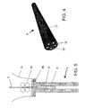
- Fig. 4 shows an embodiment of such a cable.
- the cable is manufactured of a fibre reinforced composite material, preferably glass or carbon fibre, in a vinyl ester matrix or, alternatively, of other plastics materials providing the required physical properties.
- An appropriate cable must have a low density in the range of 1-2 g/cm 3 but, preferably, not more than 1,5 g/cm 3 . This provides a cable having approximately neutral buoyancy in oil (i.e. in the well). The low density also results in more easy storing and transport of long cables because of a lower total weight. Moreover, the forces required to withdraw the cable (with the tool) from the well are reduced by the lower weight.
- the cable must have low thermal conductivity in the range of 0,25-0,35 W/mK, and low thermal expansion coefficient in the range of 0,00013 per °C.
- the rupture strength of the cable is about 46 kN, i.e in the same range as steel wires having the same external diameter, tensile strength in the range of 850-1600 MPa, and an elastic modulus in the range of 40000 (glass fibre) -135000 (carbon fibre) MPa.
- This flexibility provides a cable both being relatively rigid and windable on a drum for transport to and from the field (i.e. as a coiled tubing). Due to the rigidity of the cable, it may be pushed into the well having a low angle, or into a horizontal well (as a coiled tubing), which is impossible for wires or strings.
- the cable surface should have a friction coefficient of less than 0,2, preferably down to 0,1. For example, this is achieved by means of a cable coated by an external layer of a material having low friction coefficient.
- Fig. 4 shows an illustration of a cable 9, which shall be used together with the device tor performing intervention on a subsea well. It comprises a mass 20 having one or more encased metal threads or lines 19. The lines are used for control of the tool and signal transmission from it, and, preferably, they are protected by a jacket.
- the cable is coated by a material providing a external surface 21 with a low friction coefficient.
- Fig. 5 is an illustration of an upper part of a lubricator 5 mounted at the top of the well.
- the tool 8 suspended by the cable 9 is inserted into the well via a tool housing 25 in the lubricator, and a sealing assembly 40 seals around the cable.
- the sealing means shall be described hereinafter.
- a feed and drive mechanism 50 is located above the sealing means, and is intended to push the cable 9 into or withdraw it from the well, as also will be described further hereinafter.
- Means (not shown) securing the sealing means 40 during the use are located in the lubricator, which may include a funnel 26 to facilitate the insertion of the tool into the tool housing.
- the feed mechanism 50 comprises connecting means (not shown) for the connection at the top of the tool housing 25.
- the sealing means 40 are arranged in a spacing within the feed mechanism but might be situated in any desired position, for example within the tool housing, possibly also as a separate assembly connected between the feed mechanism and the tool housing.
- an endless belt or the like may be driven by one or more motors, as shown in Fig. 6a-c.
- the injector 350 comprises two main parts movably arranged in relation to a supporting beam 354. The two parts may be moved linearly towards and from the center line 90 by means of hydraulic actuators 374, 375.
- the two main parts are symmetrical.
- Upper 359a and lower 359b drive rollers are arranged in one of the main parts, and are rotated by one common or its own motor 361.
- a further free roller is arranged.
- a belt 365 runs above the rollers.
- the roller 367 may be provided with means to tighten the belt, for example the hydralic actuator 374, pressing the roller 367 from the center line 90, i.e. to the right in Fig. 6a.
- a counter plate 369 is located between the rollers 359a, b, and keeps the belts pressed against the cable in the area between the rollers 359, a, b.
- the other of the main parts 358 is identical to the first one of the main parts 357 but inverted in relation to this. Thus, it includes corresponding drive rollers 360a, 360b, 368 for a belt 366.
- the inside of the belts is formed with teeth for engagement with corresponding teeth on the drive rollers but may also have, for example, a frictional coating.
- the outside of the belts is preferably coated with a frictional coating of an appropriate material and is provided with a suitable groove (not shown) for the cable
- the main parts 357, 359 must be able to be moved radially out from the center, whereby the stuffing box migth be led through the injector.
- the motors are hydralically driven motors, as such are favourable for use in sea water, and a hydraulic medium is available via the umbilical. Possibly, these might be driven by sea water from a pump located in connection to the lubricator.
- An advantage of having hydraulic motors is that these might readily be coordinated to provide the same rotating velocity and torque.
- the motors might be of any desired type, for example electrical motors.
- the injector shown in Fig. 6a-c only is one of many alternatives appropriate for such an injector.
- an injector comprising at least one pair of drive rollers located on each side of the cable and intended to be in direct contact with this, and which can be moved from and towards the center line during the insertion of the tool into the well.
- the indicated injector may comprise another number of motors and drive rollers, and these may be located in another manner than shown, as well as more pairs of the drive belts.
- sealing means have to be provided, which are able to seal against the cable, avoiding discharge of hydrocarbons while keeping the friction between sealing/cable as low as possible, whereby the cable may slide through the sealing means.
- Fig. 7 shows an example of sealing means for use together with the device for performing intervention on a subsea well, which is denoted a stuffing box hereinafter.
- the stuffing box 40 comprises an external housing 80.
- the housing is of cylindrical shape but may be of polygonal shape, for example square.
- the housing 80 has a first lower portion 81 opening downwards to provide a hollow cylinder having a first internal diameter 84.
- the housing has a second upper portion 82, which in the same manner has the shape of a hollow cylinder.
- the portion 82 defines a first cavity 89, which is used as a spring chamber, and a second cavity having a second smaller internal diameter 83.
- the portion opens upwards.
- An end piece 85 is arranged at the end of the first portion, and defines a piston chamber together with the housing 80.
- the end piece 85 is fastened to the portion 81, for example by screws 86.
- the end piece 85 has a portion 87 providing a stub 87 facing upwards, and having an external diameter 88.
- a center bore 90 extends through the end piece.
- the bore has a first lower portion having an internal diameter 91, which enables the cable to pass with a small clearance, and a second upper portion having an internal diameter 92, which is larger than the first diameter and intended to receive a stuffing box sleeve.
- a piston 100 is movably arranged in the housing 80.
- the piston is shown as an annulus piston, and it has an external circumferential surface 101 intended for slidable engagement against the internal surface 84 of the skirt 81.
- the piston is extended upwards by a stub 103 having an external diameter 104 intended for slidable engagement against the surface 83.
- the piston with the stub is annular of shape, whereby a central axial cavity having an internal diameter 102 is defined, which is intended for slidable engagement against the stub 87.
- the piston may slide upwards and downwards within the housing 80.
- transmission pins 119 moving the piston 100 are arranged in the preferred embodiment. In Fig. 8 only two such pins are indicated but, of course, a number of pins may be equally distributed around the circumference. Thereby, the actuators moving the pins may be located outside the stuffing box.
- the piston may be actuated by supplying hydraulic fluid into the piston chamber 108. whereby the piston may be moved upwards into the upper position in the housing 80. If so, sealings, i.e. O-rings 125, 126, 127, must be located between the piston 100, housing 80 and end piece 85. In such a case means, i.e. connectors, have also to be provided for the supply of hydralic fluid, increasing the complexity.
- a sleeve 111 of an elastic material is removably arranged in a portion 92 of the bore 90.
- the sleeve is formed as a sealing sleeve intended to be pulled on the cable with a small clearance.
- the sleeve 111 has a hole 113 therethrough, in which the cable shall slide.
- the sleeve is manufactured of one piece, which is pulled on the cable before the use. However, it may consist of two semicylindrical parts having grooves in the planar surface, whereby it encloses the cable when the two halves are joined.
- the sleeve has an external diameter 112 slightly smaller than the internal diameter 112 of the portion 92.
- the sleeve is manufactured of an elastomer, such as rubber, for example of hydrogenated nitrile rubber.
- elastomer such as rubber
- Other materials may be thermoplastics, for example polyurethane or PTFE (TEFLON). The latter has particularly low frictional properties.
- a further sleeve 114 is located in the housing, and serves as a compression sleeve.
- the compression sleeve 114 has an internal bore therethrough having a larger diameter than the external diameter of the cable 9, whereby the cable may slide through the sleeve without hindrance.
- the compression sleeve 114 comprises a first portion 115 having an external diameter, whereby it may slide with a small clearance in the bore 91 of the bottom piece 85, and a second upper portion 116 having an external diameter slightly larger than the first portion.
- the sleeve has a flange 117 between these two portions having an external diameter which enables the flange to slide in a sealed manner within the stub 103 of the piston 100.
- a nut 128 is screwed inside the stub 103.
- a lock nut 129 is screwed on the nut 128 in order to lock this.
- a first spring 110 is located in the spring chamber 89, and is intended to force the piston into its lower position.
- a second spring 118 is located around the upper part of the compression sleeve. This spring rests on the flange 117, and it is affected by the nut 128.
- the spring 118 transmits its force to the flange 117 and, thereby, it provides a force directed at the top of the rubber sleeve via the first portion 115 of the compression sleeve.
- the axial pressure of the spring 118 against the upper surface of the sleeve 111 will provide a radial expansion of the sleeve, whereby this is pressed against the wall 92 and cable 9 and seals against both of these.
- the compression sleeve 114 When the piston 100 is situated in its upper position, the compression sleeve 114 is in its upper position and exerts no pressure against the sealing sleeve 111. The relief of the piston will involve that this will be pressed downwards by the spring 110. Because of this the spring 118 will press the compression sleeve 114 downwards against the sealing sleeve. Thus, the stuffing box exhibites a fail-safe function, whereby losses of the hydraulic pressure will result in a maximum sealing of the cable.
- the device comprises different measuring instruments monitoring the work, condition of the stuffing box, pressure and temperature, etc.
- a leakage detector monitoring whether hydrocabons leak through the sealing sleeve
- a frictional sensor measuring the friction between the cable and sealing sleeve.
- this may be intended to measure the force on the hydraulic motors.
- the measurement of the friction involves that the piston may be controlled, whereby the pressure exerted by the spring against the sealing sleeve is controlled. The pressure around the cable may thereby be adjusted.
- the spring and sleeve are selected from a material enabling achievement of an optimum sealing around the cable in the stuffing box.
- the stuffing box housing is provided with locking means, for example grooves or ridges, which cooperate with corresponding means in the device to maintain the stuffing box in a fixed position during use.
- locking means for example grooves or ridges, which cooperate with corresponding means in the device to maintain the stuffing box in a fixed position during use.
- the vessel is positioned to be situated approximately in the extension of the axis of the well 4. Moreover, it will normally be attempted to keep the vessel at this position during the operation, either by means of the anchors or dynamic positioning.
- the vessel 1 will be located straigthly above the well 4 only in a first stage of the work.
- the lubricator assembly 5 is lowered to the well and connected to the Christmas tree.
- the lubricator may be lowered as several components but, preferably, it will be made ready on the vessel, and lowered as an assembly. This results in the advantage of enabling the connectors to be pressure tested on the vessel.
- the umbilical 7 also is connected to the lubricator.
- the stuffing box and tool are made ready on the vessel.
- the cable 9 is led through the stuffing box and its free end is attached to the tool 8.
- the drive mechanism 12 is used to lower the stuffing box towards the lubricator, with the tool 8 suspended by the cable 9.
- the drive belts have been moved away from one another, whereby the tool and stuffing box may be inserted into the tool housing and the stuffing box locked for example fastened within the injector housing, as shown in Fig. 5. This and later operations are monitored by the ROV 15.
- the injector t ead is constructed in a manner enabling the components to be moved from one another and permitting the insertion of the stuffing box with the tool suspended by cable, and the locking to the injector housing or tool housing.
- Locking means such as pins, snap rings or the like, fasten the stuffing box during the work.
- the vessel is situated vertically above the well, as mentioned above, and the heave compensator on the vessel is used to secure a safe lowering. This is the situation shown in Fig. 1.
- the well is closed completely in this stage, i.e. all of the valves in the Christmas tree are closed.
- the vessel is moved away from this position, possibly by permitting the vessel to be drifted by the wind, whereby the vessel is moved away from the well while feeding the cable from the injector 12 and the umbilical from the drum 14.
- the movement is monitored and controlled from the vessel by means of the dynamic positioning.
- the controlled feeding is effected in such a manner holding the cable 9 (and possibly the umbilical 7) in a desired S-shaped arc where these extend between the vessel and the well (Fig. 2). This continues until the vessel is situated at a certain distance, for example about 200 meters, aside of the well.
- Fig. 2 is shown the situation during the intervention work itself.
- the vessel is situated at a distance from the well and the cable is hanging in an S-arc in the sea.
- the dynamic positioning reads the position of the vessel in relation to the well and signals whether the cable shall be fed or withdrawn, whereby this configuration might be maintained.
- valves in the Christmas tree may be opened.
- the injector 50 is started to push the tool downwards in the well.
- the drive mechanism 12 is started to feed the cable from the vessel.
- the desired S-curve of the cable is maintained by such a coordination of the two injectors.
- the injector 50 When the tool has reached the desired depth in the well, the injector 50 is stopped and the required measurements (or another operation) are performed. If the vessel should have been moved in relation to the well during this stage, the injector may be started to feed, respectively withdraw, the necessary length of the cable to maintain the desired S-curve in the sea.
- the cable extends in an S-curve in the sea, this first of all is due to practical reasons.
- the arc will provide a slack in the cable, whereby the movements of the vessel may be absorbed without subjecting the cable to strains which may result in rupture.
- the dynamic positioning system on the vessel has a response time which has to be taken into consideration.
- the injector is restarted to withdraw the cable.
- the drive mechanism 12 on the vessel and the drum 14 for the umbilical are started.
- the vessel also is aside of the well and the process is monitored, whereby the cable also now maintains the required S-curve.
- both of the injectors are stopped.
- the injector 12 on the vessel is only started if the vessel moves. Unwanted hydrocarbons may now be circulated out of the lubricator, as discussed in NO Patent No. 309439. Then, the valves of the Christmas tree and the lubricator are closed.
- the propulsion machinery of the vessel also is started to move the vessel backwards into a position straigthly above the well. Simultaneously, the injector 12 (and the drum 14) are driven to withdraw the cable and the umbilical. When the vessel again is situated straigthly above the well, the situation shown in Fig. 1 is re-established.
- the injector is opened and the stuffing box retrieved together with the tool. Both the cable and the sealing sleeve may thereby be inspected for wear and possible replacement. If another intervention type is required in the well, another tool may be attached to the cable, and the operation discussed above may be performed.
- the preferred cable has a large elastic modulus (larger rigidity), it may be pushed into sloping and horizontal wells. Because it is desired that the cable might be winded on a drum, it may not be too rigid. It may thereby be pushed longer into horizontal wells than a wire but there is a limit to how far it may be pushed. However, the described method may also be used in such cases.
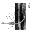
- the tool may be connected to a self-movable tractor 18 in stead of, or in addition to the injector 50 on the lubricator, as illustrated in Fig. 3. The movement of the tractor is coordinated with the injector on the vessel, in the same manner as by the use of two injectors. In deviation wells all of the shown feed mechanisms may possibly be used, using for example the injector 50 in the vertical portion while operating the tractor in the horizontal portion of the well.
Landscapes
- Engineering & Computer Science (AREA)
- Life Sciences & Earth Sciences (AREA)
- Geology (AREA)
- Mining & Mineral Resources (AREA)
- Physics & Mathematics (AREA)
- Environmental & Geological Engineering (AREA)
- Fluid Mechanics (AREA)
- General Life Sciences & Earth Sciences (AREA)
- Geochemistry & Mineralogy (AREA)
- Mechanical Engineering (AREA)
- Electrical Discharge Machining, Electrochemical Machining, And Combined Machining (AREA)
- Ropes Or Cables (AREA)
- Connector Housings Or Holding Contact Members (AREA)
- Processing Of Terminals (AREA)
- Earth Drilling (AREA)
- Lubricants (AREA)
- Bridges Or Land Bridges (AREA)
- Cable Accessories (AREA)
- Laying Of Electric Cables Or Lines Outside (AREA)
- Mechanical Operated Clutches (AREA)
- Electric Cable Installation (AREA)
- Aiming, Guidance, Guns With A Light Source, Armor, Camouflage, And Targets (AREA)
- Communication Cables (AREA)
Claims (20)
- Dispositif permettant d'effectuer une intervention sur un puits sous-marin (10) depuis un support flottant (1), un arbre de Noël (4) étant monté sur ledit puits, ledit dispositif comprenant un câble (9) suspendu audit support et s'étendant jusqu'au puits, un mécanisme d'entraînement (12) situé sur le support pour faire avancer et retirer sélectivement ledit câble en réponse aux mouvements du support par rapport au puits, un lubrificateur (5) adapté pour être placé sur ledit arbre de Noël (4), ledit lubrificateur comprenant un logement d'outil permettant l'insertion d'un outil (8) dans le puits, et un ensemble d'étanchéité (40) pour entourer le câble (9) de manière coulissante et de manière étanche lorsque ledit câble le traverse, et un mécanisme d'avance de câble pour, au choix, faire avancer le câble dans le puits et, alternativement, retirer le câble du puits, caractérisé en ce que ledit mécanisme d'avance de câble est commandé indépendamment dudit mécanisme d'entraînement.
- Dispositif selon la revendication 1, dans lequel ledit mécanisme d'avance de câble comprend un injecteur (50) situé sur ledit lubrificateur (5).
- Dispositif selon la revendication 1, dans lequel ledit mécanisme d'avance de câble comprend un tracteur (18) fixé audit câble (9) et placé dans le puits (10).
- Dispositif selon la revendication 1, dans lequel l'injecteur comprend au moins une paire de courroies sans fin (365, 366) pourvues chacune d'un galet d'entraînement (359, 360) entraîné par au moins un moteur hydraulique (361, 362).
- Dispositif selon la revendication 4, dans lequel l'injecteur comprend un moyen (374, 375) destiné à mettre les courroies en et hors de prise avec le câble.
- Dispositif selon la revendication 4 ou 5, dans lequel la courroie et le galet d'entraînement ont des dents qui coopèrent.
- Dispositif selon l'une quelconque des revendications 4 à 6, dans lequel la courroie comporte une rainure permettant la mise en prise avec le câble (9).
- Dispositif selon l'une quelconque des revendications précédentes, dans lequel le moyen d'étanchéité (40) comprend un élément de manchon élastique (111) permettant le guidage coulissant et étanche du câble (9).
- Dispositif selon la revendication 8, dans lequel l'élément de manchon est déformable dans le sens radial, grâce à quoi l'élément de manchon peut s'appliquer de manière étanche sur le câble lorsqu'un effort axial est exercé.
- Dispositif selon la revendication 8 ou 9, dans lequel un manchon de compression (114) est prévu, entraîné par un ressort (118) pour exercer un effort axial sur l'élément de manchon.
- Dispositif selon l'une quelconque des revendications 8 à 10, dans lequel un ensemble de piston (100) est prévu pour commander l'effort du ressort.
- Dispositif selon l'une quelconque des revendications précédentes, dans lequel le câble comprend une matière plastique (20) renforcée par des fibres de carbone ou de verre, grâce à quoi le câble atteint le degré de rigidité nécessaire, et un revêtement (21) fait d'un matériau ayant un faible coefficient de frottement.
- Dispositif selon la revendication 12, dans lequel le câble a un module d'élasticité compris dans l'intervalle de 40 000 à 130 000 MPa et un coefficient de frottement inférieur à 0,2.
- Dispositif selon la revendication 12 ou 13, dans lequel le câble comprend des lignes (19) permettant d'alimenter l'outil en énergie électrique.
- Dispositif selon la revendication 14, dans lequel les lignes électriques sont enfermées dans une gaine isolante.
- Procédé d'intervention sur un puits sous-marin (10) au moyen du dispositif de l'une quelconque des revendications 1 à 15, dans lequel le câble (9) est entraîné, en réponse aux mouvements du support (1), par le mécanisme d'entraînement (12) et, dans le puits, par l'injecteur (59 ; 350) situé sur le lubrificateur, respectivement le tracteur (18) fixé sur le câble (9) ou l'outil (8), grâce à quoi le mouvement du support (1) est permis depuis une position située dans le prolongement de l'axe (90) du puits (10), et dans lequel le mécanisme d'entraînement est commandé de manière à maintenir le câble en arc lâche dans la mer.
- Procédé selon la revendication 16, dans lequel le mécanisme d'entraînement et l'injecteur, respectivement le tracteur, sont entraînés à peu près à la même vitesse lorsque le support ne bouge pas.
- Procédé selon la revendication 16, dans lequel le mécanisme d'entraînement et l'injecteur, respectivement le tracteur, sont entraînés à des vitesses différentes lorsque l'on déplace le support par rapport au puits.
- Procédé selon la revendication 18, dans lequel le mécanisme d'entraînement est entraîné plus rapidement que l'injecteur, respectivement le tracteur, lorsque l'on éloigne le support du puits.
- Procédé selon la revendication 18, dans lequel le mécanisme d'entraînement est entraîné plus lentement que l'injecteur, respectivement le tracteur, lorsque l'on rapproche le support du puits.
Priority Applications (1)
| Application Number | Priority Date | Filing Date | Title |
|---|---|---|---|
| EP06123330A EP1760252A1 (fr) | 2000-02-21 | 2001-02-20 | Dispositif d'intervention pour puits sous-marin, et procédé et cable à utiliser avec ce dispositif |
Applications Claiming Priority (3)
| Application Number | Priority Date | Filing Date | Title |
|---|---|---|---|
| NO20000836 | 2000-02-21 | ||
| NO20000836A NO315386B1 (no) | 2000-02-21 | 2000-02-21 | Anordning og fremgangsmåte for intervensjon i en undersjöisk brönn |
| PCT/NO2001/000061 WO2001061145A1 (fr) | 2000-02-21 | 2001-02-20 | Dispositif d'intervention pour puits sous-marin, et procede et cable a utiliser avec ce dispositif |
Related Child Applications (1)
| Application Number | Title | Priority Date | Filing Date |
|---|---|---|---|
| EP06123330A Division EP1760252A1 (fr) | 2000-02-21 | 2001-02-20 | Dispositif d'intervention pour puits sous-marin, et procédé et cable à utiliser avec ce dispositif |
Publications (2)
| Publication Number | Publication Date |
|---|---|
| EP1264074A1 EP1264074A1 (fr) | 2002-12-11 |
| EP1264074B1 true EP1264074B1 (fr) | 2007-01-03 |
Family
ID=19910764
Family Applications (2)
| Application Number | Title | Priority Date | Filing Date |
|---|---|---|---|
| EP06123330A Withdrawn EP1760252A1 (fr) | 2000-02-21 | 2001-02-20 | Dispositif d'intervention pour puits sous-marin, et procédé et cable à utiliser avec ce dispositif |
| EP01908485A Expired - Lifetime EP1264074B1 (fr) | 2000-02-21 | 2001-02-20 | Dispositif d'intervention pour puits sous-marin, et procede et cable a utiliser avec ce dispositif |
Family Applications Before (1)
| Application Number | Title | Priority Date | Filing Date |
|---|---|---|---|
| EP06123330A Withdrawn EP1760252A1 (fr) | 2000-02-21 | 2001-02-20 | Dispositif d'intervention pour puits sous-marin, et procédé et cable à utiliser avec ce dispositif |
Country Status (10)
| Country | Link |
|---|---|
| US (1) | US6843321B2 (fr) |
| EP (2) | EP1760252A1 (fr) |
| AT (1) | ATE350563T1 (fr) |
| AU (2) | AU2001236226B2 (fr) |
| BR (1) | BR0108573B1 (fr) |
| CA (1) | CA2400001C (fr) |
| DE (1) | DE60125731D1 (fr) |
| DK (1) | DK1264074T3 (fr) |
| NO (1) | NO315386B1 (fr) |
| WO (1) | WO2001061145A1 (fr) |
Families Citing this family (59)
| Publication number | Priority date | Publication date | Assignee | Title |
|---|---|---|---|---|
| US6488093B2 (en) | 2000-08-11 | 2002-12-03 | Exxonmobil Upstream Research Company | Deep water intervention system |
| US6808021B2 (en) * | 2000-08-14 | 2004-10-26 | Schlumberger Technology Corporation | Subsea intervention system |
| US7779916B2 (en) * | 2000-08-14 | 2010-08-24 | Schlumberger Technology Corporation | Apparatus for subsea intervention |
| US6763889B2 (en) | 2000-08-14 | 2004-07-20 | Schlumberger Technology Corporation | Subsea intervention |
| US6591913B2 (en) * | 2001-12-12 | 2003-07-15 | Oceaneering International, Inc. | System and method for lessening impact on Christmas trees during downhole operations involving Christmas trees |
| US7165619B2 (en) * | 2002-02-19 | 2007-01-23 | Varco I/P, Inc. | Subsea intervention system, method and components thereof |
| EP1540130B1 (fr) | 2002-06-28 | 2015-01-14 | Vetco Gray Scandinavia AS | Appareillage et procede d'intervention dans un forage en mer |
| AU2003260015B2 (en) * | 2002-08-22 | 2007-12-06 | Fmc Technologies, Inc. | Apparatus and method for installation of subsea well completion systems |
| US7380589B2 (en) * | 2002-12-13 | 2008-06-03 | Varco Shaffer, Inc. | Subsea coiled tubing injector with pressure compensation |
| GB2417656B (en) * | 2004-08-24 | 2009-02-11 | Vetco Gray Controls Ltd | Communication apparatus |
| US8413723B2 (en) * | 2006-01-12 | 2013-04-09 | Schlumberger Technology Corporation | Methods of using enhanced wellbore electrical cables |
| NO323342B1 (no) * | 2005-02-15 | 2007-04-02 | Well Intervention Solutions As | System og fremgangsmate for bronnintervensjon i sjobunnsinstallerte olje- og gassbronner |
| US7308934B2 (en) * | 2005-02-18 | 2007-12-18 | Fmc Technologies, Inc. | Fracturing isolation sleeve |
| US7225877B2 (en) * | 2005-04-05 | 2007-06-05 | Varco I/P, Inc. | Subsea intervention fluid transfer system |
| WO2007009246A1 (fr) * | 2005-07-19 | 2007-01-25 | Tesco Corporation | Reduction d'entree de cable de forage |
| US7416025B2 (en) * | 2005-08-30 | 2008-08-26 | Kellogg Brown & Root Llc | Subsea well communications apparatus and method using variable tension large offset risers |
| US7845412B2 (en) * | 2007-02-06 | 2010-12-07 | Schlumberger Technology Corporation | Pressure control with compliant guide |
| MX2009010195A (es) * | 2007-03-26 | 2010-03-22 | Schlumberger Technology Bv | Sistema y metodo para realizar operaciones de intervencion con una herramienta submarina en forma de y. |
| GB2456772A (en) * | 2008-01-22 | 2009-07-29 | Schlumberger Holdings | Deployment of a dynamic seal in an intervention procedure |
| US8047295B2 (en) * | 2007-04-24 | 2011-11-01 | Fmc Technologies, Inc. | Lightweight device for remote subsea wireline intervention |
| US7926579B2 (en) * | 2007-06-19 | 2011-04-19 | Schlumberger Technology Corporation | Apparatus for subsea intervention |
| NO20073832L (no) | 2007-07-20 | 2009-01-21 | Fmc Kongsberg Subsea As | Komposittkabel |
| MX2010005555A (es) * | 2007-11-20 | 2010-11-12 | Keith K Millheim | Embarcacion de despliegue de tuberia continua en altamar. |
| US20090151956A1 (en) * | 2007-12-12 | 2009-06-18 | John Johansen | Grease injection system for riserless light well intervention |
| US8697992B2 (en) | 2008-02-01 | 2014-04-15 | Schlumberger Technology Corporation | Extended length cable assembly for a hydrocarbon well application |
| US20090260830A1 (en) * | 2008-04-18 | 2009-10-22 | Henning Hansen | Rigless well completion method |
| US8439109B2 (en) * | 2008-05-23 | 2013-05-14 | Schlumberger Technology Corporation | System and method for depth measurement and correction during subsea intervention operations |
| US9534453B2 (en) * | 2008-08-13 | 2017-01-03 | Onesubsea Ip Uk Limited | Umbilical management system and method for subsea well intervention |
| US8316947B2 (en) * | 2008-08-14 | 2012-11-27 | Schlumberger Technology Corporation | System and method for deployment of a subsea well intervention system |
| US9412492B2 (en) | 2009-04-17 | 2016-08-09 | Schlumberger Technology Corporation | Torque-balanced, gas-sealed wireline cables |
| US11387014B2 (en) | 2009-04-17 | 2022-07-12 | Schlumberger Technology Corporation | Torque-balanced, gas-sealed wireline cables |
| US12163394B2 (en) | 2009-04-17 | 2024-12-10 | Schlumberger Technology Corporation | Reduced torque wireline cable |
| GB0908279D0 (en) * | 2009-05-14 | 2009-06-24 | Enovate Systems Ltd | Subsea winch |
| EP2480750A2 (fr) | 2009-09-22 | 2012-08-01 | Schlumberger Technology B.V. | Cable metallique destine a l'utilisation avec des ensembles tracteurs de forage |
| US20110168401A1 (en) * | 2010-01-11 | 2011-07-14 | Halliburton Energy Services, Inc. | Electric Subsea Coiled Tubing Injector Apparatus |
| GB201004481D0 (en) * | 2010-03-18 | 2010-05-05 | Viking Intervention Technology | Injector head |
| US8720582B2 (en) | 2010-05-19 | 2014-05-13 | Baker Hughes Incorporated | Apparatus and methods for providing tubing into a subsea well |
| US8534366B2 (en) | 2010-06-04 | 2013-09-17 | Zeitecs B.V. | Compact cable suspended pumping system for lubricator deployment |
| GB201014035D0 (en) * | 2010-08-20 | 2010-10-06 | Well Integrity Solutions As | Well intervention |
| US20120193104A1 (en) * | 2011-02-01 | 2012-08-02 | Corey Eugene Hoffman | Coiled tubing module for riserless subsea well intervention system |
| US8857520B2 (en) * | 2011-04-27 | 2014-10-14 | Wild Well Control, Inc. | Emergency disconnect system for riserless subsea well intervention system |
| US8960301B2 (en) | 2011-08-22 | 2015-02-24 | Halliburton Energy Services, Inc. | Completing underwater wells |
| NO334144B1 (no) * | 2011-09-12 | 2013-12-16 | Aker Subsea As | Roterende undervannsinnretning |
| US9651138B2 (en) | 2011-09-30 | 2017-05-16 | Mtd Products Inc. | Speed control assembly for a self-propelled walk-behind lawn mower |
| KR101390380B1 (ko) | 2012-04-20 | 2014-04-30 | 삼성중공업 주식회사 | 유체 수송 장치 및 이를 이용한 유체 수송 방법 |
| US20140102721A1 (en) * | 2012-10-11 | 2014-04-17 | Zeitecs B.V. | Cable injector for deploying artificial lift system |
| DK2909843T3 (en) * | 2012-10-18 | 2017-01-09 | C6 Tech As | Fiber Composite Stake Oil Well Intervention Power Cable |
| NO341843B1 (no) * | 2014-03-25 | 2018-02-05 | Aker Solutions As | Et flerbruksverktøy for stigerørløs intervensjon av en undervannsbrønn samt metode for installering og fjerning av et ventiltre ved bruk av verktøyet |
| US9822613B2 (en) * | 2016-03-09 | 2017-11-21 | Oceaneering International, Inc. | System and method for riserless subsea well interventions |
| CN105840122B (zh) * | 2016-05-12 | 2017-12-08 | 山东科瑞机械制造有限公司 | 一种四马达交替驱动连续管注入头 |
| WO2018004040A1 (fr) * | 2016-07-01 | 2018-01-04 | Latticetechnology Co., Ltd. | Robot et procédé d'installation de système de régulation de pression de fond marin |
| NO344558B1 (en) * | 2017-11-12 | 2020-02-03 | Coilhose As | A method of well intervention. |
| CN114127604A (zh) | 2019-06-28 | 2022-03-01 | 斯伦贝谢技术有限公司 | 绞合光纤电缆 |
| US11230895B1 (en) * | 2020-09-30 | 2022-01-25 | Oceaneering International, Inc. | Open water coiled tubing control system |
| EP4352562A4 (fr) | 2021-06-10 | 2025-04-16 | Services Pétroliers Schlumberger | Câbles métalliques électro-optiques |
| WO2023023010A1 (fr) * | 2021-08-16 | 2023-02-23 | Schlumberger Technology Corporation | Systèmes et procédés utilisant un treuil sous-marin motorisé compact |
| US11905795B1 (en) * | 2022-10-06 | 2024-02-20 | Saudi Arabian Oil Company | Coiled tubing snap arrestor |
| CN116146179B (zh) * | 2023-02-14 | 2024-04-02 | 陕西航天德林科技集团有限公司 | 碳纤维杆式测井电缆注入系统及工艺 |
| NO20240437A1 (en) * | 2024-05-03 | 2025-11-04 | Archer Oiltools As | Subsea cut and pull method |
Family Cites Families (27)
| Publication number | Priority date | Publication date | Assignee | Title |
|---|---|---|---|---|
| US3568767A (en) * | 1969-01-23 | 1971-03-09 | Lockheed Aircraft Corp | Telescoping wireline lubricator |
| US3602300A (en) * | 1969-06-30 | 1971-08-31 | Westinghouse Electric Corp | Down-hole installation, recovery, and maintenance tool for wells |
| US3638722A (en) * | 1969-12-11 | 1972-02-01 | Mobil Oil Corp | Method and apparatus for reentry of subsea wellheads |
| GB8401315D0 (en) * | 1984-01-18 | 1984-02-22 | Graser J A | Wireline apparatus |
| GB8428633D0 (en) | 1984-11-13 | 1984-12-19 | British Petroleum Co Plc | Subsea wireline lubricator |
| US4730677A (en) * | 1986-12-22 | 1988-03-15 | Otis Engineering Corporation | Method and system for maintenance and servicing of subsea wells |
| US4825953A (en) | 1988-02-01 | 1989-05-02 | Otis Engineering Corporation | Well servicing system |
| GB2222842B (en) * | 1988-09-16 | 1992-07-15 | Otis Eng Co | Method and apparatus for running coiled tubing in subsea wells |
| GB8904295D0 (en) * | 1989-02-24 | 1989-04-12 | Framo Dev Ltd | Undersea package and installation system |
| US5234058A (en) * | 1990-03-15 | 1993-08-10 | Conoco Inc. | Composite rod-stiffened spoolable cable with conductors |
| US5908049A (en) * | 1990-03-15 | 1999-06-01 | Fiber Spar And Tube Corporation | Spoolable composite tubular member with energy conductors |
| FR2683591B1 (fr) * | 1991-11-13 | 1993-12-31 | Institut Francais Petrole | Dispositif de mesure et d'intervention dans un forage et utilisation dans un puits petrolier. |
| US5437899A (en) * | 1992-07-14 | 1995-08-01 | Composite Development Corporation | Structural element formed of a fiber reinforced thermoplastic material and method of manufacture |
| GB9500954D0 (en) * | 1995-01-18 | 1995-03-08 | Head Philip | A method of accessing a sub sea oil well and apparatus therefor |
| US6116345A (en) * | 1995-03-10 | 2000-09-12 | Baker Hughes Incorporated | Tubing injection systems for oilfield operations |
| US5553668A (en) * | 1995-07-28 | 1996-09-10 | Halliburton Company | Twin carriage tubing injector apparatus |
| US5921285A (en) * | 1995-09-28 | 1999-07-13 | Fiberspar Spoolable Products, Inc. | Composite spoolable tube |
| AU730344B2 (en) * | 1996-04-19 | 2001-03-08 | Baker Hughes Incorporated | Tubing injection systems for land and under water use |
| GB9626021D0 (en) * | 1996-12-14 | 1997-01-29 | Head Philip F | A riser system for a sub sea well and method of operation |
| FR2769665B1 (fr) * | 1997-10-13 | 2000-03-10 | Inst Francais Du Petrole | Methode et systeme de mesure dans un conduit horizontal |
| GB9802421D0 (en) * | 1998-02-06 | 1998-04-01 | Head Philip | A riser system for sub sea wells and method of operation |
| US6415877B1 (en) * | 1998-07-15 | 2002-07-09 | Deep Vision Llc | Subsea wellbore drilling system for reducing bottom hole pressure |
| US6102125A (en) * | 1998-08-06 | 2000-08-15 | Abb Vetco Gray Inc. | Coiled tubing workover riser |
| US6386290B1 (en) * | 1999-01-19 | 2002-05-14 | Colin Stuart Headworth | System for accessing oil wells with compliant guide and coiled tubing |
| GB9915141D0 (en) * | 1999-06-30 | 1999-09-01 | Read Well Services Limited | Cable |
| NO309439B1 (no) | 1999-10-01 | 2001-01-29 | Kongsberg Offshore As | Anordning ved undervanns lubrikator, samt fremgangsmåter for utsirkulering av fluider fra den samme |
| US6591913B2 (en) * | 2001-12-12 | 2003-07-15 | Oceaneering International, Inc. | System and method for lessening impact on Christmas trees during downhole operations involving Christmas trees |
-
2000
- 2000-02-21 NO NO20000836A patent/NO315386B1/no not_active IP Right Cessation
-
2001
- 2001-02-20 WO PCT/NO2001/000061 patent/WO2001061145A1/fr not_active Ceased
- 2001-02-20 AU AU2001236226A patent/AU2001236226B2/en not_active Expired
- 2001-02-20 DK DK01908485T patent/DK1264074T3/da active
- 2001-02-20 AT AT01908485T patent/ATE350563T1/de not_active IP Right Cessation
- 2001-02-20 CA CA002400001A patent/CA2400001C/fr not_active Expired - Lifetime
- 2001-02-20 EP EP06123330A patent/EP1760252A1/fr not_active Withdrawn
- 2001-02-20 BR BRPI0108573-5A patent/BR0108573B1/pt not_active IP Right Cessation
- 2001-02-20 DE DE60125731T patent/DE60125731D1/de not_active Expired - Lifetime
- 2001-02-20 AU AU3622601A patent/AU3622601A/xx active Pending
- 2001-02-20 US US10/204,606 patent/US6843321B2/en not_active Expired - Lifetime
- 2001-02-20 EP EP01908485A patent/EP1264074B1/fr not_active Expired - Lifetime
Also Published As
| Publication number | Publication date |
|---|---|
| EP1760252A1 (fr) | 2007-03-07 |
| CA2400001A1 (fr) | 2001-08-23 |
| ATE350563T1 (de) | 2007-01-15 |
| US6843321B2 (en) | 2005-01-18 |
| CA2400001C (fr) | 2008-07-08 |
| AU3622601A (en) | 2001-08-27 |
| AU2001236226B2 (en) | 2006-05-18 |
| US20030155127A1 (en) | 2003-08-21 |
| NO20000836L (no) | 2001-08-22 |
| BR0108573A (pt) | 2002-11-19 |
| EP1264074A1 (fr) | 2002-12-11 |
| WO2001061145A1 (fr) | 2001-08-23 |
| BR0108573B1 (pt) | 2009-05-05 |
| NO315386B1 (no) | 2003-08-25 |
| DE60125731D1 (de) | 2007-02-15 |
| NO20000836D0 (no) | 2000-02-21 |
| DK1264074T3 (da) | 2007-05-07 |
Similar Documents
| Publication | Publication Date | Title |
|---|---|---|
| US6843321B2 (en) | Intervention device for a subsea well, and method and cable for use with the device | |
| AU2001236226A1 (en) | Intervention device for a subsea well, and method and cable for use with the device | |
| US7431092B2 (en) | Assembly and method for intervention of a subsea well | |
| AU2003286632B2 (en) | Method and apparatus for installing control lines in a well | |
| CA2704629C (fr) | Systeme de colonne montante comprenant des moyens de commande de pression | |
| CA2685021C (fr) | Joint d'etancheite pour un train de tiges de forage | |
| AU2013356776B2 (en) | Radial clamping/sealing system and drilling system provided therewith for (semi)-continuous drilling a borehole, drilling rig comprising such system, and method there for | |
| WO2012106452A2 (fr) | Module de tube spiralé pour système d'intervention de puits sous-marin sans colonne montante | |
| US10920521B2 (en) | Self-contained well intervention system and method | |
| US8875798B2 (en) | Wellsite replacement system and method for using same | |
| US5944099A (en) | Infuser for composite spoolable pipe | |
| AU730344B2 (en) | Tubing injection systems for land and under water use | |
| AU2019362382B2 (en) | Well intervention apparatus and method | |
| US20100314122A1 (en) | Method and system for subsea intervention using a dynamic seal | |
| NO317227B1 (no) | Sammenstilling og fremgangsmate for intervensjon av en undersjoisk bronn |
Legal Events
| Date | Code | Title | Description |
|---|---|---|---|
| PUAI | Public reference made under article 153(3) epc to a published international application that has entered the european phase |
Free format text: ORIGINAL CODE: 0009012 |
|
| 17P | Request for examination filed |
Effective date: 20020903 |
|
| AK | Designated contracting states |
Kind code of ref document: A1 Designated state(s): AT BE CH CY DE DK ES FI FR GB GR IE IT LI LU MC NL PT SE TR |
|
| AX | Request for extension of the european patent |
Free format text: AL;LT;LV;MK;RO;SI |
|
| 17Q | First examination report despatched |
Effective date: 20050523 |
|
| GRAP | Despatch of communication of intention to grant a patent |
Free format text: ORIGINAL CODE: EPIDOSNIGR1 |
|
| GRAS | Grant fee paid |
Free format text: ORIGINAL CODE: EPIDOSNIGR3 |
|
| GRAA | (expected) grant |
Free format text: ORIGINAL CODE: 0009210 |
|
| AK | Designated contracting states |
Kind code of ref document: B1 Designated state(s): AT BE CH CY DE DK ES FI FR GB GR IE IT LI LU MC NL PT SE TR |
|
| PG25 | Lapsed in a contracting state [announced via postgrant information from national office to epo] |
Ref country code: FI Free format text: LAPSE BECAUSE OF FAILURE TO SUBMIT A TRANSLATION OF THE DESCRIPTION OR TO PAY THE FEE WITHIN THE PRESCRIBED TIME-LIMIT Effective date: 20070103 Ref country code: CH Free format text: LAPSE BECAUSE OF FAILURE TO SUBMIT A TRANSLATION OF THE DESCRIPTION OR TO PAY THE FEE WITHIN THE PRESCRIBED TIME-LIMIT Effective date: 20070103 Ref country code: NL Free format text: LAPSE BECAUSE OF FAILURE TO SUBMIT A TRANSLATION OF THE DESCRIPTION OR TO PAY THE FEE WITHIN THE PRESCRIBED TIME-LIMIT Effective date: 20070103 Ref country code: LI Free format text: LAPSE BECAUSE OF FAILURE TO SUBMIT A TRANSLATION OF THE DESCRIPTION OR TO PAY THE FEE WITHIN THE PRESCRIBED TIME-LIMIT Effective date: 20070103 Ref country code: AT Free format text: LAPSE BECAUSE OF FAILURE TO SUBMIT A TRANSLATION OF THE DESCRIPTION OR TO PAY THE FEE WITHIN THE PRESCRIBED TIME-LIMIT Effective date: 20070103 |
|
| REG | Reference to a national code |
Ref country code: GB Ref legal event code: FG4D |
|
| REF | Corresponds to: |
Ref document number: 60125731 Country of ref document: DE Date of ref document: 20070215 Kind code of ref document: P |
|
| REG | Reference to a national code |
Ref country code: IE Ref legal event code: FG4D |
|
| PG25 | Lapsed in a contracting state [announced via postgrant information from national office to epo] |
Ref country code: MC Free format text: LAPSE BECAUSE OF NON-PAYMENT OF DUE FEES Effective date: 20070228 |
|
| PG25 | Lapsed in a contracting state [announced via postgrant information from national office to epo] |
Ref country code: SE Free format text: LAPSE BECAUSE OF FAILURE TO SUBMIT A TRANSLATION OF THE DESCRIPTION OR TO PAY THE FEE WITHIN THE PRESCRIBED TIME-LIMIT Effective date: 20070403 |
|
| PG25 | Lapsed in a contracting state [announced via postgrant information from national office to epo] |
Ref country code: ES Free format text: LAPSE BECAUSE OF FAILURE TO SUBMIT A TRANSLATION OF THE DESCRIPTION OR TO PAY THE FEE WITHIN THE PRESCRIBED TIME-LIMIT Effective date: 20070414 |
|
| REG | Reference to a national code |
Ref country code: DK Ref legal event code: T3 |
|
| PG25 | Lapsed in a contracting state [announced via postgrant information from national office to epo] |
Ref country code: PT Free format text: LAPSE BECAUSE OF FAILURE TO SUBMIT A TRANSLATION OF THE DESCRIPTION OR TO PAY THE FEE WITHIN THE PRESCRIBED TIME-LIMIT Effective date: 20070604 |
|
| NLV1 | Nl: lapsed or annulled due to failure to fulfill the requirements of art. 29p and 29m of the patents act | ||
| ET | Fr: translation filed | ||
| REG | Reference to a national code |
Ref country code: CH Ref legal event code: PL |
|
| PLBE | No opposition filed within time limit |
Free format text: ORIGINAL CODE: 0009261 |
|
| STAA | Information on the status of an ep patent application or granted ep patent |
Free format text: STATUS: NO OPPOSITION FILED WITHIN TIME LIMIT |
|
| 26N | No opposition filed |
Effective date: 20071005 |
|
| PG25 | Lapsed in a contracting state [announced via postgrant information from national office to epo] |
Ref country code: BE Free format text: LAPSE BECAUSE OF FAILURE TO SUBMIT A TRANSLATION OF THE DESCRIPTION OR TO PAY THE FEE WITHIN THE PRESCRIBED TIME-LIMIT Effective date: 20070103 |
|
| PG25 | Lapsed in a contracting state [announced via postgrant information from national office to epo] |
Ref country code: IE Free format text: LAPSE BECAUSE OF NON-PAYMENT OF DUE FEES Effective date: 20070220 Ref country code: DE Free format text: LAPSE BECAUSE OF FAILURE TO SUBMIT A TRANSLATION OF THE DESCRIPTION OR TO PAY THE FEE WITHIN THE PRESCRIBED TIME-LIMIT Effective date: 20070404 |
|
| PG25 | Lapsed in a contracting state [announced via postgrant information from national office to epo] |
Ref country code: GR Free format text: LAPSE BECAUSE OF FAILURE TO SUBMIT A TRANSLATION OF THE DESCRIPTION OR TO PAY THE FEE WITHIN THE PRESCRIBED TIME-LIMIT Effective date: 20070404 |
|
| PG25 | Lapsed in a contracting state [announced via postgrant information from national office to epo] |
Ref country code: CY Free format text: LAPSE BECAUSE OF FAILURE TO SUBMIT A TRANSLATION OF THE DESCRIPTION OR TO PAY THE FEE WITHIN THE PRESCRIBED TIME-LIMIT Effective date: 20070103 |
|
| PG25 | Lapsed in a contracting state [announced via postgrant information from national office to epo] |
Ref country code: LU Free format text: LAPSE BECAUSE OF NON-PAYMENT OF DUE FEES Effective date: 20070220 |
|
| PG25 | Lapsed in a contracting state [announced via postgrant information from national office to epo] |
Ref country code: TR Free format text: LAPSE BECAUSE OF FAILURE TO SUBMIT A TRANSLATION OF THE DESCRIPTION OR TO PAY THE FEE WITHIN THE PRESCRIBED TIME-LIMIT Effective date: 20070103 |
|
| REG | Reference to a national code |
Ref country code: FR Ref legal event code: PLFP Year of fee payment: 16 |
|
| REG | Reference to a national code |
Ref country code: FR Ref legal event code: PLFP Year of fee payment: 17 |
|
| REG | Reference to a national code |
Ref country code: FR Ref legal event code: PLFP Year of fee payment: 18 |
|
| PGFP | Annual fee paid to national office [announced via postgrant information from national office to epo] |
Ref country code: DK Payment date: 20180212 Year of fee payment: 18 |
|
| PGFP | Annual fee paid to national office [announced via postgrant information from national office to epo] |
Ref country code: IT Payment date: 20180221 Year of fee payment: 18 |
|
| REG | Reference to a national code |
Ref country code: DK Ref legal event code: EBP Effective date: 20190228 |
|
| PG25 | Lapsed in a contracting state [announced via postgrant information from national office to epo] |
Ref country code: DK Free format text: LAPSE BECAUSE OF NON-PAYMENT OF DUE FEES Effective date: 20190228 |
|
| PG25 | Lapsed in a contracting state [announced via postgrant information from national office to epo] |
Ref country code: IT Free format text: LAPSE BECAUSE OF NON-PAYMENT OF DUE FEES Effective date: 20190220 |
|
| PGFP | Annual fee paid to national office [announced via postgrant information from national office to epo] |
Ref country code: GB Payment date: 20200212 Year of fee payment: 20 |
|
| PGFP | Annual fee paid to national office [announced via postgrant information from national office to epo] |
Ref country code: FR Payment date: 20200113 Year of fee payment: 20 |
|
| REG | Reference to a national code |
Ref country code: GB Ref legal event code: PE20 Expiry date: 20210219 |
|
| PG25 | Lapsed in a contracting state [announced via postgrant information from national office to epo] |
Ref country code: GB Free format text: LAPSE BECAUSE OF EXPIRATION OF PROTECTION Effective date: 20210219 |