EP1264078B1 - Turbocompresseur a geometrie variable - Google Patents
Turbocompresseur a geometrie variable Download PDFInfo
- Publication number
- EP1264078B1 EP1264078B1 EP00917890A EP00917890A EP1264078B1 EP 1264078 B1 EP1264078 B1 EP 1264078B1 EP 00917890 A EP00917890 A EP 00917890A EP 00917890 A EP00917890 A EP 00917890A EP 1264078 B1 EP1264078 B1 EP 1264078B1
- Authority
- EP
- European Patent Office
- Prior art keywords
- unison ring
- crank shaft
- vanes
- slots
- piston
- Prior art date
- Legal status (The legal status is an assumption and is not a legal conclusion. Google has not performed a legal analysis and makes no representation as to the accuracy of the status listed.)
- Expired - Lifetime
Links
- 238000004891 communication Methods 0.000 claims description 4
- 238000005266 casting Methods 0.000 description 8
- 238000007789 sealing Methods 0.000 description 4
- 230000004075 alteration Effects 0.000 description 2
- 238000013459 approach Methods 0.000 description 2
- 238000004519 manufacturing process Methods 0.000 description 2
- 230000007246 mechanism Effects 0.000 description 2
- 238000012986 modification Methods 0.000 description 2
- 230000004048 modification Effects 0.000 description 2
- 230000007935 neutral effect Effects 0.000 description 2
- 229910000831 Steel Inorganic materials 0.000 description 1
- 238000013461 design Methods 0.000 description 1
- 238000012423 maintenance Methods 0.000 description 1
- 238000000034 method Methods 0.000 description 1
- 239000013641 positive control Substances 0.000 description 1
- 230000009467 reduction Effects 0.000 description 1
- 230000004044 response Effects 0.000 description 1
- 125000006850 spacer group Chemical group 0.000 description 1
- 239000010959 steel Substances 0.000 description 1
- 239000000725 suspension Substances 0.000 description 1
- 238000013519 translation Methods 0.000 description 1
Images





Classifications
-
- F—MECHANICAL ENGINEERING; LIGHTING; HEATING; WEAPONS; BLASTING
- F02—COMBUSTION ENGINES; HOT-GAS OR COMBUSTION-PRODUCT ENGINE PLANTS
- F02B—INTERNAL-COMBUSTION PISTON ENGINES; COMBUSTION ENGINES IN GENERAL
- F02B37/00—Engines characterised by provision of pumps driven at least for part of the time by exhaust
- F02B37/12—Control of the pumps
- F02B37/22—Control of the pumps by varying cross-section of exhaust passages or air passages, e.g. by throttling turbine inlets or outlets or by varying effective number of guide conduits
-
- F—MECHANICAL ENGINEERING; LIGHTING; HEATING; WEAPONS; BLASTING
- F01—MACHINES OR ENGINES IN GENERAL; ENGINE PLANTS IN GENERAL; STEAM ENGINES
- F01D—NON-POSITIVE DISPLACEMENT MACHINES OR ENGINES, e.g. STEAM TURBINES
- F01D17/00—Regulating or controlling by varying flow
- F01D17/10—Final actuators
- F01D17/12—Final actuators arranged in stator parts
- F01D17/14—Final actuators arranged in stator parts varying effective cross-sectional area of nozzles or guide conduits
- F01D17/16—Final actuators arranged in stator parts varying effective cross-sectional area of nozzles or guide conduits by means of nozzle vanes
- F01D17/165—Final actuators arranged in stator parts varying effective cross-sectional area of nozzles or guide conduits by means of nozzle vanes for radial flow, i.e. the vanes turning around axes which are essentially parallel to the rotor centre line
-
- F—MECHANICAL ENGINEERING; LIGHTING; HEATING; WEAPONS; BLASTING
- F05—INDEXING SCHEMES RELATING TO ENGINES OR PUMPS IN VARIOUS SUBCLASSES OF CLASSES F01-F04
- F05D—INDEXING SCHEME FOR ASPECTS RELATING TO NON-POSITIVE-DISPLACEMENT MACHINES OR ENGINES, GAS-TURBINES OR JET-PROPULSION PLANTS
- F05D2220/00—Application
- F05D2220/40—Application in turbochargers
Definitions
- This invention relates generally to the field of turbochargers having variable turbine inlet geometries. More particularly, the present invention provides a simplified structural arrangement for positioning multiple aerodynamic vanes in the inlet nozzle of the turbine housing and an integrated actuator for control of the vane position.
- a variable geometry turbocharger includes a turbine housing having a standard inlet for exhaust gas and an outlet to the exhaust system of the engine.
- a volute is connected to the inlet and an integral outer nozzle wall is incorporated in the turbine housing casting adjacent the volute.
- a center housing is attached to the turbine housing
- a center bore in the center housing carries a bearing assembly.
- a compressor housing having an air inlet and a compressed air outlet is attached to the center housing.
- a turbine wheel is carried within the turbine housing and attached to a shaft extending through the center housing, supported by the bearing assembly.
- the shaft is attached distal the turbine wheel, to a compressor impeller carried within the compressor housing.
- a plurality of vanes having rotation posts extending from a first surface substantially parallel to the outer nozzle wall provide the variable nozzle.
- the posts are received in circumferentially spaced apertures in the outer nozzle wall.
- the vanes further have actuation tabs extending from the opposite (i.e. second) surface of the vanes distal the first surface.
- a unison ring is engaged between the center housing and the vanes and has a plurality of profiled slots equal in number to the vanes.
- the slots are oriented obliquely to a circumference of the unison ring and receive the tabs.
- the profiled surfaces of the slots engage the substantially flat sides of the tabs on different surfaces during the translation to provide optimum control and wear reduction, the slots being configured to provide extended engagement between the substantially flat sides and the inner surfaces of the slots.
- Actuation of the unison ring is accomplished by a radial slot in the unison ring and a crank shaft having a pin engaging the radial slot
- the crank shaft is movable continuously from a first position to a second position, causing the pin to translate in the radial slot and impart force perpendicular to the radial slot to urge rotational motion of the unison ring.
- the rotational motion of the unison ring causes the tabs to traverse the actuation slots from a first end of the slots to a second end of the slots.
- the oblique orientation of the slots causes a continuously variable rotation of the vanes from a first open position to a second closed position.
- the actuation slots incorporate a profile predetermined to provide maximum engagement of a first side of each tab with the tab located at the first end and second end of the slot, and maximum engagement of a second side of each tab with the tab located in the slot intermediate the first and second end.
- the moving means comprised within the variable geometry turbocharger preferably comprises a hydraulic actuator integral with the center housing and having a piston received in a boss integrally cast in the center housing for reciprocating motion perpendicular to the crank shaft.
- a piston rod is attached to the piston at a first end.
- means for attaching the piston rod to the crank shaft the attaching means converting reciprocating motion of the rod to rotational movement of the shaft.
- the hydraulic actuator comprises means for controllably varying hydraulic pressure on opposing sides of the piston to induce motion from a first position corresponding to the first position of the crank shaft, to a second position corresponding to the second position of the crank shaft.
- the above-described attaching means for attaching the piston rod to the crank shaft comprises a gear rack on the piston rod and a pinion gear on the crank shaft.
- the above-described means for controllably varying the hydraulic pressure comprises a hydraulic valve stem having multiple ports and which is movable by a variable current electric solenoid balanced by a bias spring.
- the varying means additionally comprises a hydraulic pressure source in communication with a first port with the stem in a first position, and a second port with the stem in a second position, and also a hydraulic drain in communication with a third port with the stem in a first position, and a fourth port with the stem in a second position.
- Also comprised within the varying means is a first conduit communicating with a first side of the piston and communicating with the first port with the stem in the first position, and the fourth port with the stem in the second position.
- a second conduit is also included, which communicates with a second side of the piston and also with the third port with the stem in the first position, and the second port with the stem in the second position.
- a cam located on the crank shaft, which operatively engages the bias spring.
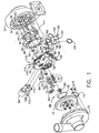
- vanes 36 are mounted to a nozzle wall 38 machined into the turbine housing using posts 40 extending from the vanes for rotational engagement within holes 42 in the nozzle wall.
- Actuation tabs 44 extend from the vanes to be engaged by slots 46 in unison ring 48 which acts as the second nozzle wall. The configuration of the tabs, slots and unison ring will be explained in greater detail subsequently.
- An actuator crank 50 terminates at a first end in a lever arm 52 carrying a pin 54 to engage elliptical slot 56 in the unison ring for rotation of the ring as will be later explained.
- the crank extends into a boss 58 in the center housing casting through a bushing 60 and a gear 62 which is secured to the crank by a pin 64 and is received into an end bearing 66 which mates with aperture 68 in the crank boss.
- An O-ring 70 seals the end bearing and a snap ring 72 secures the end bearing into the aperture 68.
- a bearing system having two journal bearings 74 and a bearing spacer 76 support the shaft wheel assembly in the center housing center bore 78.
- the shaft further extends through a thrust collar 80 which engages a thrust bearing 82 carried between the center housing and compressor back plate.
- a piston ring 84 seals the thrust collar with the shaft bore in the back plate.
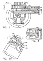
- the integrated actuator for the turbocharger is housed in an actuator boss 82 in the casting of the center housing 18.
- a solenoid valve 84 is mounted in an aperture at one end of the boss while the actuating components are mounted in a second aperture at the opposite end of the boss.
- the actuating components include a piston 86 that incorporates a rod 88 having a rack gear 90 engaging the gear 62 mounted on the crank shaft 50.
- a ring seal 92 surrounds the piston circumference sealing the piston in the bore of the actuator boss. Additional ring seals 94 and 96 seal the piston rod to a rod bore of smaller diameter than the piston bore. The piston bore is sealed with a piston end 98 held in the bore with a snap ring 100.
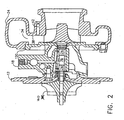
- Fig. 2 is a side sectional elevation of the turbocharger showing the assembled turbine housing, center housing and compressor back plate with the turbine shaft wheel assembly and compressor impeller supported by the bearing assembly.
- Fig. 3 is an end sectional view through the actuator boss and assembled actuator components.
- Fig. 4 shows the alternative freeze plug arrangement for sealing the piston bore.
- nozzle vanes36 in the turbine inlet nozzle are operated by the unison ring 48.
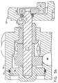
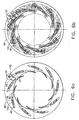
- Fig. 6a shows the unison ring engaged by the end pin 54 of the crank shaft 50 in a radial slot 130. Rotation of the crank shaft causes the offset end pin to traverse the radial slot resulting in rotation of the unison ring.
- the vanes, mounted for rotation on pins 40 which extend into receiving holes 42 in the nozzle wall of the turbine housing, have guide tabs 132 which are received in the slots 46 in the unison ring.
- Fig. 6b shows in phantom the fully open, neutral and fully closed positions of the vanes with tab positioning in the slots.
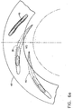
- Fig. 6c is an enlarged view of the unison ring slot with the tab shown in multiple positions.
- the tab incorporates substantially, flat sides 134 and 136 which provide extended engagement of the slot wall by the tab to reduce point wear on the tab.
- the profile of the slot is predetermined to provide maximum engagement with the tab, while engaging first side 134 of the tab at the open and closed end points with maximum area and the second side 136 during the intermediate positioning of the vanes.
- Fig. 6d shows the fully open and fully closed positions of the vanes. A 22 degree rotation of the vanes is provided.
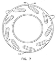
- Fig. 7 shows one embodiment of the unison ring 48 that incorporates blind slots 46 while providing a blind relief 138 on the reverse side of the ring with pressure ports 140 machined into the relief.
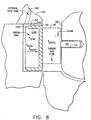
- Fig. 8 is a detail side section of the relieved unison ring engaging the vanes in the nozzle.
- pressure of the exhaust gas entering the nozzle pressurizes the relieved back portion 138 of the unison ring through gap 142 provided by tolerancing of the mounting channel 144 in the back plate 120, through ports 140.
- a feed hole 146 is provided through the back plate into the unison ring mounting channel proximate the location of the ports 144.
- Total pressure of the exhaust gas urges the unison ring against the vanes, which are in turn urged against the nozzle surface 38 in the turbine housing.
- Holes 42 receiving the vane pins 40 are provided with sufficient depth to allow the vanes to be maintained in close contact with the nozzle surface and unison ring for minimum vane leakage.
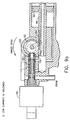
- Figs. 9a through 9e show the various states of the actuation piston 86 and its piston rod 88 driving gear 62 through rack 90.
- the solenoid valve is reacted by a spring 150 having a cap 152 engaging a cam 154 machined into the gear body.
- Various ports, as will be described are then opened and closed, hydraulically positioning the piston which, through the mechanical closed loop of the rack and gear provides positive control on the position of the crank shaft and, therefore, the unison ring.
- the solenoid valve is a proportional servo 4-way hydraulic actuator control valve.
- Fig. 9a if no current is applied to the solenoid, port A is open, port B (top of the piston) is connected to drain port D.
- Fig. 9b when oil pressure is applied from the engine on which the turbocharger is mounted, oil pressure is directed through port A into the bottom of the piston, placing the vanes in a fully open position.
- port A is closed, port A (bottom of the piston) is connected to drain, port B opens and oil pressure is directed to the top of the piston, moving the piston to the left starting to close the vanes.
- Fig. 9c shows the condition of the actuation systems with a balanced state low current in the solenoid.
- Port A is closed, port B is closed and the vanes are positioned as a function of the applied current.
- Fig. 9d shows that port B is opened directing oil pressure to the top of the piston.
- Port A is connected to the drain and the piston moves to the left, moving the vanes in the closed direction.
- the system stabilizes in a balanced state with high current as shown in Fig. 5e with port A closed, port B closed and the vanes positioned as a function of the applied current.
Landscapes
- Engineering & Computer Science (AREA)
- Mechanical Engineering (AREA)
- General Engineering & Computer Science (AREA)
- Chemical & Material Sciences (AREA)
- Combustion & Propulsion (AREA)
- Supercharger (AREA)
- Control Of Turbines (AREA)
- Preparation Of Compounds By Using Micro-Organisms (AREA)
Claims (6)
- Turbocompresseur à géométrie variable comprenant :un carter de turbine '(24) comprenant une entrée (32) pour les gaz d'échappement et une sortie, une volute connectée à l'entrée et une paroi extérieure de buse intégrale (38) adjacente à la volute ;un carter central (18) fixé au carter de turbine et comportant un alésage central (68) portant un ensemble de palier ;un carter de compresseur (10) comprenant une entrée d'air et une sortie d'air comprimé, le carter de compresseur (10) étant fixé au carter central (18) ;une roue de turbine (30) portée dans le carter de turbine (24) et fixée à un arbre (30) s'étendant à travers le carter central (18) et porté par l'ensemble de palier, l'arbre étant fixé à l'extrémité distale de la roue de turbine (30) à une roue à aubes (160) portée dans le carter de compresseur (10) ;une pluralité d'ailettes (36) comprenant des axes de rotation (40) s'étendant à partir d'une première surface substantiellement parallèle à la paroi extérieure de buse, les axes étant accueillis dans des ouvertures espacées sur la circonférence (42) dans la paroi extérieure de buse, les ailettes comprenant en outre des pattes d'actionnement (44) s'étendant à partir d'une deuxième surface des ailettes distale de la première surface ;une bague d'union (48) en position intermédiaire entre le carter central et les ailettes, la bague d'union comportant une pluralité d'encoches (46) égales en nombre aux ailettes, lesdites encoches orientées obliquement par rapport à une circonférence de la bague d'union et accueillant les pattes, la bague d'union comportant en outre une encoche radiale (56) ;un arbre de manivelle (50) comprenant un axe (54) engagé dans l'encoche radiale, l'arbre de manivelle se déplaçant continuellement d'une première position à une deuxième position, le mouvement de l'arbre de manivelle (50) conduisant l'axe (54) à se déplacer dans l'encoche radiale (56) et à appliquer une force perpendiculaire à l'encoche radiale pour produire un mouvement rotatif de la bague d'union (48), le mouvement rotatif de la bague d'union conduisant les pattes (44) à traverser les encoches d'actionnement (46) d'une première extrémité des encoches à une deuxième extrémité des encoches ; etun moyen pour déplacer l'arbre de manivelle de la première position à la deuxième position, caractérisé en ce que les pattes comportent des côtés substantiellement plats qui sont accueillis dans les encoches d'actionnement, les encoches étant configurées pour fournir un engagement étendu entre les côtés substantiellement plats et les surfaces intérieures des encoches (46).
- Turbocompresseur à géométrie variable selon la revendication 1, dans lequel les encoches d'actionnement comportent un profil prédéterminé pour fournir l'engagement maximum d'un premier côté (134) de chaque patte avec la patte située à la première extrémité et à la deuxième extrémité de l'encoche et un engagement maximum d'un deuxième côté (136) de chaque patte avec la patte située dans l'encoche en position intermédiaire entre la première et la deuxième extrémités.
- Turbocompresseur à géométrie variable selon la revendication 1, dans lequel le moyen de déplacement comprend un actionneur hydraulique intégral au carter central et comprenant :un piston (86) accueilli dans un bossage (85) coulé intégralement dans le carter central (18) pour produire le mouvement alternatif perpendiculaire à l'arbre de manivelle (50) ;une tige de piston (88) fixée au piston à une première extrémité ;un moyen pour fixer la tige de piston (88) à l'arbre de manivelle (50), le moyen de fixation convertissant le mouvement alternatif de la tige de piston en mouvement rotatif de l'arbre ; etun moyen pour faire varier de façon contrôlée la pression hydraulique sur les côtés opposés du piston pour produire un mouvement d'une première position correspondant à la première position de l'arbre de manivelle (50) à une deuxième position correspondant à la deuxième position de l'arbre de manivelle (50).
- Turbocompresseur à géométrie variable selon la revendication 3, dans lequel le moyen de fixation comprend :une crémaillère d'engrenage (90) sur la tige de piston (88) etun pignon d'engrenage sur l'arbre de manivelle (50).
- Turbocompresseur à géométrie variable selon la revendication 3, dans lequel le moyen servant à faire varier de façon contrôlée la pression hydraulique comprend :une queue de soupape hydraulique comportant des orifices multiples et pouvant être déplacée par un solénoïde à courant électrique variable (84) équilibré par un ressort de rappel (150) ;une source de pression hydraulique en communication avec un premier orifice quand la queue de soupape est à une première position et avec un deuxième orifice quand la queue de soupape est à une deuxième position ;un drain hydraulique en communication avec un troisième orifice quand la queue de soupape est à la première position et avec un quatrième orifice quand la queue de soupape est à la deuxième position ;un premier conduit communicant avec un premier côté du piston et communiquant avec le premier orifice quand la queue de soupape est à la première position et avec le quatrième orifice quand la queue de soupape est à la deuxième position ;un deuxième conduit communicant avec un deuxième côté du piston et communiquant avec le troisième orifice quand la queue de soupape est à la première position et avec le deuxième orifice quand la queue de soupape est à la deuxième position ; etune came sur le bras de manivelle s'engageant en fonctionnement avec le ressort de rappel.
- Turbocompresseur à géométrie variable selon la revendication 1, dans lequel les encoches d'actionnement (46) sont aveugles et comprennent en outre :un canal annulaire aménagé dans le carter central accueillant étroitement la bague d'union ; etun moyen pour alimenter la pression d'air au canal pour forcer la bague d'union en contact étroit avec la deuxième surface des ailettes.
Applications Claiming Priority (1)
| Application Number | Priority Date | Filing Date | Title |
|---|---|---|---|
| PCT/US2000/006512 WO2001069045A1 (fr) | 2000-03-13 | 2000-03-13 | Turbocompresseur a geometrie variable |
Publications (2)
| Publication Number | Publication Date |
|---|---|
| EP1264078A1 EP1264078A1 (fr) | 2002-12-11 |
| EP1264078B1 true EP1264078B1 (fr) | 2005-12-14 |
Family
ID=21741144
Family Applications (1)
| Application Number | Title | Priority Date | Filing Date |
|---|---|---|---|
| EP00917890A Expired - Lifetime EP1264078B1 (fr) | 2000-03-13 | 2000-03-13 | Turbocompresseur a geometrie variable |
Country Status (9)
| Country | Link |
|---|---|
| EP (1) | EP1264078B1 (fr) |
| JP (1) | JP4460814B2 (fr) |
| KR (1) | KR100642050B1 (fr) |
| CN (1) | CN1313711C (fr) |
| AT (1) | ATE313007T1 (fr) |
| AU (1) | AU758433B2 (fr) |
| CA (1) | CA2349917C (fr) |
| DE (2) | DE1264078T1 (fr) |
| WO (1) | WO2001069045A1 (fr) |
Cited By (2)
| Publication number | Priority date | Publication date | Assignee | Title |
|---|---|---|---|---|
| US8109090B2 (en) | 2006-10-27 | 2012-02-07 | Komatsu Ltd. | Variable turbo supercharger and method of returning oil from hydraulic drive |
| US8770087B2 (en) | 2008-03-21 | 2014-07-08 | Komatsu Ltd. | Hydraulic servo-drive device and variable turbo-supercharger using the same |
Families Citing this family (29)
| Publication number | Priority date | Publication date | Assignee | Title |
|---|---|---|---|---|
| DE10237413B4 (de) * | 2002-08-16 | 2004-07-15 | Daimlerchrysler Ag | Abgasturbolader für eine Brennkraftmaschine |
| DE10253693B4 (de) * | 2002-11-18 | 2005-12-01 | Borgwarner Turbo Systems Gmbh | Abgasturbolader |
| US6895751B1 (en) * | 2004-03-08 | 2005-05-24 | Christopher Greentree | Vane control |
| DE102004023214A1 (de) * | 2004-05-11 | 2005-12-08 | Volkswagen Ag | Abgasturbolader für eine Brennkraftmaschine mit variabler Turbinengeometrie |
| JP4483571B2 (ja) | 2004-12-24 | 2010-06-16 | トヨタ自動車株式会社 | 可変容量型ターボチャージャー |
| JP4560468B2 (ja) * | 2005-10-04 | 2010-10-13 | 株式会社小松製作所 | 可変ターボ過給機およびこれを備えたエンジン |
| US7958730B2 (en) | 2005-12-30 | 2011-06-14 | Honeywell International Inc. | Control of dual stage turbocharging |
| KR101258687B1 (ko) * | 2006-03-14 | 2013-04-26 | 보르그워너 인코퍼레이티드 | 터보차저 |
| US7559199B2 (en) * | 2006-09-22 | 2009-07-14 | Honeywell International Inc. | Variable-nozzle cartridge for a turbocharger |
| GB2455950B (en) | 2006-09-29 | 2011-06-01 | Komatsu Mfg Co Ltd | Variable turbo supercharger and method of driving the same |
| JP4641521B2 (ja) | 2006-09-29 | 2011-03-02 | 株式会社小松製作所 | 可変ターボ過給機およびその駆動方法 |
| JP4780666B2 (ja) * | 2006-11-29 | 2011-09-28 | 株式会社小松製作所 | シルティング防止制御装置および方法 |
| JP4820765B2 (ja) * | 2007-01-31 | 2011-11-24 | 株式会社小松製作所 | 可変ターボ過給機 |
| JP2009299767A (ja) * | 2008-06-12 | 2009-12-24 | Komatsu Ltd | 油圧サーボ駆動装置 |
| DE112009004309T5 (de) * | 2008-12-11 | 2012-05-24 | Borgwarner Inc. | Vereinfachter Turbolader mit veränderlicher Geometrie und veränderlicher Dose |
| CN101539034B (zh) * | 2009-04-16 | 2010-12-08 | 上海交通大学 | 周向弯角可调式静叶机构 |
| CN101634233B (zh) * | 2009-08-20 | 2011-07-20 | 康跃科技股份有限公司 | 可变几何涡轮增压器的气动喷嘴 |
| DE102009057664A1 (de) * | 2009-12-09 | 2011-06-16 | Ihi Charging Systems International Gmbh | Verstelleinrichtung für eine Aufladeeinrichtung, insbesondere für einen Abgasturbolader |
| US20120023936A1 (en) * | 2010-07-30 | 2012-02-02 | Caterpillar Inc. | Nozzled turbocharger turbine |
| US8992165B2 (en) * | 2010-09-22 | 2015-03-31 | Cummins Turbo Technologies Limited | Variable geometry turbine |
| CN102297016B (zh) * | 2011-08-15 | 2012-12-12 | 无锡凯迪增压器配件有限公司 | 双叶片喷嘴系统的涡轮增压器 |
| KR20140063474A (ko) | 2012-11-16 | 2014-05-27 | 에이비비 터보 시스템즈 아게 | 노즐 링 |
| US9429033B2 (en) * | 2013-11-08 | 2016-08-30 | Honeywell International Inc. | Drive arrangement for a unison ring of a variable-vane assembly |
| JP2017527739A (ja) * | 2014-09-23 | 2017-09-21 | ボーグワーナー インコーポレーテッド | 一体型アクチュエータを備えるターボチャージャ |
| US10018107B2 (en) * | 2015-07-10 | 2018-07-10 | Kangyue Technology Co., Ltd | Balanced vanes and integrated actuation system for a variable geometry turbocharger |
| IL241683B (en) | 2015-09-17 | 2020-09-30 | Israel Aerospace Ind Ltd | Multi-serial charger |
| CN110608091A (zh) * | 2018-06-14 | 2019-12-24 | 博格华纳公司 | 用于具有可变调节机构的压缩机的装置 |
| CN115744828B (zh) * | 2022-11-22 | 2023-08-04 | 福建德尔科技股份有限公司 | 一种电子级三氟化氯生产用的增压器 |
| CN118565225B (zh) * | 2024-07-30 | 2024-10-01 | 山西绿源碳索科技有限公司 | 一种节能加热炉的烟气余热回收系统及方法 |
Family Cites Families (8)
| Publication number | Priority date | Publication date | Assignee | Title |
|---|---|---|---|---|
| GB731822A (en) * | 1952-03-14 | 1955-06-15 | Power Jets Res & Dev Ltd | Improvements relating to turbines or compressors for operation with gaseous fluids |
| US4274329A (en) * | 1978-11-13 | 1981-06-23 | Weyer Paul P | Rotary actuator apparatus |
| US4300869A (en) * | 1980-02-11 | 1981-11-17 | Swearingen Judson S | Method and apparatus for controlling clamping forces in fluid flow control assemblies |
| US4502836A (en) * | 1982-07-02 | 1985-03-05 | Swearingen Judson S | Method for nozzle clamping force control |
| US4654941A (en) * | 1984-04-20 | 1987-04-07 | The Garrett Corporation | Method of assembling a variable nozzle turbocharger |
| US4726744A (en) * | 1985-10-24 | 1988-02-23 | Household Manufacturing, Inc. | Tubocharger with variable vane |
| US4804316A (en) | 1985-12-11 | 1989-02-14 | Allied-Signal Inc. | Suspension for the pivoting vane actuation mechanism of a variable nozzle turbocharger |
| US4679984A (en) | 1985-12-11 | 1987-07-14 | The Garrett Corporation | Actuation system for variable nozzle turbine |
-
2000
- 2000-03-13 EP EP00917890A patent/EP1264078B1/fr not_active Expired - Lifetime
- 2000-03-13 CA CA002349917A patent/CA2349917C/fr not_active Expired - Fee Related
- 2000-03-13 AU AU38796/00A patent/AU758433B2/en not_active Ceased
- 2000-03-13 DE DE1264078T patent/DE1264078T1/de active Pending
- 2000-03-13 KR KR1020017004407A patent/KR100642050B1/ko not_active Expired - Lifetime
- 2000-03-13 WO PCT/US2000/006512 patent/WO2001069045A1/fr not_active Ceased
- 2000-03-13 DE DE60024879T patent/DE60024879T2/de not_active Expired - Lifetime
- 2000-03-13 CN CNB008193304A patent/CN1313711C/zh not_active Expired - Lifetime
- 2000-03-13 JP JP2001567905A patent/JP4460814B2/ja not_active Expired - Lifetime
- 2000-03-13 AT AT00917890T patent/ATE313007T1/de not_active IP Right Cessation
Cited By (2)
| Publication number | Priority date | Publication date | Assignee | Title |
|---|---|---|---|---|
| US8109090B2 (en) | 2006-10-27 | 2012-02-07 | Komatsu Ltd. | Variable turbo supercharger and method of returning oil from hydraulic drive |
| US8770087B2 (en) | 2008-03-21 | 2014-07-08 | Komatsu Ltd. | Hydraulic servo-drive device and variable turbo-supercharger using the same |
Also Published As
| Publication number | Publication date |
|---|---|
| JP2003527522A (ja) | 2003-09-16 |
| CN1313711C (zh) | 2007-05-02 |
| CA2349917A1 (fr) | 2001-09-13 |
| AU758433B2 (en) | 2003-03-20 |
| WO2001069045A1 (fr) | 2001-09-20 |
| CN1451076A (zh) | 2003-10-22 |
| DE1264078T1 (de) | 2003-06-26 |
| DE60024879D1 (de) | 2006-01-19 |
| EP1264078A1 (fr) | 2002-12-11 |
| AU3879600A (en) | 2001-09-24 |
| CA2349917C (fr) | 2008-12-02 |
| DE60024879T2 (de) | 2006-07-20 |
| JP4460814B2 (ja) | 2010-05-12 |
| KR20020081047A (ko) | 2002-10-26 |
| KR100642050B1 (ko) | 2006-11-10 |
| ATE313007T1 (de) | 2005-12-15 |
Similar Documents
| Publication | Publication Date | Title |
|---|---|---|
| EP1264078B1 (fr) | Turbocompresseur a geometrie variable | |
| US6269642B1 (en) | Variable geometry turbocharger | |
| US8172516B2 (en) | Variable geometry turbine | |
| EP2044294B1 (fr) | Turbocompresseur à double soupape de décharge | |
| KR101131988B1 (ko) | 가변형상터빈 | |
| US8105020B2 (en) | Turbocharger | |
| CN1454285A (zh) | 带有滑动活塞的可变形状涡轮增压器 | |
| US9951653B2 (en) | Variable geometry turbomachine | |
| JP4991765B2 (ja) | 調整可能なガイド装置 | |
| EP1411281B1 (fr) | Vanne à papillon | |
| WO1989011583A1 (fr) | Dispositif a suralimentation | |
| US8821112B2 (en) | Variable geometry turbine | |
| EP3797214B1 (fr) | Mécanisme simplifié pour actionneur excentrique scotch | |
| CN107849936A (zh) | 可变几何涡轮增压器的平衡叶片和整体式致动系统 | |
| CN101223337B (zh) | 几何构造可变涡轮 | |
| RU2011850C1 (ru) | Турбонагнетатель | |
| GB2575979A (en) | Valve assembly | |
| WO2024157030A1 (fr) | Turbine à géométrie variable |
Legal Events
| Date | Code | Title | Description |
|---|---|---|---|
| PUAI | Public reference made under article 153(3) epc to a published international application that has entered the european phase |
Free format text: ORIGINAL CODE: 0009012 |
|
| 17P | Request for examination filed |
Effective date: 20010403 |
|
| AK | Designated contracting states |
Kind code of ref document: A1 Designated state(s): AT BE CH CY DE DK ES FI FR GB GR IE IT LI LU MC NL PT SE |
|
| AX | Request for extension of the european patent |
Free format text: AL;LT;LV;MK;RO;SI |
|
| EL | Fr: translation of claims filed | ||
| DET | De: translation of patent claims | ||
| 17Q | First examination report despatched |
Effective date: 20040506 |
|
| GRAP | Despatch of communication of intention to grant a patent |
Free format text: ORIGINAL CODE: EPIDOSNIGR1 |
|
| GRAS | Grant fee paid |
Free format text: ORIGINAL CODE: EPIDOSNIGR3 |
|
| GRAA | (expected) grant |
Free format text: ORIGINAL CODE: 0009210 |
|
| AK | Designated contracting states |
Kind code of ref document: B1 Designated state(s): AT BE CH CY DE DK ES FI FR GB GR IE IT LI LU MC NL PT SE |
|
| PG25 | Lapsed in a contracting state [announced via postgrant information from national office to epo] |
Ref country code: FI Free format text: LAPSE BECAUSE OF FAILURE TO SUBMIT A TRANSLATION OF THE DESCRIPTION OR TO PAY THE FEE WITHIN THE PRESCRIBED TIME-LIMIT Effective date: 20051214 Ref country code: IT Free format text: LAPSE BECAUSE OF FAILURE TO SUBMIT A TRANSLATION OF THE DESCRIPTION OR TO PAY THE FEE WITHIN THE PRESCRIBED TIME-LIMIT;WARNING: LAPSES OF ITALIAN PATENTS WITH EFFECTIVE DATE BEFORE 2007 MAY HAVE OCCURRED AT ANY TIME BEFORE 2007. THE CORRECT EFFECTIVE DATE MAY BE DIFFERENT FROM THE ONE RECORDED. Effective date: 20051214 Ref country code: AT Free format text: LAPSE BECAUSE OF FAILURE TO SUBMIT A TRANSLATION OF THE DESCRIPTION OR TO PAY THE FEE WITHIN THE PRESCRIBED TIME-LIMIT Effective date: 20051214 Ref country code: LI Free format text: LAPSE BECAUSE OF FAILURE TO SUBMIT A TRANSLATION OF THE DESCRIPTION OR TO PAY THE FEE WITHIN THE PRESCRIBED TIME-LIMIT Effective date: 20051214 Ref country code: NL Free format text: LAPSE BECAUSE OF FAILURE TO SUBMIT A TRANSLATION OF THE DESCRIPTION OR TO PAY THE FEE WITHIN THE PRESCRIBED TIME-LIMIT Effective date: 20051214 Ref country code: BE Free format text: LAPSE BECAUSE OF FAILURE TO SUBMIT A TRANSLATION OF THE DESCRIPTION OR TO PAY THE FEE WITHIN THE PRESCRIBED TIME-LIMIT Effective date: 20051214 Ref country code: CH Free format text: LAPSE BECAUSE OF FAILURE TO SUBMIT A TRANSLATION OF THE DESCRIPTION OR TO PAY THE FEE WITHIN THE PRESCRIBED TIME-LIMIT Effective date: 20051214 |
|
| REG | Reference to a national code |
Ref country code: GB Ref legal event code: FG4D |
|
| REG | Reference to a national code |
Ref country code: CH Ref legal event code: EP |
|
| REG | Reference to a national code |
Ref country code: IE Ref legal event code: FG4D |
|
| REF | Corresponds to: |
Ref document number: 60024879 Country of ref document: DE Date of ref document: 20060119 Kind code of ref document: P |
|
| PG25 | Lapsed in a contracting state [announced via postgrant information from national office to epo] |
Ref country code: IE Free format text: LAPSE BECAUSE OF NON-PAYMENT OF DUE FEES Effective date: 20060313 |
|
| PG25 | Lapsed in a contracting state [announced via postgrant information from national office to epo] |
Ref country code: DK Free format text: LAPSE BECAUSE OF FAILURE TO SUBMIT A TRANSLATION OF THE DESCRIPTION OR TO PAY THE FEE WITHIN THE PRESCRIBED TIME-LIMIT Effective date: 20060314 Ref country code: SE Free format text: LAPSE BECAUSE OF FAILURE TO SUBMIT A TRANSLATION OF THE DESCRIPTION OR TO PAY THE FEE WITHIN THE PRESCRIBED TIME-LIMIT Effective date: 20060314 Ref country code: GR Free format text: LAPSE BECAUSE OF FAILURE TO SUBMIT A TRANSLATION OF THE DESCRIPTION OR TO PAY THE FEE WITHIN THE PRESCRIBED TIME-LIMIT Effective date: 20060314 |
|
| PG25 | Lapsed in a contracting state [announced via postgrant information from national office to epo] |
Ref country code: ES Free format text: LAPSE BECAUSE OF FAILURE TO SUBMIT A TRANSLATION OF THE DESCRIPTION OR TO PAY THE FEE WITHIN THE PRESCRIBED TIME-LIMIT Effective date: 20060325 |
|
| PG25 | Lapsed in a contracting state [announced via postgrant information from national office to epo] |
Ref country code: MC Free format text: LAPSE BECAUSE OF NON-PAYMENT OF DUE FEES Effective date: 20060331 Ref country code: LU Free format text: LAPSE BECAUSE OF NON-PAYMENT OF DUE FEES Effective date: 20060331 |
|
| PG25 | Lapsed in a contracting state [announced via postgrant information from national office to epo] |
Ref country code: PT Free format text: LAPSE BECAUSE OF FAILURE TO SUBMIT A TRANSLATION OF THE DESCRIPTION OR TO PAY THE FEE WITHIN THE PRESCRIBED TIME-LIMIT Effective date: 20060515 |
|
| NLV1 | Nl: lapsed or annulled due to failure to fulfill the requirements of art. 29p and 29m of the patents act | ||
| REG | Reference to a national code |
Ref country code: CH Ref legal event code: PL |
|
| ET | Fr: translation filed | ||
| PLBE | No opposition filed within time limit |
Free format text: ORIGINAL CODE: 0009261 |
|
| STAA | Information on the status of an ep patent application or granted ep patent |
Free format text: STATUS: NO OPPOSITION FILED WITHIN TIME LIMIT |
|
| 26N | No opposition filed |
Effective date: 20060915 |
|
| REG | Reference to a national code |
Ref country code: IE Ref legal event code: MM4A |
|
| PG25 | Lapsed in a contracting state [announced via postgrant information from national office to epo] |
Ref country code: CY Free format text: LAPSE BECAUSE OF FAILURE TO SUBMIT A TRANSLATION OF THE DESCRIPTION OR TO PAY THE FEE WITHIN THE PRESCRIBED TIME-LIMIT Effective date: 20051214 |
|
| REG | Reference to a national code |
Ref country code: FR Ref legal event code: PLFP Year of fee payment: 17 |
|
| REG | Reference to a national code |
Ref country code: FR Ref legal event code: PLFP Year of fee payment: 18 |
|
| REG | Reference to a national code |
Ref country code: FR Ref legal event code: PLFP Year of fee payment: 19 |
|
| PGFP | Annual fee paid to national office [announced via postgrant information from national office to epo] |
Ref country code: GB Payment date: 20190327 Year of fee payment: 20 Ref country code: FR Payment date: 20190328 Year of fee payment: 20 |
|
| PGFP | Annual fee paid to national office [announced via postgrant information from national office to epo] |
Ref country code: DE Payment date: 20190411 Year of fee payment: 20 |
|
| REG | Reference to a national code |
Ref country code: DE Ref legal event code: R071 Ref document number: 60024879 Country of ref document: DE |
|
| REG | Reference to a national code |
Ref country code: GB Ref legal event code: PE20 Expiry date: 20200312 |
|
| PG25 | Lapsed in a contracting state [announced via postgrant information from national office to epo] |
Ref country code: GB Free format text: LAPSE BECAUSE OF EXPIRATION OF PROTECTION Effective date: 20200312 |