EP1264086B1 - Verfahren und einrichtung zur kühlung einer brennkraftmaschine eines kraftfahrzeugs - Google Patents
Verfahren und einrichtung zur kühlung einer brennkraftmaschine eines kraftfahrzeugsInfo
- Publication number
- EP1264086B1 EP1264086B1 EP01907697A EP01907697A EP1264086B1 EP 1264086 B1 EP1264086 B1 EP 1264086B1 EP 01907697 A EP01907697 A EP 01907697A EP 01907697 A EP01907697 A EP 01907697A EP 1264086 B1 EP1264086 B1 EP 1264086B1
- Authority
- EP
- European Patent Office
- Prior art keywords
- temperature
- engine
- coolant
- branch
- vehicle
- Prior art date
- Legal status (The legal status is an assumption and is not a legal conclusion. Google has not performed a legal analysis and makes no representation as to the accuracy of the status listed.)
- Expired - Lifetime
Links
- 238000001816 cooling Methods 0.000 title claims description 20
- 238000000034 method Methods 0.000 title claims description 8
- 239000002826 coolant Substances 0.000 claims description 58
- 239000012530 fluid Substances 0.000 claims description 32
- 238000009423 ventilation Methods 0.000 claims description 26
- 230000001105 regulatory effect Effects 0.000 claims description 10
- 239000007788 liquid Substances 0.000 claims description 8
- 230000001276 controlling effect Effects 0.000 claims description 5
- 239000013529 heat transfer fluid Substances 0.000 claims description 5
- 230000006870 function Effects 0.000 description 32
- 239000012809 cooling fluid Substances 0.000 description 13
- 230000007423 decrease Effects 0.000 description 5
- 230000008859 change Effects 0.000 description 2
- 239000000110 cooling liquid Substances 0.000 description 2
- 238000010438 heat treatment Methods 0.000 description 2
- 230000000750 progressive effect Effects 0.000 description 2
- XLYOFNOQVPJJNP-UHFFFAOYSA-N water Substances O XLYOFNOQVPJJNP-UHFFFAOYSA-N 0.000 description 2
- 230000003416 augmentation Effects 0.000 description 1
- 230000033228 biological regulation Effects 0.000 description 1
- 230000015556 catabolic process Effects 0.000 description 1
- 238000002485 combustion reaction Methods 0.000 description 1
- 230000000295 complement effect Effects 0.000 description 1
- 230000008878 coupling Effects 0.000 description 1
- 238000010168 coupling process Methods 0.000 description 1
- 238000005859 coupling reaction Methods 0.000 description 1
- 230000003247 decreasing effect Effects 0.000 description 1
- 238000006731 degradation reaction Methods 0.000 description 1
- 239000003344 environmental pollutant Substances 0.000 description 1
- 230000010365 information processing Effects 0.000 description 1
- 239000010687 lubricating oil Substances 0.000 description 1
- 231100000719 pollutant Toxicity 0.000 description 1
- 230000009467 reduction Effects 0.000 description 1
- 238000012163 sequencing technique Methods 0.000 description 1
- 230000000930 thermomechanical effect Effects 0.000 description 1
Images



Classifications
-
- F—MECHANICAL ENGINEERING; LIGHTING; HEATING; WEAPONS; BLASTING
- F01—MACHINES OR ENGINES IN GENERAL; ENGINE PLANTS IN GENERAL; STEAM ENGINES
- F01P—COOLING OF MACHINES OR ENGINES IN GENERAL; COOLING OF INTERNAL-COMBUSTION ENGINES
- F01P7/00—Controlling of coolant flow
- F01P7/14—Controlling of coolant flow the coolant being liquid
- F01P7/16—Controlling of coolant flow the coolant being liquid by thermostatic control
- F01P7/167—Controlling of coolant flow the coolant being liquid by thermostatic control by adjusting the pre-set temperature according to engine parameters, e.g. engine load, engine speed
-
- F—MECHANICAL ENGINEERING; LIGHTING; HEATING; WEAPONS; BLASTING
- F01—MACHINES OR ENGINES IN GENERAL; ENGINE PLANTS IN GENERAL; STEAM ENGINES
- F01P—COOLING OF MACHINES OR ENGINES IN GENERAL; COOLING OF INTERNAL-COMBUSTION ENGINES
- F01P7/00—Controlling of coolant flow
- F01P7/14—Controlling of coolant flow the coolant being liquid
- F01P2007/143—Controlling of coolant flow the coolant being liquid using restrictions
-
- F—MECHANICAL ENGINEERING; LIGHTING; HEATING; WEAPONS; BLASTING
- F01—MACHINES OR ENGINES IN GENERAL; ENGINE PLANTS IN GENERAL; STEAM ENGINES
- F01P—COOLING OF MACHINES OR ENGINES IN GENERAL; COOLING OF INTERNAL-COMBUSTION ENGINES
- F01P7/00—Controlling of coolant flow
- F01P7/14—Controlling of coolant flow the coolant being liquid
- F01P2007/146—Controlling of coolant flow the coolant being liquid using valves
-
- F—MECHANICAL ENGINEERING; LIGHTING; HEATING; WEAPONS; BLASTING
- F01—MACHINES OR ENGINES IN GENERAL; ENGINE PLANTS IN GENERAL; STEAM ENGINES
- F01P—COOLING OF MACHINES OR ENGINES IN GENERAL; COOLING OF INTERNAL-COMBUSTION ENGINES
- F01P2023/00—Signal processing; Details thereof
-
- F—MECHANICAL ENGINEERING; LIGHTING; HEATING; WEAPONS; BLASTING
- F01—MACHINES OR ENGINES IN GENERAL; ENGINE PLANTS IN GENERAL; STEAM ENGINES
- F01P—COOLING OF MACHINES OR ENGINES IN GENERAL; COOLING OF INTERNAL-COMBUSTION ENGINES
- F01P2025/00—Measuring
- F01P2025/08—Temperature
-
- F—MECHANICAL ENGINEERING; LIGHTING; HEATING; WEAPONS; BLASTING
- F01—MACHINES OR ENGINES IN GENERAL; ENGINE PLANTS IN GENERAL; STEAM ENGINES
- F01P—COOLING OF MACHINES OR ENGINES IN GENERAL; COOLING OF INTERNAL-COMBUSTION ENGINES
- F01P2025/00—Measuring
- F01P2025/08—Temperature
- F01P2025/13—Ambient temperature
-
- F—MECHANICAL ENGINEERING; LIGHTING; HEATING; WEAPONS; BLASTING
- F01—MACHINES OR ENGINES IN GENERAL; ENGINE PLANTS IN GENERAL; STEAM ENGINES
- F01P—COOLING OF MACHINES OR ENGINES IN GENERAL; COOLING OF INTERNAL-COMBUSTION ENGINES
- F01P2025/00—Measuring
- F01P2025/60—Operating parameters
-
- F—MECHANICAL ENGINEERING; LIGHTING; HEATING; WEAPONS; BLASTING
- F01—MACHINES OR ENGINES IN GENERAL; ENGINE PLANTS IN GENERAL; STEAM ENGINES
- F01P—COOLING OF MACHINES OR ENGINES IN GENERAL; COOLING OF INTERNAL-COMBUSTION ENGINES
- F01P2025/00—Measuring
- F01P2025/60—Operating parameters
- F01P2025/62—Load
-
- F—MECHANICAL ENGINEERING; LIGHTING; HEATING; WEAPONS; BLASTING
- F01—MACHINES OR ENGINES IN GENERAL; ENGINE PLANTS IN GENERAL; STEAM ENGINES
- F01P—COOLING OF MACHINES OR ENGINES IN GENERAL; COOLING OF INTERNAL-COMBUSTION ENGINES
- F01P2025/00—Measuring
- F01P2025/60—Operating parameters
- F01P2025/64—Number of revolutions
-
- F—MECHANICAL ENGINEERING; LIGHTING; HEATING; WEAPONS; BLASTING
- F01—MACHINES OR ENGINES IN GENERAL; ENGINE PLANTS IN GENERAL; STEAM ENGINES
- F01P—COOLING OF MACHINES OR ENGINES IN GENERAL; COOLING OF INTERNAL-COMBUSTION ENGINES
- F01P2025/00—Measuring
- F01P2025/60—Operating parameters
- F01P2025/66—Vehicle speed
-
- F—MECHANICAL ENGINEERING; LIGHTING; HEATING; WEAPONS; BLASTING
- F01—MACHINES OR ENGINES IN GENERAL; ENGINE PLANTS IN GENERAL; STEAM ENGINES
- F01P—COOLING OF MACHINES OR ENGINES IN GENERAL; COOLING OF INTERNAL-COMBUSTION ENGINES
- F01P2060/00—Cooling circuits using auxiliaries
- F01P2060/02—Intercooler
-
- F—MECHANICAL ENGINEERING; LIGHTING; HEATING; WEAPONS; BLASTING
- F01—MACHINES OR ENGINES IN GENERAL; ENGINE PLANTS IN GENERAL; STEAM ENGINES
- F01P—COOLING OF MACHINES OR ENGINES IN GENERAL; COOLING OF INTERNAL-COMBUSTION ENGINES
- F01P2060/00—Cooling circuits using auxiliaries
- F01P2060/04—Lubricant cooler
-
- F—MECHANICAL ENGINEERING; LIGHTING; HEATING; WEAPONS; BLASTING
- F01—MACHINES OR ENGINES IN GENERAL; ENGINE PLANTS IN GENERAL; STEAM ENGINES
- F01P—COOLING OF MACHINES OR ENGINES IN GENERAL; COOLING OF INTERNAL-COMBUSTION ENGINES
- F01P7/00—Controlling of coolant flow
- F01P7/02—Controlling of coolant flow the coolant being cooling-air
- F01P7/04—Controlling of coolant flow the coolant being cooling-air by varying pump speed, e.g. by changing pump-drive gear ratio
- F01P7/048—Controlling of coolant flow the coolant being cooling-air by varying pump speed, e.g. by changing pump-drive gear ratio using electrical drives
-
- F—MECHANICAL ENGINEERING; LIGHTING; HEATING; WEAPONS; BLASTING
- F01—MACHINES OR ENGINES IN GENERAL; ENGINE PLANTS IN GENERAL; STEAM ENGINES
- F01P—COOLING OF MACHINES OR ENGINES IN GENERAL; COOLING OF INTERNAL-COMBUSTION ENGINES
- F01P7/00—Controlling of coolant flow
- F01P7/14—Controlling of coolant flow the coolant being liquid
- F01P7/16—Controlling of coolant flow the coolant being liquid by thermostatic control
- F01P7/164—Controlling of coolant flow the coolant being liquid by thermostatic control by varying pump speed
Definitions
- the invention relates to a method and a cooling device of a motor vehicle engine.
- the invention more particularly relates to a cooling device comprising a hydraulic coolant coolant circuit, associated with a circulation pump thereof through the vehicle engine and different branches of the circuit.
- Thermal equipment of the vehicle can be arranged in the different branches of the circuit.
- the cooling systems are designed to ensure that the motors withstand the thermomechanical stresses resulting from combustion.
- complementary functions are implemented in addition to the main cooling of the engine, to improve the overall efficiency or to offer and guarantee services to vehicle users, such as, for example, the heating of the passenger compartment.
- the cooling systems are dimensioned from the operating points at maximum speed and full load of the engine and are therefore oversized in most cases of use of vehicles.
- the operating parameters of the engine are not optimized, which results in a degradation of the performance of the latter, such as increased consumption, a high level of pollutant emission and a reduction in the thermal and acoustic comfort of the engine. vehicle.
- FR-A- 2,456,838 discloses a method and a cooling device of a motor vehicle engine, of the type comprising a hydraulic fluid coolant circuit, associated with a pump 2 for circulation thereof through the engine of the vehicle and different branches of the circuit, in which thermal equipment of the vehicle is arranged, at least some of the branches of the circuit being provided with electronically controlled actuators for regulating the circulation of the fluid therein, the device comprising acquisition means information relating to the operating conditions of the vehicle, connected to means for electronically controlling the operation of the actuators, for regulating the volume and the flow rate of fluid circulating in the hydraulic circuit in order to optimize the operation of the engine, the circuit comprising a branch 8 provided with an actuator 6 controlled and provided with means 3 forming a radiator, the means of ac quisition of information being able to determine the temperature of the cooling fluid, so that when the temperature of the fluid is greater than a threshold temperature of 95 ° C determined from which the engine is said "hot", the means of control regulate the flow rate in the radiator branch so as to maintain the temperature of
- the document EP557113 describes a cooling system of an engine comprising, a heat transfer fluid loop connected to a radiator, and means for regulating the flow of the liquid in this loop.
- the flow control means are slaved to the operating conditions of the vehicle, in particular by means of sensors the temperature of the liquid located in different parts of the loop.
- the flow of the coolant in the radiator loop is controlled in particular to regulate the temperatures of the liquid at the outlet and at the inlet of the engine around respective set values.
- this system has a complex structure and uses a large number of measured state variables, without optimizing heat exchanges with the coolant.
- An object of the present invention is to provide a method of cooling a motor vehicle engine, overcoming all or part of the disadvantages of the prior art noted above.
- a method of cooling a motor vehicle engine consisting in regulating the volume and the flow rate of a coolant in a hydraulic circuit (2) provided with a branch (4) provided with an actuator (14) electronically controlled and provided with means (9) forming a radiator, the method comprising a first step of determining the temperature (T) of the cooling fluid, a step of comparing this temperature with a threshold temperature (T2) determined from which the motor (1) is said to be "hot", and, when the temperature (T) of the fluid is greater than the threshold temperature (T2), the flow rate in the radiator branch (4) is regulated in such a way that to maintain the temperature (T) of the coolant around a set value (Tc) determined, the curve representative of the opening (0) of the thermostatic valve (4) as a function of the temperature (T) of the fluid of remindssem ent having a hysteresis (h1, h2) around the set temperature (Tc1, Tc2), so as to regulate the temperature (T) of the coolant at said
- Another object of the present invention is to provide a cooling device of a motor vehicle engine, overcoming all or part of the disadvantages of the prior art noted above.
- a cooling device of a motor vehicle engine of the type comprising a hydraulic circuit (2) of coolant, associated with a pump (3) for circulating it through the engine (1).
- a hydraulic circuit (2) of coolant associated with a pump (3) for circulating it through the engine (1).
- thermal equipment (9, 10, 11, 12, 13, 140, 150, 160) of the vehicle are arranged, less some of the branches (4, 5, 6, 7, 8, 44) of the circuit (2) being provided with electronically controlled actuators (14, 15, 16, 17, 18, 29) for regulating the circulation of the fluid in those
- the device comprising means (22) for acquiring information relating to the operating conditions of the vehicle, connected to means (19) for controlling the operation of the actuators (14, 15, 16, 17, 18, 29 ), to regulate the volume and the flow rate of circulating fluid in the hydraulic circuit (2) in order to optimize the operation of the engine (1)
- the circuit (2) comprising a branch (4) provided with an actuator (14) controlled electronically and provided with means (9) forming a radiator, the means (22) for acquiring information being able to determine the temperature (T) of
- FIG. 1 represents a preferred embodiment of a cooling device according to the invention.
- the cooling device comprises a hydraulic circuit 2 containing a cooling heat transfer fluid.
- a hydraulic pump 3 is associated with the circuit 2, to ensure the circulation of the fluid through the motor 1 and different branches 4, 5, 6, 7, 8, 44 of the circuit 2.
- the pump 3 is a pump of the type mechanical, however, the use of an electric pump can also be considered.
- the branches 4, 5, 6, 7, 8, 44 of the circuit 2 are supplied with cooling liquid from a housing 122, or "water outlet housing” (BSE).
- BSE water outlet housing
- the housing 122 which is fixed to the engine 1, and preferably to the cylinder head of the engine 1, collects the coolant having circulated in the engine 1.
- the coolant circulating in the branches is recovered by a water inlet manifold 23 before its recirculation in the engine 1.
- the branches 4, 5, 6, 7, 8, 44 of the circuit 2 are provided with respective electronically controlled actuators 14, 15, 16, 17, 18, 29 for regulating the circulation of the fluid in these this.
- the electronically controlled actuators may be, for example, solenoid valves or electrically controlled thermostatic valves, that is to say controlled thermostats.
- the device comprises means 22 for acquiring information relating to the operating conditions of the vehicle.
- the means of acquisition are connected to means 19 for controlling the operation of at least a portion of the actuators 14, 15, 16, 17, 18, 29 to regulate the volume and the flow rate of circulating fluid in the hydraulic circuit 2 so as to optimize the engine operation.
- the control means 19 or information processing unit may comprise any appropriate computer 20, such as, for example, an "Intelligent Service Enclosure" (BSI) of known type.
- the computer 20 is associated with information storage means 21 comprising, for example, a programmable memory and / or a read-only memory.
- the computer 20 is also connected to means 22 for acquiring information relating to the operating conditions of the vehicle, comprising, for example, various sensors or other computers such as an engine control computer.
- the information acquisition means 22 are able to determine at least one of the following parameters: the engine speed, the engine torque, the vehicle speed, the temperature of the engine lubricating oil , the engine coolant temperature, the engine exhaust temperature, the outside air temperature of the vehicle and the temperature inside the passenger compartment.
- the various information relating to the operating conditions of the vehicle are processed and analyzed by the computer 20, to control the operation of the actuators 14, 15, 16, 17, 18, 29 and possibly that of the pump 3.
- the flow rate or volume of coolant admitted or not to circulate in the different branches 4, 5, 6, 7, 8, 44 of the circuit 2 is a function of the heating state of the engine 1.
- the thermal state of the engine 1 is characterized as a function of the temperature T of the coolant, preferably at the output of the engine 1.
- T 1 a first threshold temperature
- T 2 a second threshold temperature
- the state of the engine 1 is said to be hot.
- the state of the engine 1 is said intermediate.
- the first T 1 and / or the second T 2 threshold temperature may be fixed or variable values determined according to the type of the engine 1.
- the first T 1 and / or the second T 2 threshold temperature are variables depending of the type of the engine 1 and at least one operating parameter of the engine 1.
- the first T 1 and / or the second T 2 threshold temperatures are functions of the average power P m supplied by the engine 1. that is, the control means 19 cooperate with the acquisition means 22 to calculate the instantaneous average power Pm supplied by the engine 1.
- the control means 19 then calculate the first T 1 and / or the second T 2 threshold temperature, as a function of the instantaneous mean power Pm and a determined modeling of the operation of the engine 1.
- the engine modeling defines the cold states, hot and intermediate (first T 1 and second T 2 threshold temperatures) depending on the average power Pm provided by the latter.
- the values of the speed N and the torque C can be measured by the data acquisition means 22, that is to say -say by appropriate sensors.
- the engine speed N is between 0 and 6000 rpm. approximately, while the torque C is between 0 and 350 Nm approximately.
- the control means 19 then calculate the power P (t) supplied by the engine at time t and the average power Pm (t) supplied by the engine at time t.
- Pm ( t - 1 ) + k P ( t ) vs + k Pm (t-1) is the mean power at time (t-1)
- P (t) is the instantaneous power at time t
- c and k are weighting coefficients.
- the computer 19 and / or the information storage means 21 may contain the modeling of the operation of the engine 1, defining its cold, hot and intermediate state (first T 1 and second threshold temperatures T 2 ) as a function of the average power Pm. That is to say that for a given type of engine, one establishes empirically and / or by calculation of the tables of correspondence giving the threshold temperatures T 1 and T 2 according to the average power Pm of the engine 1. These tables or modelizations, which depend on the type of motor, are for example polynomial functions.
- the first threshold temperature T 1 is thus, in general, a decreasing function of the average power.
- the first threshold temperature T 1 can vary between about 20 and 60 degrees, and preferably between 30 and 50 degrees.
- the second threshold temperature T 2 may vary for its part between 60 and 100 degrees approximately. However, the second threshold temperature T 2 is generally substantially constant around the value of 80 degrees.
- control means 19 cooperate with the data acquisition means 22 to compare the temperature T of the coolant with the two threshold temperatures T 1 and T 2 .
- the value of the first threshold temperature T 1 can be fixed by the control means 19 as soon as the measured temperature T of the coolant reaches the first threshold temperature T 1 .
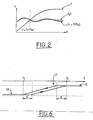
- FIG. 2 illustrates, on the same graph, an example of variation over time t: of the temperature T of the coolant, and of the first threshold temperature T 1 (Pm), which is a function of the average power .
- the circuit comprises a branch 4 provided with an electronically controlled actuator 14 and provided with means 9 forming a radiator.
- the radiator means 9 can be coupled to a fan motor unit 30, which can also be controlled by the control means 19.
- the information acquisition means 22 determine the temperature T of the cooling fluid, so that when the latter is greater than the second threshold temperature T 2 , the control means 19 regulate the flow in the radiator branch 4 so as to maintain the temperature T of the coolant around a setpoint value Tc determined.
- the set temperature Tc is the temperature of the coolant ensuring optimum operation of the engine 1.
- This setpoint temperature Tc is defined, for example, by modeling the engine concerned.
- the set temperature Tc is, for example, between 60 and 120 degrees, and preferably between 80 and 100 degrees.
- control means 19 cooperate with the information acquisition means 22 for determining the target temperature Tc as a function of the speed N and / or the torque C of the engine 1.
- the target temperature Tc decreases when the torque C of the motor 1 increases.
- the setpoint temperature Tc decreases when the speed N of the motor 1 increases.
- FIG. 3 illustrates an exemplary curve representative of the variation of the setpoint temperature Tc as a function of the torque C of the motor, at constant speed N.
- the curve representative of the variation of the set temperature Tc as a function of the torque C at constant speed N may have a general appearance comparable to that of the curve of FIG.
- the actuator 14 of the radiator branch 4 may consist of a thermostatic valve that can be controlled electronically.
- the valve 14 may contain a member adapted to expand or retract, to regulate the degree of opening of the valve according to its temperature.
- the expandable member may also be electrically heated to control the opening and closing of the valve in real time.
- FIG. 4 represents two examples of variation of the% O opening percentage of the thermostatic valve 14 of radiator as a function of the temperature T of the coolant.
- FIG. 4 illustrates two examples of regulation of the temperature T of the coolant around two different temperature Tc1, Tc2 respectively.
- the opening curve O of the thermostatic valve 14 has a first hysteresis h1 around the first setpoint temperature Tc1 and a second hysteresis h2 around the second setpoint temperature Tc2.
- the sequencing of the closing phases F1, progressive opening F2, opening F3, and progressive closing F4 of the valve 14 is symbolized by arrows.
- the first setpoint temperature Tc1 may correspond, for example, to a phase of high load on the motor, while the second setpoint temperature Tc2, which is higher, may correspond to a lower load on the motor.
- the actuator 14 of the radiator branch 4 may consist of an electronically controlled proportional valve.
- the control means 19 can increase the opening of the valve. 14 proportional.
- the control means 19 can reduce the opening of the valve 14 proportional.
- control means 19 can cooperate with the information acquisition means 22 to determine the temperature Ta of the intake air of the engine 1 and to increase the flow rate of the cooling fluid in the radiator branch 4 when the temperature Ta of the air intake of the engine 1 increases beyond a first threshold S1 determined.
- control means 19 can provide a maximum flow rate in the radiator branch 4 when the temperature Ta of the intake air of the engine 1 reaches a determined second threshold S2.
- the first S1 and second S2 temperature thresholds for the intake air can be of the order of 40 degrees and 60 degrees respectively.
- FIG. 5 represents an example of variation of the pulse or electric intensity I of control of the radiator valve 14, as a function of the temperature Ta of the intake air of the engine, at speed N, torque C and speed of the constant vehicle.
- I1 designates the electric pulse delivered to the actuator 14 (proportional solenoid valve or thermovalve) for a given setpoint temperature Tc1.
- This electrical pulse I1 which is between 0 and 100% of the maximum pulse, defines a determined partial opening of the actuator 14.
- the Electrical pulse 1 delivered to the actuator 14 tends to I1.
- the electric pulse I delivered to the actuator 14 increases and tends towards the maximum pulse (100%), that is to say to a total opening of the valve 14. This means that, for a given setpoint temperature Tc defining a given flow rate in the radiator branch 4, the increase in the intake temperature Ta can generate an increase in flow, even when the setpoint temperature Tc does not vary.
- control means 19 can cooperate with the information acquisition means 22 for determining the speed of the vehicle, so as to increase the speed of the vehicle. flow in said branch 4 when the speed of the vehicle increases beyond a first determined threshold.
- control means 19 can provide a maximum flow in the radiator branch 4 when the speed of the vehicle reaches a second determined threshold.
- the variation curve of the pulse or electrical intensity 1 for controlling the radiator valve 14 as a function of vehicle speed may have a general appearance similar to that of the curve of FIG. 5.
- the first and second vehicle speed thresholds may be of the order of half the maximum permitted speed and the maximum speed, respectively.
- the circuit 2 comprises another branch 5 provided with an electronically controlled actuator 15 and associated with means 10 forming a direct return of fluid or bypass.
- the control means 19 can regulate the circulation of the cooling fluid in the bypass branch 5 as a function of the temperature T of this fluid.
- the quantity of fluid allowed to circulate in the bypass branch 5 increases as the temperature of the fluid increases from the first T 1 to the second threshold temperature T 2 .
- the electronically controlled actuator 15 of the bypass branch is of the proportional type.
- the control means 19 can limit the flow of fluid in the bypass branch 5 to a determined leakage rate. That is, the actuator 15 of the bypass branch 5 is partially open Of. For example, the partial opening Of of the actuator 15 can provide a leakage flow in the bypass branch 5 between 1/50 to about 1/5 maximum flow from the branch 5.
- the control means 19 at least temporarily control the total opening O of the bypass actuator 15 (FIG. 6).
- the degree of opening of the actuator 15 may be at least temporarily proportional to the temperature T of the cooling fluid. More specifically, between T 1 and T 2 , the opening of the bypass actuator 15 increases when the temperature T of the fluid increases and decreases when the temperature T of the fluid decreases. The variation of the opening of the actuator 15 may be proportional to the temperature of the fluid T.
- the curve representative of the opening of the actuator 15 as a function of the temperature T of the fluid can exhibit a hysteresis H. That is to say that the increase in the opening of the actuator 15 begins. after the temperature of the liquid T exceeds the first reference temperature T 1 of a first determined value E. Likewise, the decrease in the opening of the actuator 15 begins after the temperature T of the liquid becomes lower, from a first determined value E, to the second reference temperature T 2 . That is to say that the openings and closures of the actuator 15 are made offset with respect to the temperature thresholds T 1 and T 2, respectively .
- the values E of these offsets are, for example, of the order of 5 degrees.
- control means 19 can control the actuator 15 of the branch 5 by-pass as a function of the opening and closing of the actuator 14 of the branch 4 radiator.
- FIG. 7 illustrates the percentage of opening% O of the actuators 15, 14 of the branches 5 of bypass and radiator 4 as a function of the temperature T of the coolant.
- the control means 19 can close the actuator 15 of the bypass branch 5 when the actuator 14 of the radiator branch 4 is Similarly, the actuator 15 of the branch 5 bypass is open O when the actuator 14 of the radiator branch 4 is closed F.
- the opening of the actuator 15 of the branch 5 by -pass is inversely proportional to the opening of the actuator 14 of the branch 4 radiator.
- closures and openings of the actuator 15 of the bypass branch 5 can be made with a temperature offset R determined with respect to the openings and closures of the actuator 14 of the radiator branch 4.
- the temperature offset R may be of the order of a few degrees, for example five degrees.
- control means 19 can control the ventilation means 30 as a function of the temperature of the coolant. More precisely, the speed of rotation of the ventilation means 30 can increase when the temperature T of the coolant increases.
- the speed V of rotation of the ventilation means 30 increases in proportion to the speed of variation of the temperature of the coolant. d T d t .
- FIG. 8 illustrates two examples of lines d1 and d2 representing the speed of rotation of the fan motor unit as a function of the temperature T of the liquid.
- the two straight lines d1 and d2 have different slopes each representative of a speed of variation d T d t the temperature T of the coolant.
- the speed of variation d T d t the temperature T of the coolant can be calculated by the control means 19.
- the ventilation means 30 are started when the temperature T of the cooling fluid is greater than the set temperature Tc and the flow rate of the cooling liquid in the radiator branch 4 is substantially maximum.
- control means 19 can cooperate with the information acquisition means 22 for determining the temperature of the air located under the hood of the vehicle, so as to start the ventilation means 30 when the temperature of the the air under the hood is above a certain threshold.
- the information acquisition means 22 may be shaped to detect a possible failure of at least one of the electronically controlled actuators.
- the control means 19 can ensure the free circulation of the fluid in at least some of the branches, and preferably in all branches. That is, when a system failure is detected, all valves in circuit 2 are open.
- the cooling device according to the invention while being of simple structure, makes it possible to manage the heat exchanges in real time and in an optimum manner.
Landscapes
- Engineering & Computer Science (AREA)
- Chemical & Material Sciences (AREA)
- Combustion & Propulsion (AREA)
- Mechanical Engineering (AREA)
- General Engineering & Computer Science (AREA)
- Cooling, Air Intake And Gas Exhaust, And Fuel Tank Arrangements In Propulsion Units (AREA)
- Air-Conditioning For Vehicles (AREA)
Claims (11)
- Verfahren zum Kühlen eines Kraftfahrzeug-Motors, das darin besteht, das Volumen und den Durchsatz eines flüssigen Kühlmittels in einem Hydraulikkreis (2) zu regeln, der mit einem Zweig (4) mit einem elektronisch gesteuerten Wirkglied (14) und mit Mitteln (9), die einen Radiator bilden, versehen ist, wobei das Verfahren einen ersten Schritt umfasst, in dem die Temperatur (T) des Kühlfluids bestimmt wird, sowie einen Schritt, in dem diese Temperatur mit einer bestimmten Grenztemperatur (T2) verglichen wird, ab der der Motor (1) als "heiß" bezeichnet wird, wobei, wenn die Temperatur (T) des Fluids höher ist als die Grenztemperatur (T2), der Durchsatz im Radiatorzweig (4) so geregelt wird, dass die Temperatur (T) der Kühlflüssigkeit um einen bestimmten Einstellwert (Tc) herum gehalten wird, wobei die Kurve für die Öffnung (O) des thermostatischen Ventils (4) in Abhängigkeit von der Temperatur (T) des Kühlfluids eine Hysterese (h1, h2) um die Einstelltemperatur (Tc1, Tc2) herum aufweist, sodass die Temperatur (T) der Kühlflüssigkeit auf die Einstelltemperatur (Tc1, Tc2) geregelt wird, dadurch gekennzeichnet, dass die Temperatur (Ta) der Einlassluft des Motors (1) bestimmt wird, sodass der Durchsatz im Zweig (4) erhöht wird, wenn die Temperatur (Ta) der Einlassluft des Motors (1) einen bestimmten ersten Grenzwert (S1) überschreitet.
- Vorrichtung zum Kühlen eines Kraftfahrzeug-Motors mit einem Hydraulikkreis (2) für flüssiges Kühlmittel mit einer Umlaufpumpe (3), die dieses durch den Motor (1) des Fahrzeugs und verschiedene Zweige (4, 5, 6, 7, 8, 44) des Kreises pumpt, in denen die thermischen Anlagen (9, 10, 11, 12, 13, 140, 150, 160) des Fahrzeugs angeordnet sind, wobei zumindest bestimmte Zweige (4, 5, 6, 7, 8, 44) des Kreises (2) mit elektronisch gesteuerten Wirkgliedern (14, 15, 16, 17, 18, 29) zum Regeln der Zirkulation des Fluids in ihnen ausgestattet sind, wobei die Vorrichtung Mittel (22) zum Erfassen von Informationen über die Betriebsbedingungen des Fahrzeugs umfasst, die mit Mitteln (19) zum Steuern der Funktionsweise der Wirkglieder (14, 15, 16, 17, 18, 29) verbunden sind, um das Volumen und den Durchsatz an Fluid, das im Hydraulikkreis (2) zirkuliert, im Hinblick auf eine optimierte Funktionsweise des Motors (1) zu regeln, wobei der Kreis (2) einen Zweig (4) aufweist, der mit einem elektronisch gesteuerten Wirkglied (14) und Mitteln (9), die einen Radiator bilden, versehen ist, wobei die Informationserfassungsmittel (22) die Temperatur (T) des Kühlfluids ermitteln können, sodass wenn die Temperatur (T) des Fluids einen bestimmten Grenzwert (T2) übersteigt, ab dem der Motor (1) als "heiß" bezeichnet wird, die Steuermittel (19) den Durchsatz im Radiatorzweig (4) derart steuern, dass die Temperatur (T) der Kühlflüssigkeit um einen bestimmten Einstellwert (Tc) herum gehalten wird, wobei das Wirkglied (14) des Radiatorzweigs (4) aus einem elektronisch steuerbaren thermostatischen Ventil besteht und wobei die Kurve für die Öffnung (O) des thermostatischen Ventils (4) in Abhängigkeit von der Temperatur (T) des Kühlfluids eine Hysterese (h1, h2) um die Einstelltemperatur (Tc1, Tc2) aufweist, sodass die Temperatur (T) der Kühlflüssigkeit auf die Einstelltemperatur (Tc1, Tc2) geregelt wird, dadurch gekennzeichnet, dass die Steuermittel (19) mit den Informationserfassungsmitteln (22) zusammenwirken, um die Temperatur (Ta) der Einlassluft des Motors (1) zu bestimmen, sodass der Durchsatz im Zweig (4) erhöht wird, wenn die Temperatur (Ta) der Einlassluft des Motors (1) einen bestimmten ersten Grenzwert (S1) überschreitet.
- Vorrichtung nach Anspruch 2, dadurch gekennzeichnet, dass die Einstelltemperatur (Tc) zwischen ungefähr 60 und 120 Grad liegt.
- Vorrichtung nach Anspruch 2 oder 3, dadurch gekennzeichnet, dass die Steuermittel (19) den Durchsatz im Radiatorzweig (4) erhöhen, wenn die Temperatur (Ta) der Einlassluft des Motors (1) steigt, sodass für einen maximalen Durchsatz im Zweig (4) gesorgt ist, wenn die Temperatur (Ta) der Einlassluft des Motors (1) einen bestimmten zweiten Grenzwert (S2) erreicht.
- Vorrichtung nach einem der Ansprüche 2 bis 4, dadurch gekennzeichnet, dass die Steuermittel (19) mit den Informationserfassungsmitteln (22) zusammenwirken, um die Geschwindigkeit des Fahrzeugs zu bestimmen, sodass der Durchsatz im Zweig (4) erhöht wird, wenn die Geschwindigkeit des Fahrzeugs einen bestimmten ersten Grenzwert überschreitet.
- Vorrichtung nach Anspruch 5, dadurch gekennzeichnet, dass die Steuermittel (19) den Durchsatz im Radiatorzweig (4) erhöhen, wenn die Geschwindigkeit des Fahrzeugs steigt, sodass für einen maximalen Durchsatz im Zweig (4) gesorgt ist, wenn die Geschwindigkeit des Fahrzeugs einen bestimmten zweiten Grenzwert erreicht.
- Vorrichtung nach einem der Ansprüche 2 bis 6, dadurch gekennzeichnet, dass sie Lüftermittel (30) oder einen Lüftersatz aufweist, die mit den Radiatormitteln (9) zusammenwirken können, wobei die Steuermittel (19) die Lüftermittel (30) in Abhängigkeit von der Temperatur (T) der Kühlflüssigkeit steuern, sodass die Drehgeschwindigkeit (V) der Lüftermittel (30) zunimmt, wenn die Temperatur (T) des Kühlfluids steigt.
- Vorrichtung nach Anspruch 7, dadurch gekennzeichnet, dass die Zunahme der Drehgeschwindigkeit (V) der Lüftermittel (30) in Abhängigkeit von der Änderungsgeschwindigkeit der Temperatur (T) der Kühlflüssigkeit gesteuert wird.
- Vorrichtung nach Anspruch 8, dadurch gekennzeichnet, dass die Drehgeschwindigkeit der Lüftermittel (30) in Abhängigkeit von der Temperatur (T) der Kühlflüssigkeit eine Gerade beschreibt, deren Steigung proportional zur Änderungsgeschwindigkeit (dT) der Temperatur der Kühlflüssigkeit ist.
- Vorrichtung nach einem der Ansprüche 7 bis 9, dadurch gekennzeichnet, dass die Lüftermittel (30) in Gang gesetzt werden, wenn die Temperatur (T) des Kühlfluids höher ist als die Einstelltemperatur (Tc) und der Durchsatz der Kühlflüssigkeit im Radiatorzweig (4) im Wesentlichen maximal ist.
- Vorrichtung nach einem der Ansprüche 7 bis 10, dadurch gekennzeichnet, dass die Steuermittel (19) mit den Informationserfassungsmitteln (22) zusammenwirken, um die Temperatur der Luft unter der Motorhaube des Fahrzeugs zu ermitteln, sodass die Lüftermittel (30) in Gang gesetzt werden, wenn die Temperatur der Luft unter der Motorhaube einen bestimmten Grenzwert der Temperatur der Flüssigkeit an verschiedenen Stellen der Schleife übersteigt.
Applications Claiming Priority (3)
| Application Number | Priority Date | Filing Date | Title |
|---|---|---|---|
| FR0003436A FR2806444B1 (fr) | 2000-03-17 | 2000-03-17 | Dispositif de refroidissement d'un moteur de vehicule automobile |
| FR0003436 | 2000-03-17 | ||
| PCT/FR2001/000238 WO2001069056A1 (fr) | 2000-03-17 | 2001-01-25 | Procede et dispositif de refroidissement d'un moteur de vehicule automobile |
Publications (2)
| Publication Number | Publication Date |
|---|---|
| EP1264086A1 EP1264086A1 (de) | 2002-12-11 |
| EP1264086B1 true EP1264086B1 (de) | 2006-10-04 |
Family
ID=8848203
Family Applications (1)
| Application Number | Title | Priority Date | Filing Date |
|---|---|---|---|
| EP01907697A Expired - Lifetime EP1264086B1 (de) | 2000-03-17 | 2001-01-25 | Verfahren und einrichtung zur kühlung einer brennkraftmaschine eines kraftfahrzeugs |
Country Status (7)
| Country | Link |
|---|---|
| US (1) | US6880495B2 (de) |
| EP (1) | EP1264086B1 (de) |
| JP (1) | JP4606683B2 (de) |
| DE (1) | DE60123587T2 (de) |
| ES (1) | ES2273806T3 (de) |
| FR (1) | FR2806444B1 (de) |
| WO (1) | WO2001069056A1 (de) |
Families Citing this family (21)
| Publication number | Priority date | Publication date | Assignee | Title |
|---|---|---|---|---|
| US6867395B2 (en) * | 2002-10-22 | 2005-03-15 | General Motors Corporation | Variable flow thermostat and method for variably controlling engine temperature |
| JP2004353602A (ja) * | 2003-05-30 | 2004-12-16 | Nippon Thermostat Co Ltd | 電子制御サーモスタットの制御方法 |
| CA2474415A1 (en) * | 2004-07-15 | 2006-01-15 | Gerald Hayes | Auxillary cooler for an engine located in a building |
| US7725238B2 (en) * | 2004-11-19 | 2010-05-25 | Perkins Michael T | System and method for smart system control for flowing fluid conditioners |
| FR2896271B1 (fr) * | 2006-01-19 | 2012-08-17 | Renault Sas | Procede et dispositif de regulation de la temperature d'un moteur a combustion interne |
| DE102009012534A1 (de) * | 2009-03-10 | 2010-09-16 | Audi Ag | Selbstregelndes Thermostatventil sowie Kühlsystem für ein Brennkraftmaschine |
| US8215283B2 (en) * | 2009-04-06 | 2012-07-10 | Honda Motor Co., Ltd. | Cooling system for variable cylinder engines |
| US8303465B2 (en) * | 2009-10-30 | 2012-11-06 | Ford Global Technologies, Llc | Method for controlling engine temperature of an engine |
| US8948946B2 (en) * | 2012-11-29 | 2015-02-03 | GM Global Technology Operations LLC | Hybrid thermal system with device-specific control logic |
| EP3056706A1 (de) | 2015-02-16 | 2016-08-17 | Honeywell International Inc. | Ansatz zur nachbehandlungssystemmodellierung und modellidentifizierung |
| EP3125052B1 (de) | 2015-07-31 | 2020-09-02 | Garrett Transportation I Inc. | Quadratischer programmlöser für mpc mit variabler anordnung |
| US10272779B2 (en) | 2015-08-05 | 2019-04-30 | Garrett Transportation I Inc. | System and approach for dynamic vehicle speed optimization |
| US10040335B2 (en) * | 2016-03-24 | 2018-08-07 | GM Global Technology Operations LLC | Thermal management system for a vehicle, and a method of controlling the same |
| US10124750B2 (en) | 2016-04-26 | 2018-11-13 | Honeywell International Inc. | Vehicle security module system |
| US10036338B2 (en) * | 2016-04-26 | 2018-07-31 | Honeywell International Inc. | Condition-based powertrain control system |
| US10728249B2 (en) | 2016-04-26 | 2020-07-28 | Garrett Transporation I Inc. | Approach for securing a vehicle access port |
| EP3548729B1 (de) | 2016-11-29 | 2023-02-22 | Garrett Transportation I Inc. | Inferenzflusssensor |
| US11057213B2 (en) | 2017-10-13 | 2021-07-06 | Garrett Transportation I, Inc. | Authentication system for electronic control unit on a bus |
| KR102371255B1 (ko) | 2017-10-17 | 2022-03-04 | 현대자동차 주식회사 | 냉각수 제어 밸브유닛의 제어방법 |
| CN112954952B (zh) * | 2021-01-20 | 2023-04-07 | 中车株洲电力机车有限公司 | 轨道列车及其散热系统、散热方法 |
| CN115962040B (zh) * | 2023-02-02 | 2024-06-11 | 重庆赛力斯新能源汽车设计院有限公司 | 一种发动机冷却控制方法、系统、设备及存储介质 |
Citations (1)
| Publication number | Priority date | Publication date | Assignee | Title |
|---|---|---|---|---|
| FR2456838A1 (fr) * | 1979-05-18 | 1980-12-12 | Sev Marchal | Vanne a action thermostatique destinee a un circuit de refroidissement de moteur a combustion interne |
Family Cites Families (29)
| Publication number | Priority date | Publication date | Assignee | Title |
|---|---|---|---|---|
| JPS58124017A (ja) * | 1982-01-19 | 1983-07-23 | Nippon Denso Co Ltd | エンジンの冷却系制御装置 |
| US4489680A (en) * | 1984-01-23 | 1984-12-25 | Borg-Warner Corporation | Engine temperature control system |
| US4930455A (en) | 1986-07-07 | 1990-06-05 | Eaton Corporation | Controlling engine coolant flow and valve assembly therefor |
| DE3716555A1 (de) | 1987-05-18 | 1988-12-08 | Bayerische Motoren Werke Ag | Befuell-, entlueftungs- und drucksteuer-vorrichtung fuer den fluessigkeits-kuehlkreis von kraft- und arbeitsmaschinen, insbesondere brennkraftmaschinen |
| DE4033261C2 (de) * | 1990-10-19 | 1995-06-08 | Freudenberg Carl Fa | Temperaturgesteuerter Kühlkreis einer Verbrennungskraftmaschine |
| DE4104093A1 (de) * | 1991-02-11 | 1992-08-13 | Behr Gmbh & Co | Kuehlanlage fuer ein fahrzeug mit verbrennungsmotor |
| DE4109498B4 (de) * | 1991-03-22 | 2006-09-14 | Robert Bosch Gmbh | Vorrichtung und Verfahren zur Regelung der Temperatur einer Brennkraftmaschine |
| US5241926A (en) | 1991-08-09 | 1993-09-07 | Mazda Motor Corporation | Engine cooling apparatus |
| DE69325044T2 (de) * | 1992-02-19 | 1999-09-30 | Honda Giken Kogyo K.K., Tokio/Tokyo | Maschinenkühlanlage |
| DE4324178A1 (de) * | 1993-07-19 | 1995-01-26 | Bayerische Motoren Werke Ag | Kühlanlage für einen Verbrennungsmotor eines Kraftfahrzeuges mit einem Thermostatventil, das ein elektrisch beheizbares Dehnstoffelement enthält |
| JPH0821241A (ja) * | 1994-07-01 | 1996-01-23 | Yamaha Motor Co Ltd | エンジン駆動式ヒートポンプ装置 |
| FR2722244B1 (fr) | 1994-07-07 | 1996-08-23 | Valeo Thermique Moteur Sa | Dispositif de thermoregulation d'un moteur thermique |
| US5582138A (en) * | 1995-03-17 | 1996-12-10 | Standard-Thomson Corporation | Electronically controlled engine cooling apparatus |
| DE19519377A1 (de) | 1995-05-26 | 1996-11-28 | Bayerische Motoren Werke Ag | Kühlanlage mit elektrisch regelbarem Stellglied |
| DE19607638C1 (de) | 1996-02-29 | 1997-06-19 | Porsche Ag | Kühlkreislauf einer Brennkraftmaschine |
| JP3675108B2 (ja) * | 1996-06-24 | 2005-07-27 | トヨタ自動車株式会社 | 水温センサの故障診断装置 |
| US6182617B1 (en) * | 1996-06-17 | 2001-02-06 | Donald Bigcharles | Apparatus for internal combustion engine |
| IT1291190B1 (it) * | 1997-03-13 | 1998-12-29 | Gate Spa | Sistema di raffreddamento per un motore a combustione interna, particolarmente per autoveicoli |
| DE19719792B4 (de) * | 1997-05-10 | 2004-03-25 | Behr Gmbh & Co. | Verfahren und Vorrichtung zur Regulierung der Temperatur eines Mediums |
| AT410243B (de) * | 1997-07-23 | 2003-03-25 | Tcg Unitech Ag | Mehrwegventil |
| IT1293664B1 (it) * | 1997-08-01 | 1999-03-08 | C R F Societa Conosrtile Per A | Sistema di raffreddamento per motore a combustione interna di autoveicolo |
| FR2776707B1 (fr) | 1998-03-31 | 2000-10-06 | Peugeot | Systeme de gestion des echanges thermiques dans un vehicule automobile |
| US5950576A (en) | 1998-06-30 | 1999-09-14 | Siemens Canada Limited | Proportional coolant valve |
| JP3552543B2 (ja) * | 1998-07-29 | 2004-08-11 | 株式会社デンソー | 液冷式内燃機関の冷却装置 |
| US6055947A (en) * | 1999-01-14 | 2000-05-02 | Tosok Corporation | Engine cooling water control system |
| DE19948160B4 (de) | 1999-10-07 | 2010-07-15 | Wilhelm Kuhn | Kühlvorrichtung für eine flüssigkeitsgekühlte Brennkraftmaschine eines Kraftfahrzeuges |
| DE19960190A1 (de) * | 1999-12-14 | 2001-07-05 | Bosch Gmbh Robert | Regelventil |
| EP1239129B1 (de) * | 2001-03-06 | 2007-10-31 | Calsonic Kansei Corporation | Kühlungssystem für eine wassergekühlte Brennkraftmaschine und Steuerverfahren dafür |
| JP2003003846A (ja) * | 2001-06-21 | 2003-01-08 | Aisan Ind Co Ltd | エンジン冷却装置 |
-
2000
- 2000-03-17 FR FR0003436A patent/FR2806444B1/fr not_active Expired - Fee Related
-
2001
- 2001-01-25 EP EP01907697A patent/EP1264086B1/de not_active Expired - Lifetime
- 2001-01-25 DE DE60123587T patent/DE60123587T2/de not_active Expired - Lifetime
- 2001-01-25 WO PCT/FR2001/000238 patent/WO2001069056A1/fr not_active Ceased
- 2001-01-25 JP JP2001567912A patent/JP4606683B2/ja not_active Expired - Fee Related
- 2001-01-25 US US10/221,153 patent/US6880495B2/en not_active Expired - Fee Related
- 2001-01-25 ES ES01907697T patent/ES2273806T3/es not_active Expired - Lifetime
Patent Citations (1)
| Publication number | Priority date | Publication date | Assignee | Title |
|---|---|---|---|---|
| FR2456838A1 (fr) * | 1979-05-18 | 1980-12-12 | Sev Marchal | Vanne a action thermostatique destinee a un circuit de refroidissement de moteur a combustion interne |
Also Published As
| Publication number | Publication date |
|---|---|
| US6880495B2 (en) | 2005-04-19 |
| FR2806444A1 (fr) | 2001-09-21 |
| DE60123587D1 (de) | 2006-11-16 |
| US20030196612A1 (en) | 2003-10-23 |
| DE60123587T2 (de) | 2007-08-09 |
| JP2003528241A (ja) | 2003-09-24 |
| EP1264086A1 (de) | 2002-12-11 |
| ES2273806T3 (es) | 2007-05-16 |
| FR2806444B1 (fr) | 2002-06-07 |
| JP4606683B2 (ja) | 2011-01-05 |
| WO2001069056A1 (fr) | 2001-09-20 |
Similar Documents
| Publication | Publication Date | Title |
|---|---|---|
| EP1264086B1 (de) | Verfahren und einrichtung zur kühlung einer brennkraftmaschine eines kraftfahrzeugs | |
| EP1409856B1 (de) | Verfahren und einrichtung zur kühlung einer brennkraftmaschine eines kraftfahrzeugs | |
| WO1984000578A1 (fr) | Dispositif de refroidissement d'un moteur a combustion interne | |
| EP3559426B1 (de) | Verfahren zum betrieb eines kühlsystems für ein hybrides elektrofahrzeug mit einem kühlflüssigkeitstransferkreis | |
| FR2843168A1 (fr) | Procede de commande d'un circuit de refroidissement et de chauffage d'un vehicule automobile | |
| EP1276976B1 (de) | Verfahren und einrichtung zur kühlung einer brennkraftmaschine eines kraftfahrzeugs | |
| EP2010769A1 (de) | System und verfahren zur steuerung der temperatur eines aufgeladenen motors mit einem abgasrückführungskreislauf | |
| FR2796987A1 (fr) | Dispositif de regulation du refroidissement d'un moteur thermique de vehicule automobile | |
| EP1268992B1 (de) | Verfahren und einrichtung zur kühlung einer brennkraftmaschine eines kraftfahrzeugs | |
| FR2956158A1 (fr) | Systeme multivoies de controle d'un circuit de refroidissement d'un moteur a combustion interne | |
| WO1998029645A1 (fr) | Procede et installation de recuperation de chaleur dans de l'air de suralimentation d'un moteur | |
| FR3005609A1 (fr) | Circuit de refroidissement de groupe motopropulseur optimisant la montee en temperature de la boite de vitesse | |
| EP1233157B1 (de) | Verfahren und Einrichtung zur Kühlung einer Brennkraftmaschine eines Kraftfahrzeugs | |
| EP2126308A1 (de) | System und verfahren zur antriebskühlung bei einem auto | |
| FR2804721A1 (fr) | Dispositif de refroidissement d'un moteur de vehicule automobile | |
| EP3423690B1 (de) | System zur steuerung einer vorrichtung zur thermischen regelung eines kühlkreislaufs eines kraftfahrzeugmotors und verfahren zur steuerung des besagten steuerungssystems | |
| FR2799505A1 (fr) | Systeme de refroidissement d'un moteur de vehicule automobile | |
| FR2910537A1 (fr) | Dispositif et procede de regulation du debit de l'air envoye au travers d'un echangeur de chaleur pour moteur a combustion interne de vehicule automobile | |
| FR3040739B1 (fr) | Systeme de refroidissement pour un moteur a combustion interne, notamment de vehicule automobile | |
| EP3899224B1 (de) | Vorrichtung zur kühlung eines turboladers eines hybridmotors | |
| FR3084914A1 (fr) | Circuit de refroidissement d'un groupe motopropulseur thermique ou hybride et procede de commande d'un tel circuit | |
| EP3557177B1 (de) | Kühlradiator mit integriertem by-pass und kühlkreislauf | |
| FR2920825A3 (fr) | Dispositif de refroidissement pour moteur a combustion interne regule a partir d'un circuit de recirculation controle par une vanne | |
| FR3066537B1 (fr) | Procede de regulation d’une temperature d’huile de lubrification d’un moteur thermique a deux flux de sortie | |
| FR2793842A1 (fr) | Dispositif electronique de regulation du refroidissement d'un moteur thermique de vehicule automobile |
Legal Events
| Date | Code | Title | Description |
|---|---|---|---|
| PUAI | Public reference made under article 153(3) epc to a published international application that has entered the european phase |
Free format text: ORIGINAL CODE: 0009012 |
|
| 17P | Request for examination filed |
Effective date: 20020920 |
|
| AK | Designated contracting states |
Kind code of ref document: A1 Designated state(s): AT BE CH CY DE DK ES FI FR GB GR IE IT LI LU MC NL PT SE TR |
|
| RBV | Designated contracting states (corrected) |
Designated state(s): AT BE CH CY DE ES GB IT LI |
|
| GRAP | Despatch of communication of intention to grant a patent |
Free format text: ORIGINAL CODE: EPIDOSNIGR1 |
|
| RBV | Designated contracting states (corrected) |
Designated state(s): DE ES GB IT |
|
| GRAS | Grant fee paid |
Free format text: ORIGINAL CODE: EPIDOSNIGR3 |
|
| GRAA | (expected) grant |
Free format text: ORIGINAL CODE: 0009210 |
|
| AK | Designated contracting states |
Kind code of ref document: B1 Designated state(s): DE ES GB IT |
|
| PG25 | Lapsed in a contracting state [announced via postgrant information from national office to epo] |
Ref country code: IT Free format text: LAPSE BECAUSE OF FAILURE TO SUBMIT A TRANSLATION OF THE DESCRIPTION OR TO PAY THE FEE WITHIN THE PRESCRIBED TIME-LIMIT;WARNING: LAPSES OF ITALIAN PATENTS WITH EFFECTIVE DATE BEFORE 2007 MAY HAVE OCCURRED AT ANY TIME BEFORE 2007. THE CORRECT EFFECTIVE DATE MAY BE DIFFERENT FROM THE ONE RECORDED. Effective date: 20061004 |
|
| REG | Reference to a national code |
Ref country code: GB Ref legal event code: FG4D Free format text: NOT ENGLISH |
|
| REF | Corresponds to: |
Ref document number: 60123587 Country of ref document: DE Date of ref document: 20061116 Kind code of ref document: P |
|
| GBT | Gb: translation of ep patent filed (gb section 77(6)(a)/1977) |
Effective date: 20061108 |
|
| REG | Reference to a national code |
Ref country code: ES Ref legal event code: FG2A Ref document number: 2273806 Country of ref document: ES Kind code of ref document: T3 |
|
| PLBE | No opposition filed within time limit |
Free format text: ORIGINAL CODE: 0009261 |
|
| STAA | Information on the status of an ep patent application or granted ep patent |
Free format text: STATUS: NO OPPOSITION FILED WITHIN TIME LIMIT |
|
| 26N | No opposition filed |
Effective date: 20070705 |
|
| REG | Reference to a national code |
Ref country code: GB Ref legal event code: 746 Effective date: 20080304 |
|
| PGFP | Annual fee paid to national office [announced via postgrant information from national office to epo] |
Ref country code: ES Payment date: 20090113 Year of fee payment: 9 |
|
| PGFP | Annual fee paid to national office [announced via postgrant information from national office to epo] |
Ref country code: GB Payment date: 20081229 Year of fee payment: 9 |
|
| PGFP | Annual fee paid to national office [announced via postgrant information from national office to epo] |
Ref country code: IT Payment date: 20090117 Year of fee payment: 9 |
|
| GBPC | Gb: european patent ceased through non-payment of renewal fee |
Effective date: 20100125 |
|
| PG25 | Lapsed in a contracting state [announced via postgrant information from national office to epo] |
Ref country code: GB Free format text: LAPSE BECAUSE OF NON-PAYMENT OF DUE FEES Effective date: 20100125 |
|
| PG25 | Lapsed in a contracting state [announced via postgrant information from national office to epo] |
Ref country code: IT Free format text: LAPSE BECAUSE OF NON-PAYMENT OF DUE FEES Effective date: 20100125 |
|
| REG | Reference to a national code |
Ref country code: ES Ref legal event code: FD2A Effective date: 20110407 |
|
| PG25 | Lapsed in a contracting state [announced via postgrant information from national office to epo] |
Ref country code: ES Free format text: LAPSE BECAUSE OF NON-PAYMENT OF DUE FEES Effective date: 20110328 |
|
| PG25 | Lapsed in a contracting state [announced via postgrant information from national office to epo] |
Ref country code: ES Free format text: LAPSE BECAUSE OF NON-PAYMENT OF DUE FEES Effective date: 20100126 |
|
| PGFP | Annual fee paid to national office [announced via postgrant information from national office to epo] |
Ref country code: DE Payment date: 20121226 Year of fee payment: 13 |
|
| REG | Reference to a national code |
Ref country code: DE Ref legal event code: R119 Ref document number: 60123587 Country of ref document: DE |
|
| REG | Reference to a national code |
Ref country code: DE Ref legal event code: R119 Ref document number: 60123587 Country of ref document: DE Effective date: 20140801 |
|
| PG25 | Lapsed in a contracting state [announced via postgrant information from national office to epo] |
Ref country code: DE Free format text: LAPSE BECAUSE OF NON-PAYMENT OF DUE FEES Effective date: 20140801 |