EP1264099B1 - Piston sleeve - Google Patents
Piston sleeve Download PDFInfo
- Publication number
- EP1264099B1 EP1264099B1 EP01920214A EP01920214A EP1264099B1 EP 1264099 B1 EP1264099 B1 EP 1264099B1 EP 01920214 A EP01920214 A EP 01920214A EP 01920214 A EP01920214 A EP 01920214A EP 1264099 B1 EP1264099 B1 EP 1264099B1
- Authority
- EP
- European Patent Office
- Prior art keywords
- piston sleeve
- positioning surface
- sleeve
- internal combustion
- combustion engine
- Prior art date
- Legal status (The legal status is an assumption and is not a legal conclusion. Google has not performed a legal analysis and makes no representation as to the accuracy of the status listed.)
- Expired - Lifetime
Links
- 238000002485 combustion reaction Methods 0.000 claims description 25
- 239000002826 coolant Substances 0.000 claims description 25
- 230000006835 compression Effects 0.000 claims description 16
- 238000007906 compression Methods 0.000 claims description 16
- 238000004519 manufacturing process Methods 0.000 claims 1
- 238000000034 method Methods 0.000 claims 1
- 239000000463 material Substances 0.000 description 5
- 238000001816 cooling Methods 0.000 description 4
- 230000002528 anti-freeze Effects 0.000 description 3
- XLYOFNOQVPJJNP-UHFFFAOYSA-N water Substances O XLYOFNOQVPJJNP-UHFFFAOYSA-N 0.000 description 3
- 230000008602 contraction Effects 0.000 description 2
- 230000007797 corrosion Effects 0.000 description 2
- 238000005260 corrosion Methods 0.000 description 2
- 230000004048 modification Effects 0.000 description 2
- 238000012986 modification Methods 0.000 description 2
- 238000005498 polishing Methods 0.000 description 2
- 238000007789 sealing Methods 0.000 description 2
- 238000005452 bending Methods 0.000 description 1
- 238000005520 cutting process Methods 0.000 description 1
- 230000007850 degeneration Effects 0.000 description 1
- 239000000446 fuel Substances 0.000 description 1
- 239000000314 lubricant Substances 0.000 description 1
- 238000005461 lubrication Methods 0.000 description 1
- 238000003754 machining Methods 0.000 description 1
- 230000013011 mating Effects 0.000 description 1
Images

Classifications
-
- F—MECHANICAL ENGINEERING; LIGHTING; HEATING; WEAPONS; BLASTING
- F02—COMBUSTION ENGINES; HOT-GAS OR COMBUSTION-PRODUCT ENGINE PLANTS
- F02F—CYLINDERS, PISTONS OR CASINGS, FOR COMBUSTION ENGINES; ARRANGEMENTS OF SEALINGS IN COMBUSTION ENGINES
- F02F1/00—Cylinders; Cylinder heads
- F02F1/02—Cylinders; Cylinder heads having cooling means
- F02F1/10—Cylinders; Cylinder heads having cooling means for liquid cooling
- F02F1/16—Cylinder liners of wet type
-
- F—MECHANICAL ENGINEERING; LIGHTING; HEATING; WEAPONS; BLASTING
- F02—COMBUSTION ENGINES; HOT-GAS OR COMBUSTION-PRODUCT ENGINE PLANTS
- F02B—INTERNAL-COMBUSTION PISTON ENGINES; COMBUSTION ENGINES IN GENERAL
- F02B3/00—Engines characterised by air compression and subsequent fuel addition
- F02B3/06—Engines characterised by air compression and subsequent fuel addition with compression ignition
Definitions
- This invention relates to a piston sleeve for a high compression internal combustion engine comprising: a tubular member having a top surface, a tubular member axis and a bottom surface; a radial positioning surface adjacent to the top surface; an axial positioning surface that faces axially toward the bottom surface and is between the top surface and the bottom surface; a radially outward facing coolant contact surface between the radial positioning surface and the axial positioning surface; a skirt extending from the axial positioning surface to the bottom surface.
- Such a piston sleeve is known from US-A-4244330.
- Piston sleeves employed in high compression engines have generally had a flange on their top or head end that is clamped in place between the block and the cylinder head.
- the skirt of these piston sleeves is permitted to float due to thermal expansion and contraction.
- the elongation and contraction of piston sleeves that are dry has not been a problem.
- cooling capacity must be somewhat lager with dry sleeves that with wet sleeves to insure adequate cooling.
- High compression engines designed in recent years have generally had wet piston sleeves to improve cooling, reduce the coolant capacity requirement for their cooling systems and thereby reduce vehicle weight.
- Piston sleeves with a top flange, as described above, that are in direct contact with engine coolant require sealing devices to seal between the sleeve skirt and the block. Such seals have durability problems.
- Engine designers are now designing engines with wet piston sleeves, each of which is anchored on the block by a radially extending flange that is mid way between the top end and the crankshaft or bottom end.
- the radially extending flange has an axial positioning surface in direct contact with a stop surface on the engine block.
- the sleeve is axially loaded between the cylinder head and the engine block stop surface to eliminate leakage of gasses and coolant.
- a seal device is not required between the block stop surface and the radially extending flange mid way between the sleeve ends.
- an appropriate seal device can also be employed if desired.
- the axial load required to seal between a piston sleeve and the cylinder head and a block stop surface is substantial.
- the seal between the top end of the sleeve and the cylinder head must prevent the passage of compressed air prior to combustion and the pressure of hot gasses following combustion. In high output diesel engines that are turbocharged, the pressure in the combustion chamber is substantial.
- the seal between the axial positioning surface and the block stop surface generally does not require a large axial load. However, both seals must maintain a seal when the engine is cold as well as when the engine is hot.
- the axial load on a piston sleeve with a mid stop that is required to prevent leakage between the top of a sleeve and a cylinder head and to prevent leakage between an axial positioning surface on the radial flange and a block stop surface under all possible operating conditions is large.
- the inside walls of the piston sleeves should be cylindrical or close to cylindrical under normal operating conditions.
- the piston sleeve for a high compression internal combustion engine is a tubular member.
- the tubular member has a top surface, that is perpendicular to an axis of the tubular member, and a bottom surface.
- a radial positioning surface is adjacent to the top surface.
- An axial positioning surface faces axially toward the bottom surface and is between the top surface and the bottom surface.
- a radially outward facing coolant contact surface is between the radial positioning surface and the axial positioning surface.
- a skirt extends from the axial positioning surface to the bottom surface.
- a profiled radially inward facing surface extends substantially from the top surface to the bottom surface. The profile becomes substantially cylindrical when the piston sleeve is in a high compression internal combustion engine block and a predetermined axial compression force is applied to the top surface and to the axial positioning surface.
- the piston sleeve provides a joint between its top surface and a cylinder head that holds products of combustion in the combustion chamber.
- Contact between the axial positioning surface of the piston sleeve and the engine block retains engine coolant and keeps coolant out of the crankcase without the use of a seal device.
- the cylindrical cylinder wall surface that is formed inside the sleeve during normal operation reduces piston ring wear, piston wear and sleeve wear.
- the cylindrical surface also reduces oil consumption blow by and undesirable emissions from the engine.
- Piston sleeves for diesel engines with profiled cylinder walls as described above can be pressed into an internal combustion engine and ready to use as received from the factory. Expensive and time consuming honeing, polishing and cutting operations in the field are eliminated.
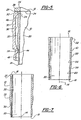
- a piston sleeve 10 for an internal combustion engine 12 is a tubular member with an axis 14.
- the sleeve 10 has a top surface 16, a bottom surface 18, a radially inner surface 20 and an outer surface 22.
- the top surface 16 is in a plane that is perpendicular to the axis 14.
- the bottom surface 18 is also in a plane that is perpendicular to the axis 14.
- the top surface 16 is separated from a surface 24 on the cylinder head 26 by a gasket 25.
- Normally the block top surface 28 of the engine block 30 is perpendicular to the axis 14 of the piston sleeve 10. It is convenient to have the sleeve top surface 16 in a plane that is parallel to the top surface 28 of the engine block 30.
- top surface 16 of the piston sleeve 10 By placing the top surface 16 of the piston sleeve 10 in a plane that is perpendicular to the axis 14, force exerted on the sleeve by the cylinder head 26 is exerted in a direction that is parallel to the axis 14. There is no uneven force on the sleeve 10 that is transverse to the axis 14 and would tend to bend the sleeve.
- the bottom surface 18 is not in direct contact with any other object or surface.
- the bottom surface 18 of the sleeve 10 can be any shape within limits.
- the outer surface 22 of the piston sleeve 10 has a radially positioning surface 32 adjacent to the top surface 16.
- This positioning surface 32 has a diameter that exceeds the diameter of the bore 34 in the internal combustion engine block 30.
- a press forces the radial positioning surface 32 into the bore 34 forming an interference fit that prevents leakage of coolant from the coolant jacket 36.
- An axial positioning surface 38 on the piston sleeve 10 is between the top surface 16 and the bottom surface 18 and adjacent to the lower portion of the coolant jacket 36. As shown in the drawing, the axial positioning surface 38 is in a plane that is transverse to the axis 14.
- An engine block stop surface 40 is contacted by the axial positioning surface 38 and limits axial movement of the piston sleeve 10 toward the crankshaft 42. The engine block stop surface 40 is also in a plane that is transverse to the axis 14.
- the bore 44 in the block 30 provides clearance for the piston sleeve 10 thereby relying upon the bore 34 in the block to radially position the sleeve.
- Axial pressure on the top surface 16 of the sleeve 10 forces the axially positioning surface 38 into engagement with the block stop surface 40 and forms a coolant tight seal.
- a mechanical type seal device such an O ring could be employed. A mechanical seal device is not required however.
- the axial positioning surface 38 and the block stop surface 40 could be conical mating surfaces that would fix the bottom surface 18 radially if desired.
- the diameter of the bore 44 could also be reduced to radially fix the bottom surface 18 if desired.
- a coolant contact surface 46 extends from the radial positioning surface 32 to the axial positioning surface 38. Coolant in the coolant jacket 36 of an internal combustion engine 12 carries heat away from the coolant contact surface 46. A water pump (not shown) pumps coolant through the coolant jacket 36 and through a heat exchanger such as a radiator.
- the coolant contact surface 46 preferably has a diameter that is smaller than the diameter of the radial positioning surface 32 so that corrosion on the coolant contact surface does not prevent removal of a worn or damaged piston sleeve 10.
- a skirt 48 extends axially from the axial positioning surface 38 to the bottom surface 18.
- the radially outer surface of the skirt 48 may be in contact with gasses and lubricant in the crankcase of the internal combustion engine 12.
- the outer diameter of the skirt 48 is smaller than other outer surfaces of the piston sleeve 10.
- the reduced diameter of the skirt 48 reduces weight of the piston sleeve 10 and exposes the axial positioning surface 38. Loading on the skirt 48 is substantially less than loading on the sleeve 10 above the axial positioning surface 38. This reduced strength requirement permits the outside diameter of the skirt 48 to be reduced.
- Clamping the cylinder head 26 to the engine block 30 places a substantial axial load on the piston sleeve 10.
- the load on the top surface 16 of the sleeve 10 is primarily a compressive load. Minor distortion of the inside or radially inner surface 20 of the piston sleeve 10 occurs near the top surface 16 and the axial positioning surface 38. This distortion causes the inside surface 20 to move radially inward near the top surface 16.
- the load exerted on the axial positioning surface 38 by the engine block stop surface 40 places bending loads on the piston sleeve 10 that warps the inside surface 20.
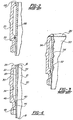
- the prior art piston sleeve 50 shown in Figure 3 has a substantially cylindrical surface 52 before a cylinder head 26 is clamped to the engine block 54.
- a wavy line 56 indicates the warpage (exaggerated) when the prior art sleeve 50 is clamped in place in a block 54.
- the piston rings 60 on a piston 62 are radially compressed springs that tend to expand and follow the contour of the inside surface 20 of a sleeve 10. If the inside surface is warped as shown by the wavy line 56 in Figure 3, a piston ring 60 is continuously expanding or contracting. This movement reduces the life of each ring 60 and wears the ring groove 64 in the piston 62. When the loaded piston sleeve 10 has a substantially cylindrical inside surface 20, the piston rings 60 have little change in diameter and wear is minimized.
- the unloaded piston sleeve 10 shown in Figure 6 has been machined so that the inside surface 20 will be substantially cylindrical when axially loaded and running at the expected operating temperature.
- the unloaded profile is obtained by determining the quantities of material to be removed or added to change the warped profile 56 to a straight line. Removing and adding material changes the strength of the piston sleeve 10 where material is removed or added The changes in strength requires modification of the final unloaded profile of the inner surface 20 of the piston sleeve 10.
- the operating temperature of a piston sleeve will vary along the length of the sleeve from the top surface 16 to the bottom surface 18. The operating temperature will also vary depending upon ambient temperature, engine load and fuel characteristics.
- the profile of an inner surface 20 of the piston sleeve 10 is also modified to correspond to the expected operating temperature of the sleeve in an internal combustion engine 12.
- the inner surface 20 of a piston sleeve 10 in an internal combustion engine 12 that is operating at the expected temperature and engine load is substantially cylindrical as shown in Figure 2. If there are changes in engine load, ambient temperature, or other operating conditions from the expected operating conditions, axial load on the piston sleeve 10 will change and the inner surface 20 will be slightly warped. However, large high compression engines 12 generally run in a relatively narrow temperature range. Expected changes in the inner surface 20 profile are generally small.
- a piston sleeve 10 manufactured as set forth above can be mounted in an engine 12 and the engine can be assembled without additional machining, honeing or polishing of the piston sleeve.
- the prior art piston sleeve 66 shown in Figure 2 has a cylindrical rim 68.
- This cylindrical rim 68 axially fixes the sleeve 66 in the block 70.
- the sleeve 66 expands and contracts axially with temperature changes.
- a seal 72 is provided to prevent leakage from the water jacket and accommodate axial movement of the sleeve 66 relative to the block 70.
- the seal 72 can accommodate the movement between the sleeve 66 and the block 70.
- seals 72 have a limited life.
- a diesel engine with a long life needs an improved sealing system as described above to eliminate the coolant leakage that may occur with seals 72 after a period of time.
Landscapes
- Engineering & Computer Science (AREA)
- Chemical & Material Sciences (AREA)
- Combustion & Propulsion (AREA)
- Mechanical Engineering (AREA)
- General Engineering & Computer Science (AREA)
- Pistons, Piston Rings, And Cylinders (AREA)
- Cylinder Crankcases Of Internal Combustion Engines (AREA)
- Compressors, Vaccum Pumps And Other Relevant Systems (AREA)
- Compressor (AREA)
- Reciprocating Pumps (AREA)
Applications Claiming Priority (3)
| Application Number | Priority Date | Filing Date | Title |
|---|---|---|---|
| US520111 | 2000-03-07 | ||
| US09/520,111 US6357400B1 (en) | 2000-03-07 | 2000-03-07 | Piston sleeve |
| PCT/US2001/007064 WO2001066928A1 (en) | 2000-03-07 | 2001-03-06 | Piston sleeve |
Publications (3)
| Publication Number | Publication Date |
|---|---|
| EP1264099A1 EP1264099A1 (en) | 2002-12-11 |
| EP1264099A4 EP1264099A4 (en) | 2004-07-07 |
| EP1264099B1 true EP1264099B1 (en) | 2006-07-19 |
Family
ID=24071246
Family Applications (1)
| Application Number | Title | Priority Date | Filing Date |
|---|---|---|---|
| EP01920214A Expired - Lifetime EP1264099B1 (en) | 2000-03-07 | 2001-03-06 | Piston sleeve |
Country Status (8)
| Country | Link |
|---|---|
| US (1) | US6357400B1 (pl) |
| EP (1) | EP1264099B1 (pl) |
| AU (1) | AU2001247290A1 (pl) |
| BR (1) | BR0109064A (pl) |
| DE (1) | DE60121552T2 (pl) |
| ES (1) | ES2269372T3 (pl) |
| PL (1) | PL357114A1 (pl) |
| WO (1) | WO2001066928A1 (pl) |
Families Citing this family (7)
| Publication number | Priority date | Publication date | Assignee | Title |
|---|---|---|---|---|
| US6675750B1 (en) * | 2002-04-25 | 2004-01-13 | Dana Corporation | Cylinder liner |
| JP4367288B2 (ja) * | 2004-08-17 | 2009-11-18 | トヨタ自動車株式会社 | エンジンのシリンダブロック |
| US8443768B2 (en) * | 2009-02-17 | 2013-05-21 | Mahle International Gmbh | High-flow cylinder liner cooling gallery |
| US8601995B2 (en) * | 2011-08-03 | 2013-12-10 | Cummins Intellectual Property, Inc. | Cylinder liner seal arrangement and method of providing the same |
| US20160252042A1 (en) * | 2015-02-27 | 2016-09-01 | Avl Powertrain Engineering, Inc. | Cylinder Liner |
| US9958358B2 (en) * | 2016-03-31 | 2018-05-01 | Caterpillar Inc. | Control system having seal damage counting |
| EP4077901B1 (en) | 2019-12-17 | 2025-12-10 | Cummins, Inc. | Profiled cylinder liner for bore distortion control |
Family Cites Families (19)
| Publication number | Priority date | Publication date | Assignee | Title |
|---|---|---|---|---|
| US2283424A (en) | 1939-03-20 | 1942-05-19 | Thompson Prod Inc | Cylinder liner sleeve |
| US2387971A (en) | 1942-01-14 | 1945-10-30 | Aspin Frank Metcalf | Cylinder liner and cylinder |
| US4127058A (en) | 1974-08-13 | 1978-11-28 | Mahle Gmbh | Liquid-cooled cylinder sleeves |
| FR2413553A1 (fr) | 1978-01-03 | 1979-07-27 | Renault | Chemise de moteur a combustion interne |
| US4244330A (en) | 1978-11-13 | 1981-01-13 | Cummins Engine Company, Inc. | Engine cylinder liner having a mid stop |
| US4399783A (en) | 1980-04-14 | 1983-08-23 | Deere & Company | Interference fit cylinder liner |
| US4385595A (en) | 1980-12-09 | 1983-05-31 | Cummins Engine Company, Inc. | Bottom stop cylinder liner and engine assembly |
| US4562799A (en) | 1983-01-17 | 1986-01-07 | Cummins Engine Company, Inc. | Monolithic ceramic cylinder liner and method of making same |
| US4905642A (en) | 1984-11-09 | 1990-03-06 | Honda Giken Kogyo Kabushiki Kaisha | Siamese-type cylinder block blank and apparatus for casting the same |
| US4926801A (en) | 1987-12-22 | 1990-05-22 | Mack Trucks, Inc. | Wet/dry cylinder liner for high output engines |
| US4986230A (en) | 1989-12-27 | 1991-01-22 | Ford Motor Company | Method of joining cylinder bore liners to an engine block |
| US5251579A (en) * | 1990-07-20 | 1993-10-12 | Ae Auto Parts Limited | Cylinder liners |
| FR2666628B1 (fr) | 1990-09-06 | 1994-09-16 | Melchior Jean | Dispositif d'etancheite entre la culasse et le cylindre d'une machine alternative a compression de fluide gazeux. |
| SE508983C2 (sv) | 1992-12-30 | 1998-11-23 | Scania Cv Ab | Vått cylinderfoder |
| US5575251A (en) | 1994-01-04 | 1996-11-19 | Caterpillar Inc. | Deck plate for an internal combustion engine |
| SE9503622L (sv) * | 1995-10-13 | 1996-09-23 | Scania Cv Ab | Anordning för avtätning av en förbränningsmotors förbränningsrum |
| US6116198A (en) * | 1997-07-21 | 2000-09-12 | Cummins Engine Company, Inc. | Replaceable cylinder liner with improved cooling |
| US5870990A (en) | 1997-09-02 | 1999-02-16 | Ford Global Technologies, Inc. | Cylinder bore liner for an internal combustion engine |
| US5979374A (en) * | 1998-06-12 | 1999-11-09 | Cummins Engine Company, Inc. | Control cooled cylinder liner |
-
2000
- 2000-03-07 US US09/520,111 patent/US6357400B1/en not_active Expired - Lifetime
-
2001
- 2001-03-06 AU AU2001247290A patent/AU2001247290A1/en not_active Abandoned
- 2001-03-06 WO PCT/US2001/007064 patent/WO2001066928A1/en not_active Ceased
- 2001-03-06 EP EP01920214A patent/EP1264099B1/en not_active Expired - Lifetime
- 2001-03-06 PL PL01357114A patent/PL357114A1/pl not_active Application Discontinuation
- 2001-03-06 ES ES01920214T patent/ES2269372T3/es not_active Expired - Lifetime
- 2001-03-06 DE DE60121552T patent/DE60121552T2/de not_active Expired - Fee Related
- 2001-03-06 BR BR0109064-0A patent/BR0109064A/pt active Search and Examination
Also Published As
| Publication number | Publication date |
|---|---|
| AU2001247290A1 (en) | 2001-09-17 |
| WO2001066928A1 (en) | 2001-09-13 |
| PL357114A1 (pl) | 2004-07-12 |
| ES2269372T3 (es) | 2007-04-01 |
| DE60121552T2 (de) | 2007-07-05 |
| EP1264099A4 (en) | 2004-07-07 |
| US6357400B1 (en) | 2002-03-19 |
| DE60121552D1 (de) | 2006-08-31 |
| BR0109064A (pt) | 2002-12-10 |
| EP1264099A1 (en) | 2002-12-11 |
Similar Documents
| Publication | Publication Date | Title |
|---|---|---|
| US6328001B1 (en) | Replaceable cylinder liner with improved cooling | |
| EP0731301B1 (en) | Seal device | |
| WO1998011365A9 (en) | Combustion gas seal for an internal combustion engine | |
| US20030151210A1 (en) | Metal gasket | |
| US3340774A (en) | Combination cylinder sleeve or liner and combustion chamber seal | |
| US10895218B2 (en) | Liner for engine cylinder with lower liner support | |
| WO1998011365A1 (en) | Combustion gas seal for an internal combustion engine | |
| US5979374A (en) | Control cooled cylinder liner | |
| US5582144A (en) | Dry cylinder liner for internal combustion engines | |
| EP1264099B1 (en) | Piston sleeve | |
| CN111396211A (zh) | 整体缸套与缸盖集成结构 | |
| SE508983C2 (sv) | Vått cylinderfoder | |
| US5380018A (en) | Piston ring having a non-uniform radial pressure distribution | |
| US5476076A (en) | Internal combustion piston engine utilizing interference movable fit technology | |
| CN111749808A (zh) | 组合式发动机 | |
| US5209197A (en) | Cylinder head/cylinder sealing device for a reciprocating pressurized gas machine | |
| KR20210135582A (ko) | 고온 작동을 위한 샤프트-실린더 어셈블리 | |
| JPH05187309A (ja) | 内燃機関のシリンダ構造 | |
| CN112901362B (zh) | 具有衬套捕捉部的发动机气缸衬套以及系统 | |
| EP1288464A2 (en) | Piston assembly for free piston internal combustion engine | |
| US6135008A (en) | Piston with lubricant-scraping ring and lubricant return ports | |
| US20020074733A1 (en) | Compression piston ring for use in internal combustion engine | |
| CN1207164A (zh) | 内燃机的燃气密封装置 | |
| HUT59470A (en) | Piston-ring unit for piston reciprocating machines particularly for internal combustion engines | |
| GB2364548A (en) | I.c. engine with replaceable cylinder liner |
Legal Events
| Date | Code | Title | Description |
|---|---|---|---|
| PUAI | Public reference made under article 153(3) epc to a published international application that has entered the european phase |
Free format text: ORIGINAL CODE: 0009012 |
|
| 17P | Request for examination filed |
Effective date: 20020823 |
|
| AK | Designated contracting states |
Kind code of ref document: A1 Designated state(s): AT BE CH CY DE DK ES FI FR GB GR IE IT LI LU MC NL PT SE TR |
|
| AX | Request for extension of the european patent |
Free format text: AL;LT;LV;MK;RO;SI |
|
| RBV | Designated contracting states (corrected) |
Designated state(s): AT BE CH CY DE ES FR GB IT LI |
|
| A4 | Supplementary search report drawn up and despatched |
Effective date: 20040526 |
|
| RIC1 | Information provided on ipc code assigned before grant |
Ipc: 7F 02F 1/10 A Ipc: 7F 02F 1/16 B |
|
| GRAP | Despatch of communication of intention to grant a patent |
Free format text: ORIGINAL CODE: EPIDOSNIGR1 |
|
| RBV | Designated contracting states (corrected) |
Designated state(s): DE ES FR GB IT |
|
| GRAS | Grant fee paid |
Free format text: ORIGINAL CODE: EPIDOSNIGR3 |
|
| GRAA | (expected) grant |
Free format text: ORIGINAL CODE: 0009210 |
|
| AK | Designated contracting states |
Kind code of ref document: B1 Designated state(s): DE ES FR GB IT |
|
| PG25 | Lapsed in a contracting state [announced via postgrant information from national office to epo] |
Ref country code: IT Free format text: LAPSE BECAUSE OF FAILURE TO SUBMIT A TRANSLATION OF THE DESCRIPTION OR TO PAY THE FEE WITHIN THE PRESCRIBED TIME-LIMIT;WARNING: LAPSES OF ITALIAN PATENTS WITH EFFECTIVE DATE BEFORE 2007 MAY HAVE OCCURRED AT ANY TIME BEFORE 2007. THE CORRECT EFFECTIVE DATE MAY BE DIFFERENT FROM THE ONE RECORDED. Effective date: 20060719 |
|
| REG | Reference to a national code |
Ref country code: GB Ref legal event code: FG4D |
|
| REF | Corresponds to: |
Ref document number: 60121552 Country of ref document: DE Date of ref document: 20060831 Kind code of ref document: P |
|
| ET | Fr: translation filed | ||
| REG | Reference to a national code |
Ref country code: ES Ref legal event code: FG2A Ref document number: 2269372 Country of ref document: ES Kind code of ref document: T3 |
|
| PLBE | No opposition filed within time limit |
Free format text: ORIGINAL CODE: 0009261 |
|
| STAA | Information on the status of an ep patent application or granted ep patent |
Free format text: STATUS: NO OPPOSITION FILED WITHIN TIME LIMIT |
|
| 26N | No opposition filed |
Effective date: 20070420 |
|
| PGFP | Annual fee paid to national office [announced via postgrant information from national office to epo] |
Ref country code: ES Payment date: 20090323 Year of fee payment: 9 |
|
| PGFP | Annual fee paid to national office [announced via postgrant information from national office to epo] |
Ref country code: GB Payment date: 20090206 Year of fee payment: 9 |
|
| PGFP | Annual fee paid to national office [announced via postgrant information from national office to epo] |
Ref country code: DE Payment date: 20090331 Year of fee payment: 9 Ref country code: IT Payment date: 20090319 Year of fee payment: 9 |
|
| PGFP | Annual fee paid to national office [announced via postgrant information from national office to epo] |
Ref country code: FR Payment date: 20090306 Year of fee payment: 9 |
|
| GBPC | Gb: european patent ceased through non-payment of renewal fee |
Effective date: 20100306 |
|
| REG | Reference to a national code |
Ref country code: FR Ref legal event code: ST Effective date: 20101130 |
|
| PG25 | Lapsed in a contracting state [announced via postgrant information from national office to epo] |
Ref country code: FR Free format text: LAPSE BECAUSE OF NON-PAYMENT OF DUE FEES Effective date: 20100331 |
|
| PG25 | Lapsed in a contracting state [announced via postgrant information from national office to epo] |
Ref country code: DE Free format text: LAPSE BECAUSE OF NON-PAYMENT OF DUE FEES Effective date: 20101001 |
|
| PG25 | Lapsed in a contracting state [announced via postgrant information from national office to epo] |
Ref country code: GB Free format text: LAPSE BECAUSE OF NON-PAYMENT OF DUE FEES Effective date: 20100306 Ref country code: IT Free format text: LAPSE BECAUSE OF NON-PAYMENT OF DUE FEES Effective date: 20100306 |
|
| REG | Reference to a national code |
Ref country code: ES Ref legal event code: FD2A Effective date: 20110415 |
|
| PG25 | Lapsed in a contracting state [announced via postgrant information from national office to epo] |
Ref country code: ES Free format text: LAPSE BECAUSE OF NON-PAYMENT OF DUE FEES Effective date: 20110404 |
|
| PG25 | Lapsed in a contracting state [announced via postgrant information from national office to epo] |
Ref country code: ES Free format text: LAPSE BECAUSE OF NON-PAYMENT OF DUE FEES Effective date: 20100307 |