EP1264115B1 - Accouplement d'un arbre - Google Patents
Accouplement d'un arbre Download PDFInfo
- Publication number
- EP1264115B1 EP1264115B1 EP01902908A EP01902908A EP1264115B1 EP 1264115 B1 EP1264115 B1 EP 1264115B1 EP 01902908 A EP01902908 A EP 01902908A EP 01902908 A EP01902908 A EP 01902908A EP 1264115 B1 EP1264115 B1 EP 1264115B1
- Authority
- EP
- European Patent Office
- Prior art keywords
- bellows
- variations
- segments
- drive shaft
- shaft coupling
- Prior art date
- Legal status (The legal status is an assumption and is not a legal conclusion. Google has not performed a legal analysis and makes no representation as to the accuracy of the status listed.)
- Expired - Lifetime
Links
- 238000010168 coupling process Methods 0.000 title claims abstract description 62
- 238000005859 coupling reaction Methods 0.000 title claims abstract description 62
- 230000008878 coupling Effects 0.000 title claims abstract description 61
- 239000002131 composite material Substances 0.000 claims abstract description 11
- 239000000835 fiber Substances 0.000 claims abstract description 9
- 239000000463 material Substances 0.000 claims abstract description 7
- 239000004593 Epoxy Substances 0.000 claims abstract description 5
- 239000000203 mixture Substances 0.000 claims abstract description 5
- 229920000049 Carbon (fiber) Polymers 0.000 claims abstract description 4
- 239000004917 carbon fiber Substances 0.000 claims abstract description 4
- 239000003365 glass fiber Substances 0.000 claims abstract description 4
- VNWKTOKETHGBQD-UHFFFAOYSA-N methane Chemical compound C VNWKTOKETHGBQD-UHFFFAOYSA-N 0.000 claims abstract description 4
- 229910000831 Steel Inorganic materials 0.000 claims description 3
- 239000010959 steel Substances 0.000 claims description 3
- 238000009434 installation Methods 0.000 abstract description 3
- 238000010276 construction Methods 0.000 abstract 2
- 239000000470 constituent Substances 0.000 abstract 1
- 238000005452 bending Methods 0.000 description 4
- 239000000446 fuel Substances 0.000 description 2
- 230000006978 adaptation Effects 0.000 description 1
- 230000005540 biological transmission Effects 0.000 description 1
- 230000006835 compression Effects 0.000 description 1
- 238000007906 compression Methods 0.000 description 1
- 230000000694 effects Effects 0.000 description 1
- 238000012986 modification Methods 0.000 description 1
- 230000004048 modification Effects 0.000 description 1
- WFKWXMTUELFFGS-UHFFFAOYSA-N tungsten Chemical compound [W] WFKWXMTUELFFGS-UHFFFAOYSA-N 0.000 description 1
- 239000010937 tungsten Substances 0.000 description 1
- 229910052721 tungsten Inorganic materials 0.000 description 1
Images

Classifications
-
- F—MECHANICAL ENGINEERING; LIGHTING; HEATING; WEAPONS; BLASTING
- F16—ENGINEERING ELEMENTS AND UNITS; GENERAL MEASURES FOR PRODUCING AND MAINTAINING EFFECTIVE FUNCTIONING OF MACHINES OR INSTALLATIONS; THERMAL INSULATION IN GENERAL
- F16D—COUPLINGS FOR TRANSMITTING ROTATION; CLUTCHES; BRAKES
- F16D3/00—Yielding couplings, i.e. with means permitting movement between the connected parts during the drive
- F16D3/50—Yielding couplings, i.e. with means permitting movement between the connected parts during the drive with the coupling parts connected by one or more intermediate members
- F16D3/72—Yielding couplings, i.e. with means permitting movement between the connected parts during the drive with the coupling parts connected by one or more intermediate members with axially-spaced attachments to the coupling parts
-
- F—MECHANICAL ENGINEERING; LIGHTING; HEATING; WEAPONS; BLASTING
- F16—ENGINEERING ELEMENTS AND UNITS; GENERAL MEASURES FOR PRODUCING AND MAINTAINING EFFECTIVE FUNCTIONING OF MACHINES OR INSTALLATIONS; THERMAL INSULATION IN GENERAL
- F16D—COUPLINGS FOR TRANSMITTING ROTATION; CLUTCHES; BRAKES
- F16D3/00—Yielding couplings, i.e. with means permitting movement between the connected parts during the drive
- F16D3/50—Yielding couplings, i.e. with means permitting movement between the connected parts during the drive with the coupling parts connected by one or more intermediate members
- F16D3/72—Yielding couplings, i.e. with means permitting movement between the connected parts during the drive with the coupling parts connected by one or more intermediate members with axially-spaced attachments to the coupling parts
- F16D3/725—Yielding couplings, i.e. with means permitting movement between the connected parts during the drive with the coupling parts connected by one or more intermediate members with axially-spaced attachments to the coupling parts with an intermediate member made of fibre-reinforced resin
Definitions
- the present invention relates to a drive shaft coupling for transfer of torsional force between a shaft and a rotatable element, which drive shaft coupling comprises a rigid tube section and a flexible coupling member connected to the tube section, with at least two in series connected bellows segments, enabling center axis deviations between the shaft and the rotatable element.
- US 5,725,434 discloses a shaft of composite material with an integrate, elastically deformable coupling flange enabling center axis deviations at the mounting end of the shaft.
- a problem with this known drive shaft coupling is that it is comparatively bulky, as the coupling flange is radially large.
- US 4,173,128 disclose a shaft laminated of composite material with flexible coupling sections adjacent the ends of the shaft. These flexible-coupling sections comprise in series coupled bellows with identical geometry and elasticity for bending. The need for space is reduced radially by using in series coupled bellows. However, it has turned out that this type of drive shaft coupling is less suitable for uses where the center axis deviations between bellows is comparatively large and high torque occur.
- US 3,707,082 discloses a shaft coupling comprising a ball-and-socket joint and a coupling muff, where bellow segments with a smaller flexibility than other bellow segments in the coupling muff have been arranged in a symmetrical way at both ends of the muff.
- This has the effect of distributing the axially extreme bending stresses over a larger area and eliminating the tendency for initial failure in the area of the first convolution, that is, a local stress phenomenon is described at the ends of the muff.
- This stress phenomenon is due to that the ball-and-socket joint is arranged symmetrically, which results in a simultaneous compression and extension in an axial direction at the inside and outside of the muff respectively.
- the angling of this shaft coupling is strongly geometrically controlled due to the ball-and-socket joint, giving rise to said unwanted local stress phenomenon.
- one object of the invention is to provide a drive shaft coupling with a small need of space, which also copes with large angle movements as well as high torsion.
- the drive shaft coupling according to the invention is characterized in that several adjacent bellows segments present different flexural resistance, wherein the bellows segment nearest the tube section presents less flexural resistance than the immediate following bellows segment, and where the bellows segment farthest away from the tube section presents the highest flexural resistance in the shaft coupling.
- each individual bellows segment may be dimensioned in such a way that stress is distributed evenly over all bellows segments so that the component may be optimized, e.g. with reference to installation and strength.
- Another improvement versus conventional universal joint shafts is the increased freedom for installation of the driveline.
- a shaft designed according to the invention does not need to have equal angle of articulation in the bellows as a universal joint shaft has in the universal joints.
- the variations in flexural resistance between two adjacent bellows segments may be produced by variations in the thickness of material of the bellows segments.
- these variations may be produced by variations in the outside diameter of the bellows segments.
- the variations in flexural resistance between two adjacent bellows segments are produced by variations in the inside diameter of the bellows segments.
- these variations may be produced by variation of the radial angles of each bellows diaphragm in relation to the longitudinal axis of the coupling member.
- the variations in flexural resistance between in series connected bellows segments are produced by variation of the distance between adjacently positioned bellows segments.
- the coupling member is manufactured from an epoxy composite with a mixture of glass fiber and carbon fiber.
- the variations in flexural resistance between two adjacent bellows segments can then be produced by variation of the fiber direction in the composite material.
- the tube section and the coupling member may be manufactured in one piece from steel.
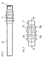
- the drive shaft coupling shown in Fig. 1 is intended to be used as a universal joint shaft on an vehicle and comprises a stiff tube section 10 and a coupling member 11.
- the drive shaft coupling preferably comprises mirror-inverted arranged coupling members 11, in the respective end of the tube section 10, but for any other field of use, it would be possible to use only a single coupling member 11.
- An end piece 12 is mounted at the free end of the coupling member, for connection to a not shown rotor, e.g. a differential gear at the rear axle of a vehicle.
- a not shown rotor e.g. a differential gear at the rear axle of a vehicle.
- the coupling member 11 is provided with four in series interlinked bellows segments 13a, 13b, 13c and 13d (see Fig. 2 ).
- the bellows segments 13 are individually designed, so that they exhibit different flexural resistance.
- the bellows segment 13a nearest the tube section 10 exhibits a lower flexural resistance than the immediate following bellows segment 13b.
- the bellows segment 13b exhibits a lower flexural resistance than the immediate following bellows segment 13c
- the bellows segment 13c a lower flexural resistance than the immediate following bellows segment 13d.
- the bellows segment located closest to the point of attachment i.e. the end piece 1
- the bellows segment located closest to the point of attachment i.e. the end piece 1
- the bending load and the deformation due to stress of the tube section will be distributed equally between the different bellows segments due to the above-described design of the coupling member 11.
- the variations in flexural resistance have been produced foremost by two measures.
- the different bellows segments have been given different outer diameter, in such a way that the bellows segments 13a closest to the tube section 10 has a larger outer diameter D than the immediate following bellows segment 13b.
- the bellows segment 13b exhibits a larger outer diameter than the immediate following bellows segment 13c, and the bellows segment 13c has a larger outer diameter than the next following bellows segment 13d.
- a reduced outer diameter provides increased flexural resistance in the bellows segment and vice versa.
- the variations in flexural resistance between two adjacent bellows segments have been produced by variation of the radial angles ⁇ of the bellows diaphragm in relation to the longitudinal axis of the coupling member.
- the diaphragm sides of the bellows segment 13a immediate the tube section 10 exhibits a more blunts angle ⁇ towards the longitudinal axis 14 of the coupling member than the diaphragm sides of the next following bellows segment 13b.
- the diaphragm sides of the bellows segments 13d accordingly exhibits the most pointed angle towards the longitudinal axis 14 of the coupling member. In this case, a more pointed angle ⁇ results in more flexural resistance in the bellows segments and vice versa.
- the distances L1 and L2 will usually differ.
- the flexural resistance may be varied by altering the material thickness in the bellows, so that an increased thickness of material results in increasing flexural resistance in the bellows segment and vice versa.
- the flexural resistance may be varied by altering the inner diameter d of the bellows, in such a way that a reduction of the inner diameter produces a reduced flexural resistance and vice versa.
- a drive shaft coupling produced from an epoxy composite with a fiber mat may be varied with regard to the orientation of the fiber mats with reference to the longitudinal axis 14 of the drive shaft coupling, so that specific different flexural resistance are produced in the respective bellows segments.
- the composition of the composite material may be varied between different bellows segments in the coupling member; e.g. so that different flexural resistance is produced by variation of the large quantity proportions epoxy/fiber.
- Glass fiber, carbon fiber, KEVLAR-fiber and tungsten fiber may be mentioned as example of suitable fiber for the coupling member.
- the drive shaft coupling according to the invention may also be produced from suitable tube steel, wherein the last mentioned variants for producing variation in flexural resistance are omitted.
Landscapes
- Engineering & Computer Science (AREA)
- General Engineering & Computer Science (AREA)
- Mechanical Engineering (AREA)
- Shafts, Cranks, Connecting Bars, And Related Bearings (AREA)
- Diaphragms And Bellows (AREA)
- Moulding By Coating Moulds (AREA)
- Valve Device For Special Equipments (AREA)
- Mechanical Operated Clutches (AREA)
- Motor Power Transmission Devices (AREA)
Claims (10)
- Accouplement d'arbre d'entraînement pour transférer une force de torsion entre un arbre et un élément rotatif, lequel accouplement d'arbre d'entraînement comprend un tronçon de tube rigide (10) et un élément d'accouplement souple (11) relié au tronçon de tube (10) avec au moins deux segments de soufflet reliés en série (13a à 13b), permettant des écarts d'axe central entre l'arbre et l'élément rotatif,
caractérisé en ce que
plusieurs segments de soufflet adjacents présentent une résistance à la flexion différente, le segment de soufflet (13a) situé le plus proche du tronçon de tube (10) présente une plus faible résistance à la flexion que le segment de soufflet immédiatement suivant (13b), et où le segment de soufflet (13d) le plus loin du tronçon de tube (10) présente la résistance à la flexion la plus élevée dans l'accouplement d'arbre. - Accouplement d'arbre d'entraînement selon la revendication 1,
caractérisé en ce que
les variations de résistance à la flexion entre deux segments de soufflet adjacents sont produites par des variations d'épaisseur de matériau des segments de soufflet. - Accouplement d'arbre d'entraînement selon la revendication 1 ou 2,
caractérisé en ce que
les variations de résistance à la flexion entre deux segments de soufflet adjacents sont produites par des variations du diamètre extérieur (D) des segments de soufflet. - Accouplement d'arbre d'entraînement selon l'une quelconque des revendications 1 à 3,
caractérisé en ce que
les variations de résistance à la flexion entre deux segments de soufflet adjacents sont produites par des variations du diamètre intérieur (d) des segments de soufflet. - Accouplement d'arbre d'entraînement selon l'une quelconque des revendications 1 à 4,
caractérisé en ce que
les variations de résistance à la flexion entre deux segments de soufflet adjacents sont produites par une variation des angles radiaux (α) de chaque membrane de soufflet par rapport à l'axe longitudinal (14) de l'élément d'accouplement (11). - Accouplement d'arbre d'entraînement selon l'une quelconque des revendications 1 à 5,
caractérisé en ce que
les variations de résistance à la flexion entre des segments de soufflet reliés en série sont produites par une variation de la distance entre des segments de soufflet positionnés de manière adjacente. - Accouplement d'arbre d'entraînement selon l'une quelconque des revendications 1 à 6,
caractérisé en ce que
l'élément d'accouplement est fabriqué à partir d'un composite d'époxy avec un mélange de fibre de verre et de fibre de carbone. - Accouplement d'arbre d'entraînement selon la revendication 7,
caractérisé en ce que
les variations de résistance à la flexion entre deux segments de soufflet adjacents sont produites par une variation de la direction des fibres dans le matériau composite. - Accouplement d'arbre d'entraînement selon l'une quelconque des revendications 1 à 8, caractérisé en ce que le tronçon de tube et l'élément d'accouplement sont fabriqués en une seule pièce.
- Accouplement d'arbre d'entraînement selon l'une quelconque des revendications 1 à 6, caractérisé en ce que le tronçon de tube et l'élément d'accouplement sont fabriqués en une pièce d'acier.
Applications Claiming Priority (3)
| Application Number | Priority Date | Filing Date | Title |
|---|---|---|---|
| SE0000816A SE517177C2 (sv) | 2000-03-09 | 2000-03-09 | Axelkoppling |
| SE0000816 | 2000-03-09 | ||
| PCT/SE2001/000143 WO2001066965A1 (fr) | 2000-03-09 | 2001-01-25 | Accouplement d'un arbre |
Publications (2)
| Publication Number | Publication Date |
|---|---|
| EP1264115A1 EP1264115A1 (fr) | 2002-12-11 |
| EP1264115B1 true EP1264115B1 (fr) | 2009-03-18 |
Family
ID=20278780
Family Applications (1)
| Application Number | Title | Priority Date | Filing Date |
|---|---|---|---|
| EP01902908A Expired - Lifetime EP1264115B1 (fr) | 2000-03-09 | 2001-01-25 | Accouplement d'un arbre |
Country Status (8)
| Country | Link |
|---|---|
| US (1) | US6695705B2 (fr) |
| EP (1) | EP1264115B1 (fr) |
| AT (1) | ATE426105T1 (fr) |
| AU (1) | AU2001230672A1 (fr) |
| BR (1) | BR0108986B1 (fr) |
| DE (1) | DE60138011D1 (fr) |
| SE (1) | SE517177C2 (fr) |
| WO (1) | WO2001066965A1 (fr) |
Families Citing this family (19)
| Publication number | Priority date | Publication date | Assignee | Title |
|---|---|---|---|---|
| US20060009297A1 (en) * | 2004-07-08 | 2006-01-12 | Hubiak William R | Flexible coupling having a center with opposing re-entrant folds |
| US20060094514A1 (en) * | 2004-10-29 | 2006-05-04 | Eastman Kodak Company | Flexible coupling |
| US20060094513A1 (en) * | 2004-10-29 | 2006-05-04 | Eastman Kodak Company | Coupling apparatus |
| US7275332B2 (en) * | 2005-02-22 | 2007-10-02 | Carestream Health, Inc. | Multi-axis positioning apparatus |
| EP1994632A1 (fr) * | 2007-03-14 | 2008-11-26 | Zenergy Power GmbH | Moyen de transmission de couple pour relier de manière solidaire en rotation un arbre et un rotor |
| EP2150710A4 (fr) * | 2007-04-06 | 2011-05-04 | Lawrie Technology Inc | Arbre de transmission composite flexible à densité de couple élevée |
| US7780927B2 (en) * | 2008-02-20 | 2010-08-24 | Richard A Holl | Spinning tube in tube reactors and their methods of operation |
| US8147194B2 (en) * | 2008-11-06 | 2012-04-03 | Honeywell International Inc. | Turbine engine components |
| DE102009009108B3 (de) * | 2009-02-16 | 2010-06-17 | Bayer Technology Services Gmbh | Verfahren und Vorrichtung zum Verbinden eines flexiblen profilierten Hohlzylinders mit einem zylinderförmigen Körper, sowie danach hergestellte Bestrahlungsmodule |
| KR101499218B1 (ko) | 2013-08-29 | 2015-03-05 | 현대자동차주식회사 | 저진동 특성을 가지는 자동차용 인터쿨러 파이프 |
| GB2571714A (en) * | 2018-03-05 | 2019-09-11 | Lentus Composites Ltd | Drive shaft and method and apparatus suitable for use in the manufacture thereof |
| DE102018119977A1 (de) | 2018-08-16 | 2020-02-20 | Thyssenkrupp Ag | Lenkgetriebe für ein Steer-by-Wire-Lenksystem |
| DE102018120266A1 (de) | 2018-08-21 | 2020-02-27 | Thyssenkrupp Ag | Steer-by-Wire-Lenkgetriebe mit Hohlwellenmotor und Kugelgewindetrieb |
| US12253107B2 (en) | 2019-01-15 | 2025-03-18 | Hamilton Sundstrand Corporation | Drive shafts with enhanced bending flexibility |
| US11486439B2 (en) | 2019-02-18 | 2022-11-01 | Hamilton Sundstrand Corporation | Drive shaft with non-cylindrical shape |
| US11273610B2 (en) | 2019-03-21 | 2022-03-15 | Goodrich Corporation | Manufacturing methods for composite driveshafts |
| US11260605B2 (en) | 2020-01-21 | 2022-03-01 | Goodrich Corporation | Flexible thermoplastic composite coupling and method of manufacture |
| US11725531B2 (en) * | 2021-11-22 | 2023-08-15 | Raytheon Technologies Corporation | Bore compartment seals for gas turbine engines |
| US12467499B2 (en) | 2022-08-22 | 2025-11-11 | Hamilton Sundstrand Corporation | Drive shaft with non-cylindrical shape and spaced reinforcements |
Family Cites Families (9)
| Publication number | Priority date | Publication date | Assignee | Title |
|---|---|---|---|---|
| US1658750A (en) * | 1926-09-30 | 1928-02-07 | Pneumatic Appliances Corp | Universal joint |
| US2848882A (en) * | 1955-11-25 | 1958-08-26 | Gen Motors Corp | Drive noise insulating means |
| US3623339A (en) * | 1969-11-28 | 1971-11-30 | Ford Motor Co | Bellows flexible joint |
| US3707082A (en) * | 1970-09-22 | 1972-12-26 | Ford Motor Co | Bellows flexible joint |
| US4173128A (en) * | 1978-05-23 | 1979-11-06 | Grumman Aerospace Corporation | Composite drive shaft |
| US4512209A (en) * | 1983-03-18 | 1985-04-23 | The Torrington Company | Steering column |
| US4713128A (en) * | 1984-09-27 | 1987-12-15 | Daniel Kerwin | Machine and method for applying miniaturized indicia to articles |
| US5725434A (en) | 1994-11-28 | 1998-03-10 | Deutsche Forschungsanstalt Fur Luft-Un Raumfahrt E. V. | Shaft of fibre-reinforced material |
| JP2000283139A (ja) * | 1999-03-30 | 2000-10-13 | Fuji Heavy Ind Ltd | 車両用プロペラシャフト |
-
2000
- 2000-03-09 SE SE0000816A patent/SE517177C2/sv not_active IP Right Cessation
-
2001
- 2001-01-25 DE DE60138011T patent/DE60138011D1/de not_active Expired - Lifetime
- 2001-01-25 AT AT01902908T patent/ATE426105T1/de not_active IP Right Cessation
- 2001-01-25 WO PCT/SE2001/000143 patent/WO2001066965A1/fr not_active Ceased
- 2001-01-25 AU AU2001230672A patent/AU2001230672A1/en not_active Abandoned
- 2001-01-25 BR BRPI0108986-2A patent/BR0108986B1/pt not_active IP Right Cessation
- 2001-01-25 EP EP01902908A patent/EP1264115B1/fr not_active Expired - Lifetime
-
2002
- 2002-09-09 US US10/065,009 patent/US6695705B2/en not_active Expired - Lifetime
Also Published As
| Publication number | Publication date |
|---|---|
| SE0000816L (sv) | 2001-09-10 |
| SE0000816D0 (sv) | 2000-03-09 |
| BR0108986A (pt) | 2003-06-03 |
| SE517177C2 (sv) | 2002-04-23 |
| EP1264115A1 (fr) | 2002-12-11 |
| US20020198057A1 (en) | 2002-12-26 |
| AU2001230672A1 (en) | 2001-09-17 |
| US6695705B2 (en) | 2004-02-24 |
| BR0108986B1 (pt) | 2010-11-16 |
| ATE426105T1 (de) | 2009-04-15 |
| DE60138011D1 (de) | 2009-04-30 |
| WO2001066965A1 (fr) | 2001-09-13 |
Similar Documents
| Publication | Publication Date | Title |
|---|---|---|
| US6695705B2 (en) | Shaft coupling | |
| US4540385A (en) | Drive shaft assembly | |
| US5221232A (en) | Flexible disc-like coupling element | |
| EP0788586B1 (fr) | Raccord entre deux composants | |
| US5158504A (en) | Flexible coupling including a flexible diaphragm element contoured with its thinnest thickness near the center thereof | |
| US6364611B1 (en) | Helicopter power transmitting apparatus | |
| US3292389A (en) | Vibration-damped drive shaft | |
| US3623339A (en) | Bellows flexible joint | |
| WO2008002845A2 (fr) | Couplage à torsion à taux multiples | |
| US4758204A (en) | Transmission system | |
| US4187699A (en) | Universal joint for connecting shafts | |
| EP0636805A1 (fr) | Accouplement d'arbres | |
| KR102039819B1 (ko) | 가요성 조인트 커플러 | |
| US7445555B2 (en) | Axial insulation for a universal joint | |
| GB2065269A (en) | Torque transmission couplings | |
| US7922593B2 (en) | Driveshaft assembly | |
| JP2958894B2 (ja) | 動力伝達軸 | |
| US7775889B2 (en) | Universal cross joint with axial insulation | |
| CN223411237U (zh) | 传动轴以及车辆 | |
| JP2005009615A (ja) | 動力伝達部材のスプライン嵌合構造 | |
| GB2082717A (en) | Improvements in or relating to link couplings | |
| EP1733608B1 (fr) | Entraînement final de roue pour véhicule agricole | |
| CN115280030A (zh) | 用于将两个轴以错位补偿的方式连接起来的能运动的双联轴器 | |
| US7878912B2 (en) | Cardanic cross joint with insulation | |
| US20020016207A1 (en) | Torsionally elastic coupling |
Legal Events
| Date | Code | Title | Description |
|---|---|---|---|
| PUAI | Public reference made under article 153(3) epc to a published international application that has entered the european phase |
Free format text: ORIGINAL CODE: 0009012 |
|
| 17P | Request for examination filed |
Effective date: 20021009 |
|
| AK | Designated contracting states |
Kind code of ref document: A1 Designated state(s): AT BE CH CY DE DK ES FI FR GB GR IE IT LI LU MC NL PT SE TR |
|
| AX | Request for extension of the european patent |
Free format text: AL;LT;LV;MK;RO;SI |
|
| 17Q | First examination report despatched |
Effective date: 20080618 |
|
| GRAP | Despatch of communication of intention to grant a patent |
Free format text: ORIGINAL CODE: EPIDOSNIGR1 |
|
| GRAP | Despatch of communication of intention to grant a patent |
Free format text: ORIGINAL CODE: EPIDOSNIGR1 |
|
| GRAS | Grant fee paid |
Free format text: ORIGINAL CODE: EPIDOSNIGR3 |
|
| GRAA | (expected) grant |
Free format text: ORIGINAL CODE: 0009210 |
|
| AK | Designated contracting states |
Kind code of ref document: B1 Designated state(s): AT BE CH CY DE DK ES FI FR GB GR IE IT LI LU MC NL PT SE TR |
|
| REG | Reference to a national code |
Ref country code: GB Ref legal event code: FG4D |
|
| REG | Reference to a national code |
Ref country code: CH Ref legal event code: EP |
|
| REG | Reference to a national code |
Ref country code: IE Ref legal event code: FG4D |
|
| REF | Corresponds to: |
Ref document number: 60138011 Country of ref document: DE Date of ref document: 20090430 Kind code of ref document: P |
|
| PG25 | Lapsed in a contracting state [announced via postgrant information from national office to epo] |
Ref country code: NL Free format text: LAPSE BECAUSE OF FAILURE TO SUBMIT A TRANSLATION OF THE DESCRIPTION OR TO PAY THE FEE WITHIN THE PRESCRIBED TIME-LIMIT Effective date: 20090318 Ref country code: FI Free format text: LAPSE BECAUSE OF FAILURE TO SUBMIT A TRANSLATION OF THE DESCRIPTION OR TO PAY THE FEE WITHIN THE PRESCRIBED TIME-LIMIT Effective date: 20090318 |
|
| PG25 | Lapsed in a contracting state [announced via postgrant information from national office to epo] |
Ref country code: SE Free format text: LAPSE BECAUSE OF FAILURE TO SUBMIT A TRANSLATION OF THE DESCRIPTION OR TO PAY THE FEE WITHIN THE PRESCRIBED TIME-LIMIT Effective date: 20090618 Ref country code: AT Free format text: LAPSE BECAUSE OF FAILURE TO SUBMIT A TRANSLATION OF THE DESCRIPTION OR TO PAY THE FEE WITHIN THE PRESCRIBED TIME-LIMIT Effective date: 20090318 |
|
| NLV1 | Nl: lapsed or annulled due to failure to fulfill the requirements of art. 29p and 29m of the patents act | ||
| PG25 | Lapsed in a contracting state [announced via postgrant information from national office to epo] |
Ref country code: BE Free format text: LAPSE BECAUSE OF FAILURE TO SUBMIT A TRANSLATION OF THE DESCRIPTION OR TO PAY THE FEE WITHIN THE PRESCRIBED TIME-LIMIT Effective date: 20090318 |
|
| PG25 | Lapsed in a contracting state [announced via postgrant information from national office to epo] |
Ref country code: ES Free format text: LAPSE BECAUSE OF FAILURE TO SUBMIT A TRANSLATION OF THE DESCRIPTION OR TO PAY THE FEE WITHIN THE PRESCRIBED TIME-LIMIT Effective date: 20090629 Ref country code: PT Free format text: LAPSE BECAUSE OF FAILURE TO SUBMIT A TRANSLATION OF THE DESCRIPTION OR TO PAY THE FEE WITHIN THE PRESCRIBED TIME-LIMIT Effective date: 20090826 |
|
| PLBE | No opposition filed within time limit |
Free format text: ORIGINAL CODE: 0009261 |
|
| STAA | Information on the status of an ep patent application or granted ep patent |
Free format text: STATUS: NO OPPOSITION FILED WITHIN TIME LIMIT |
|
| PG25 | Lapsed in a contracting state [announced via postgrant information from national office to epo] |
Ref country code: DK Free format text: LAPSE BECAUSE OF FAILURE TO SUBMIT A TRANSLATION OF THE DESCRIPTION OR TO PAY THE FEE WITHIN THE PRESCRIBED TIME-LIMIT Effective date: 20090318 |
|
| 26N | No opposition filed |
Effective date: 20091221 |
|
| PG25 | Lapsed in a contracting state [announced via postgrant information from national office to epo] |
Ref country code: MC Free format text: LAPSE BECAUSE OF NON-PAYMENT OF DUE FEES Effective date: 20100131 |
|
| REG | Reference to a national code |
Ref country code: CH Ref legal event code: PL |
|
| GBPC | Gb: european patent ceased through non-payment of renewal fee |
Effective date: 20100125 |
|
| REG | Reference to a national code |
Ref country code: FR Ref legal event code: ST Effective date: 20100930 |
|
| REG | Reference to a national code |
Ref country code: IE Ref legal event code: MM4A |
|
| PG25 | Lapsed in a contracting state [announced via postgrant information from national office to epo] |
Ref country code: CH Free format text: LAPSE BECAUSE OF NON-PAYMENT OF DUE FEES Effective date: 20100131 Ref country code: FR Free format text: LAPSE BECAUSE OF NON-PAYMENT OF DUE FEES Effective date: 20100201 Ref country code: GR Free format text: LAPSE BECAUSE OF FAILURE TO SUBMIT A TRANSLATION OF THE DESCRIPTION OR TO PAY THE FEE WITHIN THE PRESCRIBED TIME-LIMIT Effective date: 20090619 Ref country code: LI Free format text: LAPSE BECAUSE OF NON-PAYMENT OF DUE FEES Effective date: 20100131 |
|
| PG25 | Lapsed in a contracting state [announced via postgrant information from national office to epo] |
Ref country code: GB Free format text: LAPSE BECAUSE OF NON-PAYMENT OF DUE FEES Effective date: 20100125 |
|
| PG25 | Lapsed in a contracting state [announced via postgrant information from national office to epo] |
Ref country code: IE Free format text: LAPSE BECAUSE OF NON-PAYMENT OF DUE FEES Effective date: 20100125 |
|
| PG25 | Lapsed in a contracting state [announced via postgrant information from national office to epo] |
Ref country code: IT Free format text: LAPSE BECAUSE OF FAILURE TO SUBMIT A TRANSLATION OF THE DESCRIPTION OR TO PAY THE FEE WITHIN THE PRESCRIBED TIME-LIMIT Effective date: 20090318 |
|
| PG25 | Lapsed in a contracting state [announced via postgrant information from national office to epo] |
Ref country code: CY Free format text: LAPSE BECAUSE OF FAILURE TO SUBMIT A TRANSLATION OF THE DESCRIPTION OR TO PAY THE FEE WITHIN THE PRESCRIBED TIME-LIMIT Effective date: 20090318 |
|
| PG25 | Lapsed in a contracting state [announced via postgrant information from national office to epo] |
Ref country code: LU Free format text: LAPSE BECAUSE OF NON-PAYMENT OF DUE FEES Effective date: 20100125 |
|
| PG25 | Lapsed in a contracting state [announced via postgrant information from national office to epo] |
Ref country code: TR Free format text: LAPSE BECAUSE OF FAILURE TO SUBMIT A TRANSLATION OF THE DESCRIPTION OR TO PAY THE FEE WITHIN THE PRESCRIBED TIME-LIMIT Effective date: 20090318 |
|
| PGFP | Annual fee paid to national office [announced via postgrant information from national office to epo] |
Ref country code: DE Payment date: 20200131 Year of fee payment: 20 |
|
| REG | Reference to a national code |
Ref country code: DE Ref legal event code: R071 Ref document number: 60138011 Country of ref document: DE |