EP1264204B1 - Faserkoppler, system und zugehörige verfahren zur reduktion von rückreflektionen - Google Patents
Faserkoppler, system und zugehörige verfahren zur reduktion von rückreflektionen Download PDFInfo
- Publication number
- EP1264204B1 EP1264204B1 EP01952595A EP01952595A EP1264204B1 EP 1264204 B1 EP1264204 B1 EP 1264204B1 EP 01952595 A EP01952595 A EP 01952595A EP 01952595 A EP01952595 A EP 01952595A EP 1264204 B1 EP1264204 B1 EP 1264204B1
- Authority
- EP
- European Patent Office
- Prior art keywords
- light
- light source
- optical element
- optical
- fibre
- Prior art date
- Legal status (The legal status is an assumption and is not a legal conclusion. Google has not performed a legal analysis and makes no representation as to the accuracy of the status listed.)
- Expired - Lifetime
Links
- 239000000835 fiber Substances 0.000 title claims description 59
- 238000000034 method Methods 0.000 title description 2
- 230000003287 optical effect Effects 0.000 claims abstract description 54
- 239000013307 optical fiber Substances 0.000 claims description 16
- 230000008878 coupling Effects 0.000 claims description 8
- 238000010168 coupling process Methods 0.000 claims description 8
- 238000005859 coupling reaction Methods 0.000 claims description 8
- 230000008859 change Effects 0.000 claims description 5
- 239000000758 substrate Substances 0.000 description 6
- 230000005540 biological transmission Effects 0.000 description 4
- 238000013507 mapping Methods 0.000 description 4
- 238000013461 design Methods 0.000 description 3
- 230000009467 reduction Effects 0.000 description 3
- 230000004075 alteration Effects 0.000 description 2
- 238000012986 modification Methods 0.000 description 2
- 230000004048 modification Effects 0.000 description 2
- 238000004891 communication Methods 0.000 description 1
- 239000006185 dispersion Substances 0.000 description 1
- 230000000694 effects Effects 0.000 description 1
- 239000011521 glass Substances 0.000 description 1
- 238000003384 imaging method Methods 0.000 description 1
- 230000010354 integration Effects 0.000 description 1
- 238000002955 isolation Methods 0.000 description 1
- 230000010287 polarization Effects 0.000 description 1
- 230000001902 propagating effect Effects 0.000 description 1
- 230000000717 retained effect Effects 0.000 description 1
- 239000004065 semiconductor Substances 0.000 description 1
- 238000000926 separation method Methods 0.000 description 1
- 238000007493 shaping process Methods 0.000 description 1
- 125000006850 spacer group Chemical group 0.000 description 1
- 230000003595 spectral effect Effects 0.000 description 1
- 230000001629 suppression Effects 0.000 description 1
Images


Classifications
-
- G—PHYSICS
- G02—OPTICS
- G02B—OPTICAL ELEMENTS, SYSTEMS OR APPARATUS
- G02B6/00—Light guides; Structural details of arrangements comprising light guides and other optical elements, e.g. couplings
- G02B6/24—Coupling light guides
- G02B6/42—Coupling light guides with opto-electronic elements
- G02B6/4201—Packages, e.g. shape, construction, internal or external details
- G02B6/4204—Packages, e.g. shape, construction, internal or external details the coupling comprising intermediate optical elements, e.g. lenses, holograms
-
- G—PHYSICS
- G02—OPTICS
- G02B—OPTICAL ELEMENTS, SYSTEMS OR APPARATUS
- G02B19/00—Condensers, e.g. light collectors or similar non-imaging optics
- G02B19/0004—Condensers, e.g. light collectors or similar non-imaging optics characterised by the optical means employed
- G02B19/0028—Condensers, e.g. light collectors or similar non-imaging optics characterised by the optical means employed refractive and reflective surfaces, e.g. non-imaging catadioptric systems
-
- G—PHYSICS
- G02—OPTICS
- G02B—OPTICAL ELEMENTS, SYSTEMS OR APPARATUS
- G02B19/00—Condensers, e.g. light collectors or similar non-imaging optics
- G02B19/0033—Condensers, e.g. light collectors or similar non-imaging optics characterised by the use
- G02B19/0047—Condensers, e.g. light collectors or similar non-imaging optics characterised by the use for use with a light source
- G02B19/0052—Condensers, e.g. light collectors or similar non-imaging optics characterised by the use for use with a light source the light source comprising a laser diode
-
- G—PHYSICS
- G02—OPTICS
- G02B—OPTICAL ELEMENTS, SYSTEMS OR APPARATUS
- G02B27/00—Optical systems or apparatus not provided for by any of the groups G02B1/00 - G02B26/00, G02B30/00
- G02B27/42—Diffraction optics, i.e. systems including a diffractive element being designed for providing a diffractive effect
-
- G—PHYSICS
- G02—OPTICS
- G02B—OPTICAL ELEMENTS, SYSTEMS OR APPARATUS
- G02B27/00—Optical systems or apparatus not provided for by any of the groups G02B1/00 - G02B26/00, G02B30/00
- G02B27/42—Diffraction optics, i.e. systems including a diffractive element being designed for providing a diffractive effect
- G02B27/4233—Diffraction optics, i.e. systems including a diffractive element being designed for providing a diffractive effect having a diffractive element [DOE] contributing to a non-imaging application
- G02B27/4255—Diffraction optics, i.e. systems including a diffractive element being designed for providing a diffractive effect having a diffractive element [DOE] contributing to a non-imaging application for alignment or positioning purposes
-
- G—PHYSICS
- G02—OPTICS
- G02B—OPTICAL ELEMENTS, SYSTEMS OR APPARATUS
- G02B27/00—Optical systems or apparatus not provided for by any of the groups G02B1/00 - G02B26/00, G02B30/00
- G02B27/42—Diffraction optics, i.e. systems including a diffractive element being designed for providing a diffractive effect
- G02B27/4272—Diffraction optics, i.e. systems including a diffractive element being designed for providing a diffractive effect having plural diffractive elements positioned sequentially along the optical path
-
- G—PHYSICS
- G02—OPTICS
- G02B—OPTICAL ELEMENTS, SYSTEMS OR APPARATUS
- G02B6/00—Light guides; Structural details of arrangements comprising light guides and other optical elements, e.g. couplings
- G02B6/24—Coupling light guides
- G02B6/26—Optical coupling means
- G02B6/28—Optical coupling means having data bus means, i.e. plural waveguides interconnected and providing an inherently bidirectional system by mixing and splitting signals
- G02B6/293—Optical coupling means having data bus means, i.e. plural waveguides interconnected and providing an inherently bidirectional system by mixing and splitting signals with wavelength selective means
- G02B6/29304—Optical coupling means having data bus means, i.e. plural waveguides interconnected and providing an inherently bidirectional system by mixing and splitting signals with wavelength selective means operating by diffraction, e.g. grating
- G02B6/29305—Optical coupling means having data bus means, i.e. plural waveguides interconnected and providing an inherently bidirectional system by mixing and splitting signals with wavelength selective means operating by diffraction, e.g. grating as bulk element, i.e. free space arrangement external to a light guide
- G02B6/29311—Diffractive element operating in transmission
-
- G—PHYSICS
- G02—OPTICS
- G02B—OPTICAL ELEMENTS, SYSTEMS OR APPARATUS
- G02B6/00—Light guides; Structural details of arrangements comprising light guides and other optical elements, e.g. couplings
- G02B6/24—Coupling light guides
- G02B6/42—Coupling light guides with opto-electronic elements
- G02B6/4201—Packages, e.g. shape, construction, internal or external details
- G02B6/4204—Packages, e.g. shape, construction, internal or external details the coupling comprising intermediate optical elements, e.g. lenses, holograms
- G02B6/4206—Optical features
-
- G—PHYSICS
- G02—OPTICS
- G02B—OPTICAL ELEMENTS, SYSTEMS OR APPARATUS
- G02B6/00—Light guides; Structural details of arrangements comprising light guides and other optical elements, e.g. couplings
- G02B6/24—Coupling light guides
- G02B6/42—Coupling light guides with opto-electronic elements
- G02B6/4201—Packages, e.g. shape, construction, internal or external details
- G02B6/4204—Packages, e.g. shape, construction, internal or external details the coupling comprising intermediate optical elements, e.g. lenses, holograms
- G02B6/4207—Packages, e.g. shape, construction, internal or external details the coupling comprising intermediate optical elements, e.g. lenses, holograms with optical elements reducing the sensitivity to optical feedback
-
- G—PHYSICS
- G02—OPTICS
- G02B—OPTICAL ELEMENTS, SYSTEMS OR APPARATUS
- G02B27/00—Optical systems or apparatus not provided for by any of the groups G02B1/00 - G02B26/00, G02B30/00
- G02B27/09—Beam shaping, e.g. changing the cross-sectional area, not otherwise provided for
- G02B27/0938—Using specific optical elements
- G02B27/0944—Diffractive optical elements, e.g. gratings, holograms
-
- G—PHYSICS
- G02—OPTICS
- G02B—OPTICAL ELEMENTS, SYSTEMS OR APPARATUS
- G02B6/00—Light guides; Structural details of arrangements comprising light guides and other optical elements, e.g. couplings
- G02B6/24—Coupling light guides
- G02B6/42—Coupling light guides with opto-electronic elements
- G02B6/4201—Packages, e.g. shape, construction, internal or external details
- G02B6/4202—Packages, e.g. shape, construction, internal or external details for coupling an active element with fibres without intermediate optical elements, e.g. fibres with plane ends, fibres with shaped ends, bundles
- G02B6/4203—Optical features
-
- G—PHYSICS
- G02—OPTICS
- G02B—OPTICAL ELEMENTS, SYSTEMS OR APPARATUS
- G02B6/00—Light guides; Structural details of arrangements comprising light guides and other optical elements, e.g. couplings
- G02B6/24—Coupling light guides
- G02B6/42—Coupling light guides with opto-electronic elements
- G02B6/4201—Packages, e.g. shape, construction, internal or external details
- G02B6/4204—Packages, e.g. shape, construction, internal or external details the coupling comprising intermediate optical elements, e.g. lenses, holograms
- G02B6/4214—Packages, e.g. shape, construction, internal or external details the coupling comprising intermediate optical elements, e.g. lenses, holograms the intermediate optical element having redirecting reflective means, e.g. mirrors, prisms for deflecting the radiation from horizontal to down- or upward direction toward a device
Definitions
- the present invention is directed to a coupler for coupling light to a fiber while minimizing feedback to the light source due to reflection along the transmission system.
- a mode scrambler that divides power from the light source into many modes.
- a configuration employing a mode scrambler includes a single mode pigtail that provides light from the light source to the mode scrambler that then delivers the light to a transmission cable via an air-gap connector. Since any reflected power will still be divided across the many modes, any reflected power in the mode that can efficiently be coupled into the pigtail is only a small fraction of the total reflected power, thereby reducing return losses.
- this solution involves aligning another fiber, physically contacting the fiber with the mode scrambler, and placing the light source against the fiber. This pigtailing is expensive. Thus, there still exists a need for true non-physical contact connection between a light source and a transmission system that does not require an isolator.
- a semiconductor laser module wherein a transparent glass block couples light from a light source to an optical fibre and which returns light back in such a way that the returning light does not substantially overlap with an output of the light source.
- the present invention is therefore directed to a coupler between a light source and a transmission system that substantially overcomes one or more of the problems due to the limitations and disadvantages of the related art.
- an apparatus for coupling light from a light source at an input plane into an optical fiber including an optical element which couples light from the light source to the optical fiber and which returns light traversing the optical system back towards the input plane such that the returning light does not substantially overlap with an output of the light source in the input plane.
- the optical element is a mode matching element, wherein light output from the optical element is distributed in a desired angular distribution that is substantially maintained along the fiber for more than a depth of focus of the optical element.
- the mode matching element may be a diffractive element.
- the mode matching element may be a refractive element.
- the optical element may have first and second surfaces, with the mode matching element being provided on the second surface, further from the light source.
- the apparatus may further include an angular distribution altering element on the first surface. The angular distribution altering element may provide a ring pattern on the second surface.
- the angular distribution altering element may be a diffractive surface having a radially symmetric lens function and a negative axicon function.
- the optical fiber may be a multi-mode GRIN fiber and the optical element couples light into higher order modes of the multi-mode GRIN fiber to reduce differential mode delay.
- the optical element may be a diffractive surface having a radially symmetric lens function and a negative axicon function.
- the optical element may map a point from the input plane into more than one point on the optical fiber.
- the optical element couples light to the optical fiber by directing light from the light source away from a center of the optical fiber.
- an apparatus for coupling light to an optical fiber including a light source at an input plane and an optical element which couples light from the light source to the optical fiber and which returns light traversing the optical system back towards the input plane such that the returning light does not substantially overlap with an output of the light source in the input plane.
- the apparatus may include a power monitor for the light source.
- the power monitor may monitor light output from a front of the light source.
- the system may include a deflecting element that deflects a portion of the light output from the front of the light source to the power monitor.
- the above and other objects may further be realized by providing an apparatus including a reciprocal optical element that couples light from a light source in an input plane into a fiber and reduces coupling of light reflected back to the light source.
- the reciprocal optical element is a single optical element.
- the single optical element may have at least two surfaces.
- the reciprocal optical element may be an axicon.
- the reciprocal optical element may be a mode matching element.
- the reciprocal optical element may map a point in the input plane to more than one point at the fiber. A change in phase of light passing back through the reciprocal optical element towards the light source prevents light from substantially overlapping an output of the light source in the input plane.
- Figure 1 illustrates a light source 10, here a VCSEL, a coupler 12 and a multi-mode fiber 14 integrated with a power monitor 16 and a reflective surface 18 for directing the light into the fiber 14.
- the light source 10 and the power monitor 16 are provided on a substrate 20.
- Another substrate 22 has the coupler 12 thereon, preferably on the face furthest from the light source to allow the beam to expand, and a splitting diffractive element 24 which splits off a portion ofthe light from the light source 10 to be monitored.
- the substrates 20, 22 are preferably mounted with spacer blocks 26, which provide the desired separation between the substrates 20, 22.
- the coupler 12 may also be provided in a common housing with the fiber 14.
- the light split off by the diffractive element 24 is directed to the power monitor 16 to monitor the operation of the light source 10.
- the direction of the light to the power monitor 16 may be achieved by providing appropriately positioned reflective portions 28.
- the number of times the light to be monitored traverses the substrate 22 is a design choice, depending on the initial angle of diffraction and the desired positioning of the power monitor 16.
- the light that is not split off by the diffractive element 24 proceeds to the coupler 12.
- a reflective surface 18, such as a polished angular face of another substrate, is provided to direct the light from the coupler 12 into the multi-mode fiber 14.
- Preferably all the optical elements are formed lithographically and all the elements are integrated on a wafer level.
- the coupler 12 is a diffractive element that matches the phase as well as the intensity distribution of the beam.
- the matching of the phases generates spiral propagation of the beam through the fiber. This spiral or vortex propagation maintains the intensity profile input to the fiber along the fiber. Since the beam travels in a corkscrew, the amount of light crossing the center of the fiber is significantly reduced. Ideally, the amount of light in the center will be zero, but in practice, the amount of light is on the order of 10% or less.
- the input intensity profile may be the desired profile, but will quickly degrade as the light traverses the fiber.
- the other designs may provide an input profile that is substantially null on axis, this profile is only maintained for the depth of focus of the coupler.
- this profile is maintained substantially beyond the depth of focus of a lens having the same numerical aperture as the beam to be input to the fiber, e.g., at least an order of magnitude longer. Absent the fiber, the null space of the beam profile is maintained through free space, which significantly reduces the alignment requirement. Further, by matching the phase and amplitude of the beam to a certain mode of the fiber, theoretically the beam profile could be maintained over an infinite length of fiber. However, imperfections in the real world, e.g., in the fiber, in the beam, in the matching, degrade from this theoretical scenario.
- Equation (1) E ( r , ⁇ , z ) ⁇ f mp ( r ) e ⁇ jm ⁇ e ⁇ j ⁇ mp z
- f (r) is a function that depends only on r for given modes within a specific fiber
- r is the radius from the axis
- ⁇ is the angle from the axis
- z is the distance along the axis
- m is the azimuthal mode number
- ⁇ is a propagation constant
- p is the radial mode number.
- Equation (1) could be used to match a particular mode of the fiber by creating an input light beam having an amplitude and phase function which exactly correspond to the particular mode, such matching is not required and may not even be desirable, as matching the amplitude as well as the phase increases the requirements on the optics.
- the azimuthal mode m will have a phase function that is a spiral ring, whether the light is traveling in free space or in a fiber.
- the phase function for at least one higher order mode, i.e., m>0 has been matched, a null at the center of the beam is created after the beam having been phase matched propagates over a short distance, e.g., a few wavelengths.
- this null is maintained in the center in both free space and the fiber, so such an optical element providing such matching does not have to be immediately adjacent to the fiber.
- Equation (1) when matching the phase, the value of p doesn't matter.
- ⁇ is the phase function
- x and y are the coordinates in the plane.
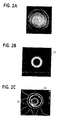
- Figure 2A illustrates the mod(2 ⁇ ) diffractive element and the corresponding intensity in the focal plane of the lens function.
- Figure 2B illustrates an actual example of a diffractive optical element 12 created in accordance with Equation (3).
- Figure 2C illustrates the simulated ring intensity 25 and the measured intensity pattern 29 of the element 12 in Figure 2B.
- a refractive equivalent in accordance with Equation (3) of the phase matching diffractive 12 may be alternately employed.
- This phase matching coupler 12 is not a true beam shaper, since each point in the input plane is mapped into more than one point in the output plane because of the axial singularity. Unlike a diffuser, each point in the input plane is not mapped to every point in the output plane.
- the phase matching coupler 12 allows the desired angular distribution to be substantially maintained along a portion ofthe fiber. This may be quantified by measuring the amount of power within a certain radius of the fiber at a certain distance along the fiber.
- the phase matching of the present invention allows more power to be contained within the desired radii for a longer distance than methods not employing phase matching. For example, by aligning the coupler and a GRIN fiber along the same axis, using a 850 nm source, and matching both the phase and the amplitude, the encircled energy can be maintained to less than 12.5% is a radius of less than 4.5 microns and 75% for a radius less than 15 microns, with no power in the fiber center, for over 6m.
- the light from the coupler is input to the fiber traveling in a circular direction, i.e., the path of the light down the fiber forms a corkscrew. Such traversal is opposed to the linear travel normally occurring down the fiber.
- the input distribution, typically annular, of the input light is maintained along the fiber. Without the phase matching, while the initial input light has the desired shape, this shape is not retained throughout the traversal of the fiber. Therefore, more modal dispersion will be present, with more light in the center of the fiber, if phase matching is not used.
- the phase matching coupler 12 In addition to efficiently coupling the light into the fiber, the phase matching coupler 12 also reduces the power being fedback into the light source 10. Since the phases are matched, and the reflected light will not have the same phase as it did when originally incident on the phase matching coupler 12, the phase matching coupler 12 will not return the light back to the light source as it came. In other words, when the reflected light traverses the system, it will be further deflected by the phase matching coupler 12, thereby reducing the power fedback into the light source 10.
- phase matching coupler 12 only operates sufficiently when the phase matching coupler 12 is far enough away from the fiber so that the phase is sufficiently changed to prevent being redirected in the same manner.
- the phase matching coupler 12 is placed in contact with the end of the fiber, while the coupler will still serve to maintain the input distribution, since the reflected light will have essentially the same phase as the input light, the light will be returned substantially back to the light source as it came.
- the phase matching coupler 12 is placed at least roughly three times the diameter of the beam incident on the fiber, there is sufficient alteration of the phase due to traversal that the reflect light incident on the phase matching coupler 12 will be further deflected.
- a lens 30 in addition to the phase matching coupler 12 as shown in Figure 3.
- This lens 30 is used to shape the light to provide additional reduction in the power fedback to the light source.
- the lens 30 is preferably a diffractive surface that is a combination of a lens function having radially symmetric terms with a negative axicon function.
- the lens 30 may simply form a ring, since the phase matching coupler will prevent the light from being retraced.
- the lens 30 is on a first surface 34 of a wafer 32.
- the phase matching coupler 12 is provided on a second surface 36 of the wafer 32, opposite the first surface. The thickness of the wafer 32 controls the numerical aperture of the image.
- the phase matching coupler 12 may be formed on the same surface as the lens 30.
- the lens 30 allows an annular intensity ring to be optimized for the particular fiber 14. Also, by forming this ring prior to the phase matching coupler 12, a smaller radial segment of the phase matching coupler is used. As can be seen from equation (2), as m increases, the amount of phase twist increases. Thus, rays at the center of the phase matching coupler 12 receive a larger skew angle that rays at the edge of the phase matching coupler. By shaping the light into an annulus, this central portion is avoided, reducing the aberrations introduced by the phase matching coupler 12. Again, the light reflected back from the fiber 14 will not have the same phase as the light incident on the phase matching coupler 12, so the light will be further deflected by the phase matching coupler 12. Since the deflection angles are now altered from that of the light source, the lens 30 will not focus the light back onto the light source, but will further deflect the light away from the light source.
- phase matching coupler 12 is not used, only a reciprocal, phase sensitive system 40.
- An optical element will map an optical distribution, i.e., amplitude and phase distribution in an input plane to an output plane. If an optical element is a reciprocal optical, it will map the same optical distribution in an output plane back to the original optical distribution in the input plane, as long as the light has the same phase and intensity profile.
- Optical systems that perform one-to-one mapping, such as an imaging lens are reciprocal, but are also phase insensitive when performing a mapping between an object plane and an image plane, i.e., a change in phase will not affect the mapping between the image and object planes.
- optical systems such as those that perform a one to many mapping, i.e., in which one point in the input plane is mapped to more than one point in the output plane, while reciprocal, are typically phase sensitive. In other words, a phase change will alter how the light in the output plane is returned to the input plane.
- An example of such a system is a negative axicon.
- this system 40 also creates an intensity ring on the plane at which the fiber 14 is located.
- the reflection from the fiber creates a ring back onto the system 40, but the phase of the light has been altered due to the reflection.
- This change in phase results in the light traversing the system 40 having an increased diameter of the ring in the object plane, rather than returning the ring to the point source of the light source.
- This increased diameter results in most of the light missing the input of the light source, significantly reducing feedback.
- Any other reciprocal, phase sensitive system that results in most of the light avoiding the light source may be used.
- the phase matching coupler 12 may still be employed in any position to increase coupling bandwidth and/or enhance the feedback suppression.
Landscapes
- Physics & Mathematics (AREA)
- General Physics & Mathematics (AREA)
- Optics & Photonics (AREA)
- Optical Couplings Of Light Guides (AREA)
- Gyroscopes (AREA)
- Paper (AREA)
- Diaphragms For Electromechanical Transducers (AREA)
- Manufacture Of Macromolecular Shaped Articles (AREA)
Claims (30)
- Vorrichtung, die von einer Lichtquelle (10) kommendes Licht an einer Eingangsebene in eine optische Faser (14) koppelt, mit einem optischen Element, welches von der Lichtquelle (10) kommendes Licht in die optische Faser (14) koppelt und die Vorrichtung durchlaufendes Licht zum Rückkoppeln in Richtung der Eingangsebene derart zurückleitet, daß sich das zurückkehrende Licht im wesentlichen nicht mit einem Ausgang der Lichtquelle (10) in der Eingangsebene überlappt,
dadurch gekennzeichnet, daß
das optische Element ein Modusangleichungselement (12) ist, bei dem
von der Lichtquelle (10) her empfangenes Licht in einer gewünschten Winkelverteilung verteilt ist, die auf der Achse im wesentlichen null ist und entlang der Faser (14) über mehr als die Fokaltiefe des optischen Elements im wesentlichen beibehalten ist, und von der optischen Faser (14) her empfangenes reflektiertes Licht von der Lichtquelle weggelenkt wird. - Vorrichtung nach Anspruch 1, bei der das Modusangleichungselement (12) ein Beugungselement ist.
- Vorrichtung nach Anspruch 1, bei der das Modusangleichungselement (12) ein Brechungselement ist.
- Vorrichtung nach Anspruch 1, bei der das optische Element eine erste und eine zweite Fläche (34, 36) aufweist, wobei das Modusangleichungselement (12) auf der von der Lichtquelle (10) weiter entfernten zweiten Fläche (36) angeordnet ist.
- Vorrichtung nach Anspruch 4, ferner mit einem Winkelverteilungsveränderungselement (30) auf der ersten Fläche (34).
- Vorrichtung nach Anspruch 5, bei der das Winkelverteilungsveränderungselement (30) ein Ringmuster auf der zweiten Fläche (36) bildet.
- Vorrichtung nach Anspruch 5, bei der das Winkelverteilungsveränderungselement (30) eine Beugungsfläche mit radial symmetrischer Linsenfunktion und einer negativen Axiconfunktion aufweist.
- Vorrichtung nach Anspruch 1, bei der die optische Faser (14) eine multimodale Gradientenfaser ist und das optische Element Licht in höhere Modi der multimodalen Gradientenfaser koppelt, um Verzögerungen durch unterschiedliche Modi zu verringern.
- Vorrichtung nach Anspruch 1, bei der das optische Element eine Beugungsfläche mit einer radial symmetrischen Linsenfunktion und einer negativen Axiconfunktion aufweist.
- Vorrichtung nach Anspruch 1, bei der das optische Element einen Punkt von der Eingangsebene in mehr als einen Punkt auf der optischen Faser (14) abbildet.
- Vorrichtung nach Anspruch 1, ferner mit einer Lichtquelle (10) an einer Eingangsebene.
- Vorrichtung nach Anspruch 11, bei der das Modusangleichungselement (12) ein Beugungselement ist.
- Vorrichtung nach Anspruch 11, bei der das Modusangleichungselement (12) ein Brechungselement ist.
- Vorrichtung nach Anspruch 11, bei der das optische Element eine erste und eine zweite Fläche (34, 36) aufweist, wobei das Modusangleichungselement (12) auf der von der Lichtquelle (10) weiter entfernten zweiten Fläche (36) angeordnet ist.
- Vorrichtung nach Anspruch 14, ferner mit einem Winkelverteilungsveränderungselement (30) auf der ersten Fläche (34).
- Vorrichtung nach Anspruch 15, bei der das Winkelverteilungsveränderungselement (30) ein Ringmuster auf der zweiten Fläche (36) bildet.
- Vorrichtung nach Anspruch 15, bei der das Winkelverteilungsveränderungselement (30) eine Beugungsfläche mit radial symmetrischer Linsenfunktion und einer negativen Axiconfunktion aufweist.
- Vorrichtung nach Anspruch 11, bei der die optische Faser (14) eine multimodale Gradientenfaser ist und das optische Element Licht in höhere Modi der multimodalen Gradientenfaser koppelt, um Verzögerungen durch unterschiedliche Modi zu verringern.
- Vorrichtung nach Anspruch 11, bei der das optische Element eine Beugungsfläche mit einer radial symmetrischen Linsenfunktion und einer negativen Axiconfunktion aufweist.
- Vorrichtung nach Anspruch 11, ferner mit einer Leistungsüberwachungseinrichtung für die Lichtquelle (10).
- Vorrichtung nach Anspruch 20, bei der die Leistungsüberwachungseinrichtung das von der Vorderseite der Lichtquelle (10) ausgegebene Licht überwacht.
- Vorrichtung nach Anspruch 21, ferner mit einem Ablenkelement, das einen Teil des von der Vorderseite der Lichtquelle (10) ausgegebenen Lichts zu der Leistungsüberwachungseinrichtung ablenkt.
- Vorrichtung nach Anspruch 20, bei der das optische Element eine Beugungsfläche mit einer radial symmetrischen Linsenfunktion und einer negativen Axiconfunktion aufweist.
- Vorrichtung nach Anspruch 11, bei der das optische Element einen Punkt von der Eingangsebene in mehr als einen Punkt auf der optischen Faser (14) abbildet.
- Vorrichtung nach Anspruch 1, bei der das Modusangleichungselement (12) ein reziprokes optisches Element ist.
- Vorrichtung nach Anspruch 25, bei der reziproke optische Element ein einzelnes optisches Element ist.
- Vorrichtung nach Anspruch 26, bei der das einzelne optische Element mindestens zwei Flächen aufweist.
- Vorrichtung nach Anspruch 26, bei der das reziproke optische Element ein Axicon ist.
- Vorrichtung nach Anspruch 26, bei der das reziproke optische Element einen Punkt in der Eingangsebene auf mehr als einen Punkt an der Faser abbildet.
- Vorrichtung nach Anspruch 26, bei der eine Phasenveränderung des durch das reziproke optische Element in Richtung der Lichtquelle zurücklaufenden Lichts verhindert, daß Licht einen Ausgang der Lichtquelle in der Eingangsebene im wesentlichen überlappt.
Applications Claiming Priority (3)
| Application Number | Priority Date | Filing Date | Title |
|---|---|---|---|
| US614184 | 1984-05-25 | ||
| US09/614,184 US6496621B1 (en) | 1998-09-22 | 2000-07-11 | Fiber coupler system and associated methods for reducing back reflections |
| PCT/US2001/021761 WO2002005004A2 (en) | 2000-07-11 | 2001-07-10 | Fiber coupler, system and associated methods for reducing back reflections |
Publications (2)
| Publication Number | Publication Date |
|---|---|
| EP1264204A2 EP1264204A2 (de) | 2002-12-11 |
| EP1264204B1 true EP1264204B1 (de) | 2005-05-18 |
Family
ID=24460189
Family Applications (1)
| Application Number | Title | Priority Date | Filing Date |
|---|---|---|---|
| EP01952595A Expired - Lifetime EP1264204B1 (de) | 2000-07-11 | 2001-07-10 | Faserkoppler, system und zugehörige verfahren zur reduktion von rückreflektionen |
Country Status (7)
| Country | Link |
|---|---|
| US (5) | US6496621B1 (de) |
| EP (1) | EP1264204B1 (de) |
| AT (1) | ATE295970T1 (de) |
| AU (1) | AU2001273328A1 (de) |
| CA (1) | CA2403682C (de) |
| DE (1) | DE60110901T2 (de) |
| WO (1) | WO2002005004A2 (de) |
Cited By (3)
| Publication number | Priority date | Publication date | Assignee | Title |
|---|---|---|---|---|
| US9195074B2 (en) | 2012-04-05 | 2015-11-24 | Brien Holden Vision Institute | Lenses, devices and methods for ocular refractive error |
| US9201250B2 (en) | 2012-10-17 | 2015-12-01 | Brien Holden Vision Institute | Lenses, devices, methods and systems for refractive error |
| US9541773B2 (en) | 2012-10-17 | 2017-01-10 | Brien Holden Vision Institute | Lenses, devices, methods and systems for refractive error |
Families Citing this family (40)
| Publication number | Priority date | Publication date | Assignee | Title |
|---|---|---|---|---|
| US6905900B1 (en) | 2000-11-28 | 2005-06-14 | Finisar Corporation | Versatile method and system for single mode VCSELs |
| US7065124B2 (en) | 2000-11-28 | 2006-06-20 | Finlsar Corporation | Electron affinity engineered VCSELs |
| US6822794B2 (en) * | 2000-12-15 | 2004-11-23 | Agilent Technologies, Inc. | Diffractive optical element for providing favorable multi-mode fiber launch and reflection management |
| US6965626B2 (en) | 2002-09-03 | 2005-11-15 | Finisar Corporation | Single mode VCSEL |
| US6807336B2 (en) * | 2002-11-12 | 2004-10-19 | Agilent Technologies, Inc. | Optical lenses |
| US6813293B2 (en) | 2002-11-21 | 2004-11-02 | Finisar Corporation | Long wavelength VCSEL with tunnel junction, and implant |
| US7418016B2 (en) * | 2003-02-13 | 2008-08-26 | Avago Technologies Ecbu Ip (Singapore) Pte. Ltd. | Method and apparatus for modifying the spread of a laser beam |
| US20040222363A1 (en) * | 2003-05-07 | 2004-11-11 | Honeywell International Inc. | Connectorized optical component misalignment detection system |
| US7231114B2 (en) * | 2003-05-21 | 2007-06-12 | Ocp-Europe, Ltd. | Multimode fiber optical fiber transmission system with offset launch single mode long wavelength vertical cavity surface emitting laser transmitter |
| US20040247250A1 (en) * | 2003-06-03 | 2004-12-09 | Honeywell International Inc. | Integrated sleeve pluggable package |
| US7298942B2 (en) | 2003-06-06 | 2007-11-20 | Finisar Corporation | Pluggable optical optic system having a lens fiber stop |
| US7433381B2 (en) | 2003-06-25 | 2008-10-07 | Finisar Corporation | InP based long wavelength VCSEL |
| US7054345B2 (en) | 2003-06-27 | 2006-05-30 | Finisar Corporation | Enhanced lateral oxidation |
| US7277461B2 (en) | 2003-06-27 | 2007-10-02 | Finisar Corporation | Dielectric VCSEL gain guide |
| US7075962B2 (en) | 2003-06-27 | 2006-07-11 | Finisar Corporation | VCSEL having thermal management |
| US6961489B2 (en) | 2003-06-30 | 2005-11-01 | Finisar Corporation | High speed optical system |
| US7149383B2 (en) * | 2003-06-30 | 2006-12-12 | Finisar Corporation | Optical system with reduced back reflection |
| US20060056762A1 (en) * | 2003-07-02 | 2006-03-16 | Honeywell International Inc. | Lens optical coupler |
| US7210857B2 (en) | 2003-07-16 | 2007-05-01 | Finisar Corporation | Optical coupling system |
| US20050013542A1 (en) * | 2003-07-16 | 2005-01-20 | Honeywell International Inc. | Coupler having reduction of reflections to light source |
| US20050013539A1 (en) * | 2003-07-17 | 2005-01-20 | Honeywell International Inc. | Optical coupling system |
| US6887801B2 (en) | 2003-07-18 | 2005-05-03 | Finisar Corporation | Edge bead control method and apparatus |
| US7031363B2 (en) | 2003-10-29 | 2006-04-18 | Finisar Corporation | Long wavelength VCSEL device processing |
| KR100560387B1 (ko) * | 2003-12-24 | 2006-03-13 | 한국전자통신연구원 | 단일/다중 모드 변환기, 및 이를 이용한 광 부호 분할다중 접속 시스템 |
| US7477815B2 (en) * | 2004-05-22 | 2009-01-13 | Ocp-Europe, Ltd | Multi-mode fiber, optical fiber transmission system with offset-launch, single-mode, long-wavelength, vertical cavity surface emitting laser transmitter |
| US8577299B2 (en) | 2004-06-04 | 2013-11-05 | Qualcomm Incorporated | Wireless communication system with configurable cyclic prefix length |
| US8244085B2 (en) * | 2004-07-02 | 2012-08-14 | Finisar Corporation | Optical transceiver interface for multimode fibers |
| KR100810312B1 (ko) * | 2006-02-07 | 2008-03-04 | 삼성전자주식회사 | 다중 채널 방식의 양방향 광 송수신기 |
| US7802930B2 (en) | 2008-03-04 | 2010-09-28 | Jds Uniphase Corporation | Low-noise optical transmitter |
| US20090252192A1 (en) * | 2008-04-08 | 2009-10-08 | Jds Uniphase Corporation | Reduced feedback optical transmitter |
| US8019233B2 (en) * | 2008-05-30 | 2011-09-13 | Avago Technologies Fiber Ip (Singapore) Pte. Ltd. | Method and apparatus for using a hologram to control the optical field distribution of light generated by a light source and launched into an end of an optical waveguide |
| US7796850B2 (en) * | 2008-06-11 | 2010-09-14 | Jds Uniphase Corporation | Multiple-pathway optical transmitter |
| US8442365B2 (en) * | 2009-06-26 | 2013-05-14 | Jds Uniphase Corporation | Optical subassembly for coupling light into an optical waveguide |
| JP5946611B2 (ja) * | 2011-07-15 | 2016-07-06 | 株式会社エンプラス | 光レセプタクルおよびこれを備えた光モジュール |
| CN105527715B (zh) * | 2015-08-13 | 2019-02-22 | 嘉兴驭光光电科技有限公司 | 一种采用衍射光学元件与透镜结合的光照发散角可调节的光学系统 |
| US10451889B2 (en) | 2015-10-22 | 2019-10-22 | Avago Technologies International Sales Pte. Limited | Optical communications module having an optics system that improves link performance, and methods |
| CN106886072B (zh) * | 2015-12-15 | 2019-07-19 | 华为技术有限公司 | 一种一体成型耦合模块 |
| US9841571B1 (en) * | 2017-01-27 | 2017-12-12 | Foxconn Interconnect Technology Limited | Optical coupling system that reduces back reflection and improves mode matching in forward optical coupling using perturbations at a reflective surface |
| US10007072B1 (en) * | 2017-02-28 | 2018-06-26 | Foxconn Interconnect Technology Limited | Optical coupling system having a perturbed curved optical surface that reduces back reflection and improves mode matching in forward optical coupling |
| CN110383113A (zh) * | 2017-03-07 | 2019-10-25 | 日本板硝子株式会社 | 光学部件及光学部件的制造方法 |
Family Cites Families (36)
| Publication number | Priority date | Publication date | Assignee | Title |
|---|---|---|---|---|
| US643508A (en) * | 1899-02-21 | 1900-02-13 | Manander Mott Johnson | Thermostatic governor for incubators. |
| BE789176A (fr) * | 1971-09-24 | 1973-01-15 | Siemens Ag | Dispositif pour l'introduction et l'extraction de lumiere dans des guides d'ondes optiques dielectriques et procede pour sa fabrication |
| FR2295437A1 (fr) * | 1974-12-20 | 1976-07-16 | Thomson Csf | Systeme de liaison par transmission optique au moyen de guides de lumiere |
| US4709413A (en) * | 1982-09-10 | 1987-11-24 | American Telephone And Telegraph Company, At&T Bell Laboratories | Bidirectional fiber optic systems |
| US4834484A (en) * | 1987-07-09 | 1989-05-30 | University Of Houston-University Park | Optical fiber coupler including refractive means for producing an annular beam |
| DE3733019A1 (de) * | 1987-09-30 | 1989-04-13 | Siemens Ag | Koppelanordnung zum einkoppeln von licht einer halbleiterlaserdiode in eine multimode-glasfaser |
| US4799755A (en) * | 1987-12-21 | 1989-01-24 | General Electric Company | Laser materials processing with a lensless fiber optic output coupler |
| JPH03166531A (ja) * | 1989-11-27 | 1991-07-18 | Pioneer Electron Corp | ファイバー型光波長変換装置 |
| JPH0434505A (ja) * | 1990-05-31 | 1992-02-05 | Fujitsu Ltd | 光導波路型デバイスとその製造方法 |
| US5117472A (en) * | 1990-12-28 | 1992-05-26 | At&T Bell Laboratories | Optical coupler with mode-mixing refractive microparticles |
| GB9101093D0 (en) * | 1991-01-17 | 1991-02-27 | Atomic Energy Authority Uk | Focussing means |
| US5113244A (en) * | 1991-02-06 | 1992-05-12 | General Dynamics Corporation, Electronics Division | Fiber optic combiner/splitter |
| JP3294870B2 (ja) * | 1991-07-04 | 2002-06-24 | 旭光学工業株式会社 | ズームレンズ |
| US5243681A (en) * | 1992-04-13 | 1993-09-07 | Amp Incorporated | Aperture disk attenuator for laser diode connector |
| US5278679A (en) * | 1992-08-03 | 1994-01-11 | Davis Jeffrey A | Sub-diffraction limited focusing lenses |
| JPH06120609A (ja) * | 1992-10-06 | 1994-04-28 | Matsushita Electric Ind Co Ltd | 発光装置および受光装置とその製造方法 |
| GB2271933B (en) | 1992-10-28 | 1996-11-27 | Smiths Ind Med Syst Inc | Suction catheter assemblies |
| JP3277573B2 (ja) * | 1992-10-30 | 2002-04-22 | 住友電気工業株式会社 | 半導体レーザモジュール |
| US5405659A (en) * | 1993-03-05 | 1995-04-11 | University Of Puerto Rico | Method and apparatus for removing material from a target by use of a ring-shaped elliptical laser beam and depositing the material onto a substrate |
| US5416862A (en) * | 1993-04-07 | 1995-05-16 | At&T Corp. | Lightwave transmission system using selected optical modes |
| US5504826A (en) * | 1994-03-08 | 1996-04-02 | Nec Corporation | Optical module for subcarrier multiplexed optical transmission system |
| US5638396A (en) * | 1994-09-19 | 1997-06-10 | Textron Systems Corporation | Laser ultrasonics-based material analysis system and method |
| DE4440976A1 (de) * | 1994-11-17 | 1996-05-23 | Ant Nachrichtentech | Optische Sende- und Empfangseinrichtung mit einem oberflächenemittierenden Laser |
| US5661835A (en) * | 1995-01-19 | 1997-08-26 | Sumitomo Electric Industries, Ltd. | Optical composite module and method of assembling the same |
| JPH09216266A (ja) | 1996-02-13 | 1997-08-19 | Toyo Mach & Metal Co Ltd | 射出成形機の制御方法 |
| GB9605011D0 (en) | 1996-03-08 | 1996-05-08 | Hewlett Packard Co | Multimode communications systems |
| JPH1096839A (ja) | 1996-09-20 | 1998-04-14 | Sumitomo Electric Ind Ltd | 半導体レーザモジュールの製造方法 |
| US5763870A (en) * | 1996-12-13 | 1998-06-09 | Hewlett-Packard Company | Method and system for operating a laser device employing an integral power-regulation sensor |
| US5898802A (en) * | 1997-03-27 | 1999-04-27 | Cogent Light Technologies, Inc. | Coupling method and apparatus for coupling polymer fibers to a light source for improving power handling capabilities of the polymer fibers |
| JP3792040B2 (ja) * | 1998-03-06 | 2006-06-28 | 松下電器産業株式会社 | 双方向光半導体装置 |
| US6314223B1 (en) | 1998-08-31 | 2001-11-06 | Digital Optics Corporation | Diffractive vertical cavity surface emitting laser power monitor and system |
| EP1033597A4 (de) * | 1998-09-17 | 2005-09-28 | Matsushita Electric Industrial Co Ltd | Halbleiterlasermodul und koppellinse |
| US6243508B1 (en) * | 1999-06-01 | 2001-06-05 | Picolight Incorporated | Electro-opto-mechanical assembly for coupling a light source or receiver to an optical waveguide |
| US6600845B1 (en) * | 1999-10-18 | 2003-07-29 | Digital Optics Corporation | Integrated parallel transmitter |
| US6822794B2 (en) * | 2000-12-15 | 2004-11-23 | Agilent Technologies, Inc. | Diffractive optical element for providing favorable multi-mode fiber launch and reflection management |
| US7149383B2 (en) * | 2003-06-30 | 2006-12-12 | Finisar Corporation | Optical system with reduced back reflection |
-
2000
- 2000-07-11 US US09/614,184 patent/US6496621B1/en not_active Expired - Lifetime
-
2001
- 2001-07-10 DE DE60110901T patent/DE60110901T2/de not_active Expired - Lifetime
- 2001-07-10 AU AU2001273328A patent/AU2001273328A1/en not_active Abandoned
- 2001-07-10 AT AT01952595T patent/ATE295970T1/de not_active IP Right Cessation
- 2001-07-10 CA CA002403682A patent/CA2403682C/en not_active Expired - Fee Related
- 2001-07-10 WO PCT/US2001/021761 patent/WO2002005004A2/en not_active Ceased
- 2001-07-10 EP EP01952595A patent/EP1264204B1/de not_active Expired - Lifetime
-
2002
- 2002-12-17 US US10/320,525 patent/US7221823B2/en not_active Expired - Lifetime
-
2007
- 2007-05-18 US US11/802,044 patent/US7343069B2/en not_active Expired - Fee Related
-
2008
- 2008-03-10 US US12/073,748 patent/US7529446B2/en not_active Expired - Fee Related
-
2009
- 2009-05-04 US US12/453,229 patent/US7769258B2/en not_active Expired - Fee Related
Cited By (7)
| Publication number | Priority date | Publication date | Assignee | Title |
|---|---|---|---|---|
| US9195074B2 (en) | 2012-04-05 | 2015-11-24 | Brien Holden Vision Institute | Lenses, devices and methods for ocular refractive error |
| US9535263B2 (en) | 2012-04-05 | 2017-01-03 | Brien Holden Vision Institute | Lenses, devices, methods and systems for refractive error |
| US9575334B2 (en) | 2012-04-05 | 2017-02-21 | Brien Holden Vision Institute | Lenses, devices and methods of ocular refractive error |
| US10203522B2 (en) | 2012-04-05 | 2019-02-12 | Brien Holden Vision Institute | Lenses, devices, methods and systems for refractive error |
| US10209535B2 (en) | 2012-04-05 | 2019-02-19 | Brien Holden Vision Institute | Lenses, devices and methods for ocular refractive error |
| US9201250B2 (en) | 2012-10-17 | 2015-12-01 | Brien Holden Vision Institute | Lenses, devices, methods and systems for refractive error |
| US9541773B2 (en) | 2012-10-17 | 2017-01-10 | Brien Holden Vision Institute | Lenses, devices, methods and systems for refractive error |
Also Published As
| Publication number | Publication date |
|---|---|
| CA2403682C (en) | 2009-10-06 |
| US20070223094A1 (en) | 2007-09-27 |
| ATE295970T1 (de) | 2005-06-15 |
| US7769258B2 (en) | 2010-08-03 |
| WO2002005004A3 (en) | 2002-07-18 |
| US20090226134A1 (en) | 2009-09-10 |
| US6496621B1 (en) | 2002-12-17 |
| AU2001273328A1 (en) | 2002-01-21 |
| US7343069B2 (en) | 2008-03-11 |
| DE60110901T2 (de) | 2006-03-23 |
| EP1264204A2 (de) | 2002-12-11 |
| DE60110901D1 (de) | 2005-06-23 |
| WO2002005004A2 (en) | 2002-01-17 |
| US20080159695A1 (en) | 2008-07-03 |
| US7221823B2 (en) | 2007-05-22 |
| CA2403682A1 (en) | 2002-01-17 |
| US20030072526A1 (en) | 2003-04-17 |
| US7529446B2 (en) | 2009-05-05 |
Similar Documents
| Publication | Publication Date | Title |
|---|---|---|
| US6496621B1 (en) | Fiber coupler system and associated methods for reducing back reflections | |
| US6530697B1 (en) | Multi-mode fiber coupler, system and associated methods | |
| EP3084491B1 (de) | Multimodaler optischer verbinder | |
| US6600845B1 (en) | Integrated parallel transmitter | |
| US8821035B2 (en) | Optical element and system using the same | |
| JP2006522943A (ja) | ビーム成形と、薄いシリコン導波管への外部ソースおよび光学系の嵌合に関連する損失を減らす実用的方法 | |
| US11693185B2 (en) | Optical connector with tilted mirror | |
| TW200411241A (en) | Symmetric, bi-aspheric lens for use in optical fiber collimator assemblies | |
| US6483961B1 (en) | Dual refraction index collimator for an optical switch | |
| JPH02248905A (ja) | 光ファイバー結合装置 | |
| JP2786322B2 (ja) | 反射軽減集成装置 | |
| EP2518549B1 (de) | Räumlicher Multiplexer zur Kopplung von Einzelmodusfasern an eine Mehrkernfaser | |
| US20050211884A1 (en) | Optical receiver with high dynamic range | |
| CN109633837A (zh) | 光模块 | |
| CN108387978B (zh) | 光耦合系统及光耦合方法 | |
| JP2012518814A (ja) | 光ファイバ回転接合に使用するための低損失コリメータ | |
| US7011455B2 (en) | Opto-electronic TO-package and method for laser | |
| US10007072B1 (en) | Optical coupling system having a perturbed curved optical surface that reduces back reflection and improves mode matching in forward optical coupling | |
| US20030174959A1 (en) | Waveguide to waveguide monitor | |
| CN115421247A (zh) | 一种光耦合结构 | |
| JPH0414762B2 (de) | ||
| Azadeh | Light Coupling and Passive Optical Devices | |
| JP2005352364A (ja) | 複合光学機能素子 |
Legal Events
| Date | Code | Title | Description |
|---|---|---|---|
| PUAI | Public reference made under article 153(3) epc to a published international application that has entered the european phase |
Free format text: ORIGINAL CODE: 0009012 |
|
| 17P | Request for examination filed |
Effective date: 20020909 |
|
| AK | Designated contracting states |
Kind code of ref document: A2 Designated state(s): AT BE CH CY DE DK ES FI FR GB GR IE IT LI LU MC NL PT SE TR |
|
| AX | Request for extension of the european patent |
Free format text: AL;LT;LV;MK;RO;SI |
|
| 17Q | First examination report despatched |
Effective date: 20030703 |
|
| GRAP | Despatch of communication of intention to grant a patent |
Free format text: ORIGINAL CODE: EPIDOSNIGR1 |
|
| GRAS | Grant fee paid |
Free format text: ORIGINAL CODE: EPIDOSNIGR3 |
|
| GRAA | (expected) grant |
Free format text: ORIGINAL CODE: 0009210 |
|
| AK | Designated contracting states |
Kind code of ref document: B1 Designated state(s): AT BE CH CY DE DK ES FI FR GB GR IE IT LI LU MC NL PT SE TR |
|
| PG25 | Lapsed in a contracting state [announced via postgrant information from national office to epo] |
Ref country code: IT Free format text: LAPSE BECAUSE OF FAILURE TO SUBMIT A TRANSLATION OF THE DESCRIPTION OR TO PAY THE FEE WITHIN THE PRESCRIBED TIME-LIMIT;WARNING: LAPSES OF ITALIAN PATENTS WITH EFFECTIVE DATE BEFORE 2007 MAY HAVE OCCURRED AT ANY TIME BEFORE 2007. THE CORRECT EFFECTIVE DATE MAY BE DIFFERENT FROM THE ONE RECORDED. Effective date: 20050518 Ref country code: AT Free format text: LAPSE BECAUSE OF FAILURE TO SUBMIT A TRANSLATION OF THE DESCRIPTION OR TO PAY THE FEE WITHIN THE PRESCRIBED TIME-LIMIT Effective date: 20050518 Ref country code: TR Free format text: LAPSE BECAUSE OF FAILURE TO SUBMIT A TRANSLATION OF THE DESCRIPTION OR TO PAY THE FEE WITHIN THE PRESCRIBED TIME-LIMIT Effective date: 20050518 Ref country code: FI Free format text: LAPSE BECAUSE OF FAILURE TO SUBMIT A TRANSLATION OF THE DESCRIPTION OR TO PAY THE FEE WITHIN THE PRESCRIBED TIME-LIMIT Effective date: 20050518 Ref country code: ES Free format text: LAPSE BECAUSE OF FAILURE TO SUBMIT A TRANSLATION OF THE DESCRIPTION OR TO PAY THE FEE WITHIN THE PRESCRIBED TIME-LIMIT Effective date: 20050518 Ref country code: NL Free format text: LAPSE BECAUSE OF FAILURE TO SUBMIT A TRANSLATION OF THE DESCRIPTION OR TO PAY THE FEE WITHIN THE PRESCRIBED TIME-LIMIT Effective date: 20050518 Ref country code: BE Free format text: LAPSE BECAUSE OF FAILURE TO SUBMIT A TRANSLATION OF THE DESCRIPTION OR TO PAY THE FEE WITHIN THE PRESCRIBED TIME-LIMIT Effective date: 20050518 |
|
| REG | Reference to a national code |
Ref country code: GB Ref legal event code: FG4D |
|
| REG | Reference to a national code |
Ref country code: CH Ref legal event code: EP |
|
| REG | Reference to a national code |
Ref country code: IE Ref legal event code: FG4D |
|
| REF | Corresponds to: |
Ref document number: 60110901 Country of ref document: DE Date of ref document: 20050623 Kind code of ref document: P |
|
| PG25 | Lapsed in a contracting state [announced via postgrant information from national office to epo] |
Ref country code: CY Free format text: LAPSE BECAUSE OF FAILURE TO SUBMIT A TRANSLATION OF THE DESCRIPTION OR TO PAY THE FEE WITHIN THE PRESCRIBED TIME-LIMIT Effective date: 20050710 Ref country code: LU Free format text: LAPSE BECAUSE OF NON-PAYMENT OF DUE FEES Effective date: 20050710 |
|
| PG25 | Lapsed in a contracting state [announced via postgrant information from national office to epo] |
Ref country code: IE Free format text: LAPSE BECAUSE OF NON-PAYMENT OF DUE FEES Effective date: 20050711 |
|
| PG25 | Lapsed in a contracting state [announced via postgrant information from national office to epo] |
Ref country code: MC Free format text: LAPSE BECAUSE OF NON-PAYMENT OF DUE FEES Effective date: 20050731 |
|
| PG25 | Lapsed in a contracting state [announced via postgrant information from national office to epo] |
Ref country code: SE Free format text: LAPSE BECAUSE OF FAILURE TO SUBMIT A TRANSLATION OF THE DESCRIPTION OR TO PAY THE FEE WITHIN THE PRESCRIBED TIME-LIMIT Effective date: 20050818 Ref country code: GR Free format text: LAPSE BECAUSE OF FAILURE TO SUBMIT A TRANSLATION OF THE DESCRIPTION OR TO PAY THE FEE WITHIN THE PRESCRIBED TIME-LIMIT Effective date: 20050818 Ref country code: DK Free format text: LAPSE BECAUSE OF FAILURE TO SUBMIT A TRANSLATION OF THE DESCRIPTION OR TO PAY THE FEE WITHIN THE PRESCRIBED TIME-LIMIT Effective date: 20050818 |
|
| REG | Reference to a national code |
Ref country code: CH Ref legal event code: NV Representative=s name: PETER RUTZ |
|
| PG25 | Lapsed in a contracting state [announced via postgrant information from national office to epo] |
Ref country code: PT Free format text: LAPSE BECAUSE OF FAILURE TO SUBMIT A TRANSLATION OF THE DESCRIPTION OR TO PAY THE FEE WITHIN THE PRESCRIBED TIME-LIMIT Effective date: 20051024 |
|
| NLV1 | Nl: lapsed or annulled due to failure to fulfill the requirements of art. 29p and 29m of the patents act | ||
| PLBE | No opposition filed within time limit |
Free format text: ORIGINAL CODE: 0009261 |
|
| STAA | Information on the status of an ep patent application or granted ep patent |
Free format text: STATUS: NO OPPOSITION FILED WITHIN TIME LIMIT |
|
| ET | Fr: translation filed | ||
| REG | Reference to a national code |
Ref country code: IE Ref legal event code: MM4A |
|
| 26N | No opposition filed |
Effective date: 20060221 |
|
| REG | Reference to a national code |
Ref country code: CH Ref legal event code: PFA Owner name: TESSERA NORTH AMERICA, INC. Free format text: DIGITAL OPTICS CORPORATION#9815 DAVID TAYLOR DRIVE#CHARLOTTE, NC 28262 (US) -TRANSFER TO- TESSERA NORTH AMERICA, INC.#9815 DAVID TAYLOR DRIVE#CHARLOTTE, NC 28262 (US) |
|
| REG | Reference to a national code |
Ref country code: FR Ref legal event code: CD |
|
| REG | Reference to a national code |
Ref country code: CH Ref legal event code: PFA Owner name: DIGITALOPTICS CORPORATION EAST Free format text: TESSERA NORTH AMERICA, INC.#9815 DAVID TAYLOR DRIVE#CHARLOTTE, NC 28262 (US) -TRANSFER TO- DIGITALOPTICS CORPORATION EAST#9815 DAVID TAYLOR DRIVE#CHARLOTTE, NC 28262 (US) |
|
| REG | Reference to a national code |
Ref country code: DE Ref legal event code: R082 Ref document number: 60110901 Country of ref document: DE Representative=s name: PATENTANWAELTE VON KREISLER, SELTING, WERNER, DE |
|
| REG | Reference to a national code |
Ref country code: FR Ref legal event code: CD Owner name: DIGITALOPTICS CORPORATION EAST, US Effective date: 20111024 |
|
| REG | Reference to a national code |
Ref country code: DE Ref legal event code: R082 Ref document number: 60110901 Country of ref document: DE Representative=s name: VON KREISLER SELTING WERNER - PARTNERSCHAFT VO, DE Effective date: 20111017 Ref country code: DE Ref legal event code: R081 Ref document number: 60110901 Country of ref document: DE Owner name: DIGITALOPTICS CORPORATION EAST (N. D. GES. D. , US Free format text: FORMER OWNER: TESSERA NORTH AMERICA.INC.(N. D. GES. D. STAATES DELAWARE), CHARLOTTE, N.C., US Effective date: 20111017 Ref country code: DE Ref legal event code: R081 Ref document number: 60110901 Country of ref document: DE Owner name: FLIR SYSTEMS TRADING BELGIUM BVBA, BE Free format text: FORMER OWNER: TESSERA NORTH AMERICA.INC.(N. D. GES. D. STAATES DELAWARE), CHARLOTTE, N.C., US Effective date: 20111017 Ref country code: DE Ref legal event code: R082 Ref document number: 60110901 Country of ref document: DE Representative=s name: DOMPATENT VON KREISLER SELTING WERNER - PARTNE, DE Effective date: 20111017 |
|
| REG | Reference to a national code |
Ref country code: CH Ref legal event code: PUE Owner name: FLYR SYSTEMS TRADING BELGIUM, BE Free format text: FORMER OWNER: DIGITALOPTICS CORPORATION EAST, US |
|
| REG | Reference to a national code |
Ref country code: CH Ref legal event code: PK Free format text: BERICHTIGUNG INHABER |
|
| REG | Reference to a national code |
Ref country code: DE Ref legal event code: R082 Ref document number: 60110901 Country of ref document: DE Representative=s name: VON KREISLER SELTING WERNER - PARTNERSCHAFT VO, DE |
|
| PGFP | Annual fee paid to national office [announced via postgrant information from national office to epo] |
Ref country code: CH Payment date: 20140714 Year of fee payment: 14 |
|
| REG | Reference to a national code |
Ref country code: CH Ref legal event code: PK Free format text: BERICHTIGUNG INHABER |
|
| REG | Reference to a national code |
Ref country code: DE Ref legal event code: R081 Ref document number: 60110901 Country of ref document: DE Owner name: FLIR SYSTEMS TRADING BELGIUM BVBA, BE Free format text: FORMER OWNER: DIGITALOPTICS CORPORATION EAST (N. D. GES. D. STAATES DELAWARE), CHARLOTTE, N.C., US Effective date: 20141017 Ref country code: DE Ref legal event code: R082 Ref document number: 60110901 Country of ref document: DE Representative=s name: VON KREISLER SELTING WERNER - PARTNERSCHAFT VO, DE Effective date: 20141017 Ref country code: DE Ref legal event code: R082 Ref document number: 60110901 Country of ref document: DE Representative=s name: DOMPATENT VON KREISLER SELTING WERNER - PARTNE, DE Effective date: 20141017 |
|
| PGFP | Annual fee paid to national office [announced via postgrant information from national office to epo] |
Ref country code: FR Payment date: 20140723 Year of fee payment: 14 |
|
| REG | Reference to a national code |
Ref country code: GB Ref legal event code: 732E Free format text: REGISTERED BETWEEN 20141106 AND 20141112 |
|
| PGFP | Annual fee paid to national office [announced via postgrant information from national office to epo] |
Ref country code: GB Payment date: 20150626 Year of fee payment: 15 |
|
| REG | Reference to a national code |
Ref country code: CH Ref legal event code: PL |
|
| PG25 | Lapsed in a contracting state [announced via postgrant information from national office to epo] |
Ref country code: LI Free format text: LAPSE BECAUSE OF NON-PAYMENT OF DUE FEES Effective date: 20150731 Ref country code: CH Free format text: LAPSE BECAUSE OF NON-PAYMENT OF DUE FEES Effective date: 20150731 |
|
| REG | Reference to a national code |
Ref country code: FR Ref legal event code: ST Effective date: 20160331 |
|
| PG25 | Lapsed in a contracting state [announced via postgrant information from national office to epo] |
Ref country code: FR Free format text: LAPSE BECAUSE OF NON-PAYMENT OF DUE FEES Effective date: 20150731 |
|
| GBPC | Gb: european patent ceased through non-payment of renewal fee |
Effective date: 20160710 |
|
| PG25 | Lapsed in a contracting state [announced via postgrant information from national office to epo] |
Ref country code: GB Free format text: LAPSE BECAUSE OF NON-PAYMENT OF DUE FEES Effective date: 20160710 |
|
| REG | Reference to a national code |
Ref country code: DE Ref legal event code: R082 Ref document number: 60110901 Country of ref document: DE Representative=s name: DILG HAEUSLER SCHINDELMANN PATENTANWALTSGESELL, DE Ref country code: DE Ref legal event code: R081 Ref document number: 60110901 Country of ref document: DE Owner name: AVAGO TECHNOLOGIES INTERNATIONAL SALES PTE. LI, SG Free format text: FORMER OWNER: FLIR SYSTEMS TRADING BELGIUM BVBA, MEER, BE Ref country code: DE Ref legal event code: R082 Ref document number: 60110901 Country of ref document: DE Representative=s name: DILG, HAEUSLER, SCHINDELMANN PATENTANWALTSGESE, DE Ref country code: DE Ref legal event code: R081 Ref document number: 60110901 Country of ref document: DE Owner name: BROADCOM INTERNATIONAL PTE. LTD., SG Free format text: FORMER OWNER: FLIR SYSTEMS TRADING BELGIUM BVBA, MEER, BE |
|
| PGFP | Annual fee paid to national office [announced via postgrant information from national office to epo] |
Ref country code: DE Payment date: 20190729 Year of fee payment: 19 |
|
| REG | Reference to a national code |
Ref country code: DE Ref legal event code: R082 Ref document number: 60110901 Country of ref document: DE Representative=s name: DILG, HAEUSLER, SCHINDELMANN PATENTANWALTSGESE, DE Ref country code: DE Ref legal event code: R081 Ref document number: 60110901 Country of ref document: DE Owner name: BROADCOM INTERNATIONAL PTE. LTD., SG Free format text: FORMER OWNER: AVAGO TECHNOLOGIES INTERNATIONAL SALES PTE. LIMITED, SINGAPORE, SG |
|
| REG | Reference to a national code |
Ref country code: DE Ref legal event code: R119 Ref document number: 60110901 Country of ref document: DE |
|
| PG25 | Lapsed in a contracting state [announced via postgrant information from national office to epo] |
Ref country code: DE Free format text: LAPSE BECAUSE OF NON-PAYMENT OF DUE FEES Effective date: 20210202 |