EP1264228B1 - Regulateur de gaz electronique a volume eleve - Google Patents
Regulateur de gaz electronique a volume eleve Download PDFInfo
- Publication number
- EP1264228B1 EP1264228B1 EP01902189A EP01902189A EP1264228B1 EP 1264228 B1 EP1264228 B1 EP 1264228B1 EP 01902189 A EP01902189 A EP 01902189A EP 01902189 A EP01902189 A EP 01902189A EP 1264228 B1 EP1264228 B1 EP 1264228B1
- Authority
- EP
- European Patent Office
- Prior art keywords
- pressure
- gas
- valve
- regulator
- outlet
- Prior art date
- Legal status (The legal status is an assumption and is not a legal conclusion. Google has not performed a legal analysis and makes no representation as to the accuracy of the status listed.)
- Expired - Lifetime
Links
- 230000001105 regulatory effect Effects 0.000 claims abstract description 24
- 230000001276 controlling effect Effects 0.000 claims abstract description 17
- 239000000446 fuel Substances 0.000 claims description 56
- 230000007246 mechanism Effects 0.000 claims description 46
- 230000004044 response Effects 0.000 claims description 21
- 230000000740 bleeding effect Effects 0.000 claims description 7
- 238000002485 combustion reaction Methods 0.000 claims description 5
- 230000009849 deactivation Effects 0.000 claims description 5
- 238000012544 monitoring process Methods 0.000 claims description 4
- 238000004891 communication Methods 0.000 claims description 3
- 239000007789 gas Substances 0.000 description 139
- 238000012360 testing method Methods 0.000 description 28
- VNWKTOKETHGBQD-UHFFFAOYSA-N methane Chemical compound C VNWKTOKETHGBQD-UHFFFAOYSA-N 0.000 description 16
- 230000000694 effects Effects 0.000 description 14
- 230000008859 change Effects 0.000 description 13
- 238000005336 cracking Methods 0.000 description 10
- 125000004122 cyclic group Chemical group 0.000 description 8
- 230000003247 decreasing effect Effects 0.000 description 8
- 239000003345 natural gas Substances 0.000 description 8
- 230000007423 decrease Effects 0.000 description 6
- 238000013022 venting Methods 0.000 description 6
- 230000008878 coupling Effects 0.000 description 5
- 238000010168 coupling process Methods 0.000 description 5
- 238000005859 coupling reaction Methods 0.000 description 5
- 238000013461 design Methods 0.000 description 4
- 238000000034 method Methods 0.000 description 4
- 238000007599 discharging Methods 0.000 description 3
- 230000003068 static effect Effects 0.000 description 3
- 238000004458 analytical method Methods 0.000 description 2
- 230000033228 biological regulation Effects 0.000 description 2
- 238000004422 calculation algorithm Methods 0.000 description 2
- 238000006243 chemical reaction Methods 0.000 description 2
- 230000000052 comparative effect Effects 0.000 description 2
- 239000012530 fluid Substances 0.000 description 2
- 239000002828 fuel tank Substances 0.000 description 2
- 238000010438 heat treatment Methods 0.000 description 2
- 238000010998 test method Methods 0.000 description 2
- 230000008901 benefit Effects 0.000 description 1
- 238000004364 calculation method Methods 0.000 description 1
- 230000001351 cycling effect Effects 0.000 description 1
- 230000007812 deficiency Effects 0.000 description 1
- 238000006073 displacement reaction Methods 0.000 description 1
- 230000009977 dual effect Effects 0.000 description 1
- 238000002474 experimental method Methods 0.000 description 1
- 238000013213 extrapolation Methods 0.000 description 1
- 238000001914 filtration Methods 0.000 description 1
- 239000003502 gasoline Substances 0.000 description 1
- 231100001261 hazardous Toxicity 0.000 description 1
- 238000013101 initial test Methods 0.000 description 1
- 238000002347 injection Methods 0.000 description 1
- 239000007924 injection Substances 0.000 description 1
- 239000007788 liquid Substances 0.000 description 1
- 238000004519 manufacturing process Methods 0.000 description 1
- 238000007619 statistical method Methods 0.000 description 1
- 238000003860 storage Methods 0.000 description 1
- 230000001052 transient effect Effects 0.000 description 1
Images







Classifications
-
- F—MECHANICAL ENGINEERING; LIGHTING; HEATING; WEAPONS; BLASTING
- F02—COMBUSTION ENGINES; HOT-GAS OR COMBUSTION-PRODUCT ENGINE PLANTS
- F02M—SUPPLYING COMBUSTION ENGINES IN GENERAL WITH COMBUSTIBLE MIXTURES OR CONSTITUENTS THEREOF
- F02M21/00—Apparatus for supplying engines with non-liquid fuels, e.g. gaseous fuels stored in liquid form
- F02M21/02—Apparatus for supplying engines with non-liquid fuels, e.g. gaseous fuels stored in liquid form for gaseous fuels
- F02M21/0218—Details on the gaseous fuel supply system, e.g. tanks, valves, pipes, pumps, rails, injectors or mixers
- F02M21/023—Valves; Pressure or flow regulators in the fuel supply or return system
- F02M21/0236—Multi-way valves; Multiple valves forming a multi-way valve system
-
- F—MECHANICAL ENGINEERING; LIGHTING; HEATING; WEAPONS; BLASTING
- F02—COMBUSTION ENGINES; HOT-GAS OR COMBUSTION-PRODUCT ENGINE PLANTS
- F02D—CONTROLLING COMBUSTION ENGINES
- F02D19/00—Controlling engines characterised by their use of non-liquid fuels, pluralities of fuels, or non-fuel substances added to the combustible mixtures
- F02D19/02—Controlling engines characterised by their use of non-liquid fuels, pluralities of fuels, or non-fuel substances added to the combustible mixtures peculiar to engines working with gaseous fuels
- F02D19/021—Control of components of the fuel supply system
- F02D19/022—Control of components of the fuel supply system to adjust the fuel pressure, temperature or composition
-
- F—MECHANICAL ENGINEERING; LIGHTING; HEATING; WEAPONS; BLASTING
- F02—COMBUSTION ENGINES; HOT-GAS OR COMBUSTION-PRODUCT ENGINE PLANTS
- F02D—CONTROLLING COMBUSTION ENGINES
- F02D41/00—Electrical control of supply of combustible mixture or its constituents
- F02D41/0025—Controlling engines characterised by use of non-liquid fuels, pluralities of fuels, or non-fuel substances added to the combustible mixtures
- F02D41/0027—Controlling engines characterised by use of non-liquid fuels, pluralities of fuels, or non-fuel substances added to the combustible mixtures the fuel being gaseous
-
- F—MECHANICAL ENGINEERING; LIGHTING; HEATING; WEAPONS; BLASTING
- F02—COMBUSTION ENGINES; HOT-GAS OR COMBUSTION-PRODUCT ENGINE PLANTS
- F02M—SUPPLYING COMBUSTION ENGINES IN GENERAL WITH COMBUSTIBLE MIXTURES OR CONSTITUENTS THEREOF
- F02M21/00—Apparatus for supplying engines with non-liquid fuels, e.g. gaseous fuels stored in liquid form
- F02M21/02—Apparatus for supplying engines with non-liquid fuels, e.g. gaseous fuels stored in liquid form for gaseous fuels
- F02M21/0218—Details on the gaseous fuel supply system, e.g. tanks, valves, pipes, pumps, rails, injectors or mixers
- F02M21/023—Valves; Pressure or flow regulators in the fuel supply or return system
- F02M21/0233—Details of actuators therefor
-
- F—MECHANICAL ENGINEERING; LIGHTING; HEATING; WEAPONS; BLASTING
- F02—COMBUSTION ENGINES; HOT-GAS OR COMBUSTION-PRODUCT ENGINE PLANTS
- F02M—SUPPLYING COMBUSTION ENGINES IN GENERAL WITH COMBUSTIBLE MIXTURES OR CONSTITUENTS THEREOF
- F02M21/00—Apparatus for supplying engines with non-liquid fuels, e.g. gaseous fuels stored in liquid form
- F02M21/02—Apparatus for supplying engines with non-liquid fuels, e.g. gaseous fuels stored in liquid form for gaseous fuels
- F02M21/0218—Details on the gaseous fuel supply system, e.g. tanks, valves, pipes, pumps, rails, injectors or mixers
- F02M21/023—Valves; Pressure or flow regulators in the fuel supply or return system
- F02M21/0239—Pressure or flow regulators therefor
-
- G—PHYSICS
- G05—CONTROLLING; REGULATING
- G05D—SYSTEMS FOR CONTROLLING OR REGULATING NON-ELECTRIC VARIABLES
- G05D16/00—Control of fluid pressure
- G05D16/20—Control of fluid pressure characterised by the use of electric means
- G05D16/2006—Control of fluid pressure characterised by the use of electric means with direct action of electric energy on controlling means
- G05D16/2013—Control of fluid pressure characterised by the use of electric means with direct action of electric energy on controlling means using throttling means as controlling means
- G05D16/2024—Control of fluid pressure characterised by the use of electric means with direct action of electric energy on controlling means using throttling means as controlling means the throttling means being a multiple-way valve
-
- G—PHYSICS
- G05—CONTROLLING; REGULATING
- G05D—SYSTEMS FOR CONTROLLING OR REGULATING NON-ELECTRIC VARIABLES
- G05D16/00—Control of fluid pressure
- G05D16/20—Control of fluid pressure characterised by the use of electric means
- G05D16/2093—Control of fluid pressure characterised by the use of electric means with combination of electric and non-electric auxiliary power
- G05D16/2097—Control of fluid pressure characterised by the use of electric means with combination of electric and non-electric auxiliary power using pistons within the main valve
-
- F—MECHANICAL ENGINEERING; LIGHTING; HEATING; WEAPONS; BLASTING
- F02—COMBUSTION ENGINES; HOT-GAS OR COMBUSTION-PRODUCT ENGINE PLANTS
- F02D—CONTROLLING COMBUSTION ENGINES
- F02D41/00—Electrical control of supply of combustible mixture or its constituents
- F02D41/20—Output circuits, e.g. for controlling currents in command coils
- F02D2041/202—Output circuits, e.g. for controlling currents in command coils characterised by the control of the circuit
- F02D2041/2024—Output circuits, e.g. for controlling currents in command coils characterised by the control of the circuit the control switching a load after time-on and time-off pulses
- F02D2041/2027—Control of the current by pulse width modulation or duty cycle control
-
- F—MECHANICAL ENGINEERING; LIGHTING; HEATING; WEAPONS; BLASTING
- F02—COMBUSTION ENGINES; HOT-GAS OR COMBUSTION-PRODUCT ENGINE PLANTS
- F02D—CONTROLLING COMBUSTION ENGINES
- F02D2250/00—Engine control related to specific problems or objectives
- F02D2250/31—Control of the fuel pressure
-
- Y—GENERAL TAGGING OF NEW TECHNOLOGICAL DEVELOPMENTS; GENERAL TAGGING OF CROSS-SECTIONAL TECHNOLOGIES SPANNING OVER SEVERAL SECTIONS OF THE IPC; TECHNICAL SUBJECTS COVERED BY FORMER USPC CROSS-REFERENCE ART COLLECTIONS [XRACs] AND DIGESTS
- Y02—TECHNOLOGIES OR APPLICATIONS FOR MITIGATION OR ADAPTATION AGAINST CLIMATE CHANGE
- Y02T—CLIMATE CHANGE MITIGATION TECHNOLOGIES RELATED TO TRANSPORTATION
- Y02T10/00—Road transport of goods or passengers
- Y02T10/10—Internal combustion engine [ICE] based vehicles
- Y02T10/30—Use of alternative fuels, e.g. biofuels
-
- Y—GENERAL TAGGING OF NEW TECHNOLOGICAL DEVELOPMENTS; GENERAL TAGGING OF CROSS-SECTIONAL TECHNOLOGIES SPANNING OVER SEVERAL SECTIONS OF THE IPC; TECHNICAL SUBJECTS COVERED BY FORMER USPC CROSS-REFERENCE ART COLLECTIONS [XRACs] AND DIGESTS
- Y10—TECHNICAL SUBJECTS COVERED BY FORMER USPC
- Y10T—TECHNICAL SUBJECTS COVERED BY FORMER US CLASSIFICATION
- Y10T137/00—Fluid handling
- Y10T137/0318—Processes
- Y10T137/0396—Involving pressure control
-
- Y—GENERAL TAGGING OF NEW TECHNOLOGICAL DEVELOPMENTS; GENERAL TAGGING OF CROSS-SECTIONAL TECHNOLOGIES SPANNING OVER SEVERAL SECTIONS OF THE IPC; TECHNICAL SUBJECTS COVERED BY FORMER USPC CROSS-REFERENCE ART COLLECTIONS [XRACs] AND DIGESTS
- Y10—TECHNICAL SUBJECTS COVERED BY FORMER USPC
- Y10T—TECHNICAL SUBJECTS COVERED BY FORMER US CLASSIFICATION
- Y10T137/00—Fluid handling
- Y10T137/2496—Self-proportioning or correlating systems
- Y10T137/2544—Supply and exhaust type
-
- Y—GENERAL TAGGING OF NEW TECHNOLOGICAL DEVELOPMENTS; GENERAL TAGGING OF CROSS-SECTIONAL TECHNOLOGIES SPANNING OVER SEVERAL SECTIONS OF THE IPC; TECHNICAL SUBJECTS COVERED BY FORMER USPC CROSS-REFERENCE ART COLLECTIONS [XRACs] AND DIGESTS
- Y10—TECHNICAL SUBJECTS COVERED BY FORMER USPC
- Y10T—TECHNICAL SUBJECTS COVERED BY FORMER US CLASSIFICATION
- Y10T137/00—Fluid handling
- Y10T137/7722—Line condition change responsive valves
- Y10T137/7758—Pilot or servo controlled
- Y10T137/7761—Electrically actuated valve
-
- Y—GENERAL TAGGING OF NEW TECHNOLOGICAL DEVELOPMENTS; GENERAL TAGGING OF CROSS-SECTIONAL TECHNOLOGIES SPANNING OVER SEVERAL SECTIONS OF THE IPC; TECHNICAL SUBJECTS COVERED BY FORMER USPC CROSS-REFERENCE ART COLLECTIONS [XRACs] AND DIGESTS
- Y10—TECHNICAL SUBJECTS COVERED BY FORMER USPC
- Y10T—TECHNICAL SUBJECTS COVERED BY FORMER US CLASSIFICATION
- Y10T137/00—Fluid handling
- Y10T137/8593—Systems
- Y10T137/87917—Flow path with serial valves and/or closures
Definitions
- the present invention relates to gas pressure regulators and more particularly to regulators for regulating pressure in large volume, highly dynamic flows of gas.
- NVM natural gas vehicle
- Currently, mechanical (analogue) regulators are being used that have inherent errors due to dynamic droop, hysteresis, and supply-pressure effects. These are single-stage or two-stage designs that use either a diaphragm or a piston coupled to a valve to control pressure. Durability has been a problem with a number of regulators. Some regulators have been prone to failures of the valve-seat, diaphragm, and o-rings. Others have been reported to jam or stick in the open position, or resonate (squawking, honking).
- PID proportional-integral-derivative
- This regulator is described in United States Patent No. 6,003,543, filed 11 June, 1997 , the disclosure of which is incorporated herein by reference.
- the regulator includes a high-speed solenoid valve, a pressure sensor, and an electronic control unit.
- This regulator can significantly improve the accuracy of the injector supply pressure by reducing droop (steady-state error), hysteresis, and the error due to changes in storage tank pressure.
- this system at present can only meet the fuel flow requirements of smaller engines.
- United States Patent No. 3,455,323 to Haupt provides a gas regulator using electronic pressure control.
- the regulator includes a housing having an inlet, an outlet and a regulator valve for controlling flow through the housing from the inlet to the outlet.
- a pressure responsive member supported in a control chamber within the housing controls displacement of the regulator valve.
- the control of pressure in the control chamber however requires multiple valves each having a solenoid to control the bleeding and feeding of the control pressure in the control chamber therethrough.
- the arrangement of valves and solenoids is complex to assemble upon manufacture and requires awkward manipulation in use.
- the valves are arranged to be vented to the atmosphere when bleeding gas from the control chamber which is undesirable when the gas to be regulated involves fuels and the like which are typically not friendly to the environment.
- British Patent Application 2 121 563 provides a pressure regulating apparatus for gaseous and liquid flow media.
- the apparatus includes a housing having an inlet, an outlet and a regulator valve controlled by a pressure responsive member mounted in a control chamber similarly to the above noted US Patent to Haupt.
- Control of the pressure in the control chamber however requires a complex arrangement of ports and valves for selectively feeding or bleeding the control chamber on both sides of the pressure responsive member.
- bleeding of the control chamber on both sides of the pressure responsive member requires venting externally of the housing. This is undesirable as noted above when regulating pressure of fuels and the like which should not be vented to the atmosphere.
- US Patent 5,762,102 to Rimboym provides a gas pressure regulator for regulating the pressure of a gas flowing from a source under pressure.
- the regulator has a housing having a gas inlet for receiving the gas and a gas outlet for the delivery of the gas from the housing.
- a pressure reducing valve in the housing controls the flow of gas from the inlet to the outlet.
- a controller of the pressure reducing valve includes a control chamber fed by a feed valve and bled by a bleed valve coupled to the control chamber.
- a pressure responsive member in the control chamber is coupled to the pressure reducing valve for movement therewith in response to variations in a control pressure in the control chamber on a first side of the pressure responsive member with which the feed and bleed valves each communicate opposite a fixed back pressure at a second side of the pressure responsive member.
- a biasing mechanism acts on the pressure responsive member to open the pressure reducing valve.
- a mechanical pressure monitor monitors an actual gas pressure at the gas outlet of the regulator housing to mechanically control operation of the feed and bleed valves resulting in slow response times unsuitable for high pressure applications.
- the bleed valve requires venting to atmosphere in the preferred embodiment which is hazardous to the environment when regulating gaseous fuels.
- fixed back pressure in the control chamber further limits response time of the regulator operation to varying demands of regulated gas flow.
- the present invention is concerned with certain improvements to gas regulators for large volume, highly dynamic flows of gas which address some of the deficiencies of the above noted prior art.
- the regulator of the present invention provides an effective means of regulating pressure of large volume, highly dynamic flows of gas using a pressure reducing valve which is simple in design and use.
- the arrangement of the bleed valve is particularly useful for ensuring that gaseous fuels being regulated are not vented to the atmosphere, but rather are vented to the outlet of the regulator where the fuel can be subsequently consumed with the pressure regulated gaseous fuel exiting the regulator.
- the regulator is of the piston or diaphragm type, with the pressure responsive member, e.g. piston or diaphragm, moving in response to a pressure difference across the member, and controlling the pressure reducing valve.
- the control pressure is supplied by the gas being regulated, under the control of feed and bleed valves. This allows the rapid regulation of the supply pressure with a limited energy input.
- the back pressure is the outlet pressure.
- control chamber pressure must be reduced using the bleed valve. Because the control gas may be gaseous fuel, it is not acceptable to bleed the gas into the atmosphere, so that the gas used for control is bled from the control chamber into the gas outlet of the regulator housing to be used as fuel.
- the solenoid valve actuator may be a single solenoid coil opening and closing the feed and bleed valves in opposition. Pulse width modulation and/or frequency modulation may be used to vary the ratio of open and closed times and thus the pressure in the control chamber. Alternatively, two coils may be used for the two valves. This allows independent control of the valves to compensate for inertial effects, for example pressure spikes or time lags in flow changes, in response to rapid changes in flow demand.
- the desired gas pressure at the gas outlet is preferably a set point pressure.
- the controller thus preferably comprises a mechanism for controllably varying the set point pressure.
- the controller preferably includes a signal generating mechanism for delivering a pulsed electrical signal for operating the feed and bleed valves and a signal varying mechanism for controllably varying the pulse width of the electrical signal.
- the high speed solenoid valve actuator preferably includes a pressure reducing valve closing mechanism for closing the pressure reducing valve in response to deactivation of the high speed solenoid valve actuator. This arrangement provides a positive shut-off for ensuring no gaseous fuel is released from the regulator in the event of a failure or loss of power to the solenoid valve actuator.
- the feed and bleed valves are coupled for movement together between a bleed position in which the bleed valve is in the open state and the feed valve is in the closed state and a feed position in which the feed valve is in the open state and the bleed valve is in the closed state.
- the high speed solenoid valve actuator would thus preferably comprise a single solenoid coupled to the feed and bleed valves with the feed and bleed valves being positioned in the bleed position upon deactivation of the single solenoid.
- the feed and bleed valves are preferably both coupled to communicate with the control chamber on a first side of the pressure responsive member.
- a port may then be provided coupling the control chamber on a second side of the pressure responsive member to the gas outlet of the regulator housing such that back pressure on the second side of the pressure responsive member is substantially equal to the actual gas pressure at the gas outlet.
- a biasing mechanism may additionally be provided on the second side of the pressure responsive member acting in a direction corresponding to closing the pressure reducing valve.
- shut-off valve coupled to the gas inlet of the regulator housing. When closed, the shut-off valve ensures that the gaseous fuel is not leaked through the regulator housing when the device using the pressure regulated gas is not intended to be used.
- the shut-off valve may include a solenoid operating mechanism for displacing the valve between respective open and closed positions.
- the solenoid operating mechanism is preferably arranged to be oriented in the closed position when de-energised to ensure that it operates as it is intended, for closing the flow of gaseous fuel in the event of a power loss or failure.
- the shut-off valve is preferably arranged to be closed in response to a shut-off condition sensed by the pressure monitor which may include a signal from the device using the gas that it is being shut-off or a signal from the controller indicating a failure.
- the gas pressure regulator is preferably mounted adjacent the supply of pressurised gas.
- the pressure monitor is then preferably coupled to the gas line adjacent the gas using device so that the gas line coupling the supply to the gas using device is at the regulated pressure instead of the much greater supply pressure.
- the regulator according to the present invention may be incorporated into various gaseous fuelled devices or gas consuming systems, including the following:
- a method of regulating pressure of a gas flowing from a source under pressure to a device for using the gas comprising:
- the operation of controlling the bleed valve preferably includes venting the control chamber to the gas outlet of the regulator housing.
- control pressure in the control chamber is preferably maintained substantially greater than the actual gas pressure at the gas outlet of the regulator housing.
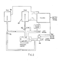
- a gaseous fuel system 10 that includes a fuel supply 12 of pressurized gaseous fuel. Gas from the supply is delivered to a regulator 14.
- the regulator has an operating component 16 controlled by a processor 18 which receives the feedback from a pressure sensor 20.
- the regulator delivers gaseous fuel at a regulated pressure to the fuel metering device 22 of a gas using device 24, for example an internal combustion engine.
- the regulator 14 includes a regulator housing 26. This has a gas inlet 28 connected to the fuel supply 12 and discharging into an inlet chamber 30 in the housing.
- the housing also has a gas outlet 32 from an outlet chamber 34 and connected to the fuel metering device 22.
- Between the inlet chamber 30 and the outlet chamber 34 is a pressure reducing valve 36.
- the pressure reducing valve 36 includes a pressure reducing valve seat 38 and a pressure reducing valve head 40 that moves towards and away from the seat to vary the size of the opening between the two, thus providing a variable restriction in the flow of gas from the inlet chamber to the outlet chamber.
- a spring 42 biases the pressure reducing valve head 40 towards engagement with the seat 38.
- a piston 44 is coupled to the pressure reducing valve head 40 and reciprocates in a cylindrical chamber 45 in the housing, separating that chamber into an outlet regulated chamber 47 on one side and a closed control chamber 46 on the other.
- a control port 48 couples the control chamber 46 to an outlet 64 of a three-way valve 50.
- the three way valve 50 includes both a feed valve having a feed valve seat 54 and a bleed valve having a bleed valve seat 56. These two valve seats cooperate with a valve body 58 having a feed valve head 60 and a bleed valve head 62 engageable with the seats 54 and 56 respectively.
- the valve body 58 thus ensures that the feed and bleed valves are operable together between a respective feed position and a respective bleed position of the three way valve 50 in which pressurised gas is either fed or bled from the control chamber 46 through the control port 48.
- the feed valve including the feed valve seat 54 and the feed valve head 60, connects the control port 48 to the pressurised supply 12 through a feed valve inlet 52 for supplying pressurised gas to the control chamber when the feed valve is opened.
- the bleed valve including the bleed valve seat 56 and the bleed valve head 62, connects the control port 48 to a bleed port 66 for bleeding pressurised gas from the control chamber when the bleed valve is opened.
- the bleed port 66 is connected to the gas outlet 32 of the regulator housing at a bleed inlet 67 as indicated in Figure 1 for bleeding the pressurised gas from the control chamber to the gas outlet of the regulator housing.
- the three way valve 50 is controlled by a solenoid operating mechanism 68 with an operating coil 69.
- the valve operates between the respective feed and bleed positions.
- the feed position the feed valve is fully open, with the head 60 disengaged from the seat 54 while the bleed valve is fully closed, with the bleed valve head 62 engaged with the valve seat 56.
- the bleed position the feed valve is fully closed by the feed valve head 60 engaging the seat 54, while the bleed valve is fully opened by the bleed valve head 62 being disengaged with the seat 56.
- the solenoid operating mechanism 68 is operated under the control of the processor 18 using a square wave signal that is pulse width modulated and/or frequency modulated to provide the desired output pressure as detected by the pressure sensor 20.
- the controller 18 has a set point input 72 for representing the desired output pressure from the regulator. This can be fixed or variable. This provides a more precise control of engine operation to meet not only fuel demand but emission standards and other parameters.
- the processor uses a proportional, integral and derivative (PID) control algorithm.
- PID proportional, integral and derivative
- the solenoid operating mechanism provides a very accurate control of the pressure in the control chamber which is balanced by the sum of the pressure in the inlet chamber 30 and the force of spring 42.
- the spring is selected to provide an adequate force to close the pressure reducing valve 36 when the outlet pressure is above the set point, or when the system is inoperative.
- FIG. 2 An alternative embodiment of the regulator is illustrated in Figure 2 , where the feed and bleed valves are operated by separate high-speed solenoid operating mechanisms.
- the feed valve 76 includes a solenoid operating mechanism 78, while the bleed valve 80 includes its own solenoid operating mechanism 82.
- This provides for independent control of the feed and bleed functions. This can be used to improve the bleed rate where the bleed valve 80 has a larger flow area. This has the additional benefit of allowing the dome to be fed, bled or held constant, reducing pressure fluctuation. In terms of hardware, the life of the solenoid operating mechanism is improved because of reduced operation.
- Both the first and second embodiments include a high pressure lock-off solenoid 86.
- the lock-off solenoid 86 is a valve, controllable between a fully open position and a fully closed position by a solenoid operating coil arranged in such a manner that the lock-off solenoid is oriented in the fully closed position when the operating coil is de-energized.
- the lock-off solenoid 86 is controlled by the controller 18 for shutting off the gaseous fuel supplied to the regulator in response to shut-off condition as determined by the controller.
- the shut-off condition comprises a shut-off signal from the controller in the event that the controller detects a failure or receives a signal from the gas using device that the gas using device is turned off.
- the high pressure lock-off solenoid 86 thus ensures that gaseous fuel is not leaked through the regulator housing when the regulator and gas using device coupled thereto are intended to be shut-off.
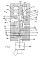
- the regulator 100 is intended for use with a gaseous fuel system 110 similar to the previously described systems of Figures 1 and 2 .
- the fuel system 110 includes a supply of pressurised gas 112 in a high pressure vessel, typically in the form of a tank, mounting an electronic regulator having an operating component 116 located in, on, or near the high pressure vessel.
- the supply 112 is mounted remotely from a gas using device 118 arranged to use the gas.
- the gas using device 118 may comprise a combustion engine, a fuel cell arrangement or any other suitable pressurised gas using device.
- Gas is delivered from the supply 112 through a pressure reducing valve within the operating component 116 of the regulator to a fuel line 120 at a regulated pressure.
- the fuel line 120 delivers the gas at the lowered regulated pressure to the fuel metering system 122 of the gas using device 118.
- a pressure sensor 124 is mounted along the fuel line 120 adjacent the fuel metering system 122 of the gas using device such that the regulator is arranged to regulate the pressure of the flow entering the metering system.
- the sensor 20 provides feedback to a processor 126 which subsequently controls the operating component 116 of the regulator.
- a housing 128 of the regulator includes a gas inlet 130 (perpendicular to the plane shown) connected directly to the fuel supply 112 for discharging into an inlet chamber 132 in the housing.
- a gas outlet 134 is also provided in the housing for discharging gas from an outlet chamber 136 in the housing to the fuel line 120 connected to the gas using device.
- a pressure reducing valve 138 is mounted between the inlet and outlet chambers to provide a variable flow restriction to the gas flowing from the inlet chamber to the outlet chamber.
- the pressure reducing valve 138 includes a pressure reducing valve seat 140 and a pressure reducing valve head 142 movable towards and away from the seat between open and closed positions to vary the size of the opening and thus vary the restriction of flow between the inlet and the outlet.
- An optional heating jacket 143 is mounted within the housing 128 to surround the pressure reducing valve 138.
- the heating jacket 143 heats the area surrounding the valve seat 140 and the inlet of the pressure reducing valve 138 to compensate for the heat which is absorbed by the gaseous fuel as it expands through the pressure reducing valve 138. This is particularly useful when regulating gaseous fuels like natural gas which absorbs a considerable amount of heat from its surroundings upon expansion.
- the pressure reducing valve head 142 is mounted on a piston 144 for sliding movement therewith within a bore 146 in the housing.
- the bore 146 defines a portion of the outlet chamber 136 surrounding the pressure reducing valve head 142.
- a counter bore 148 of greater diameter than the bore 136 defines the control chamber 150 of the regulator.
- the piston 144 is sealed with respect to the bore 146 at 152 so as to provide a seal between the control chamber 150 and the outlet chamber 136.
- the piston 144 includes a portion of increased diameter which defines a pressure responsive member 154 which divides the control chamber into a first side 156 and a second side 158.
- the pressure responsive member 154 is sealed about its periphery 160 with respect to the counter bore 148 to provide a pressure seal between the first and second sides of the pressure responsive member while remaining slidable with respect to the housing.
- Pressure is controlled in the control chamber on the first side of the pressure responsive member for controlling the position of the piston and the pressure reducing valve 138 coupled thereto.
- a port 162 extending through the piston 144 connects the outlet chamber 136 to the second side 158 of the pressure responsive member 154.
- the port 162 ensures that the back pressure on the second side of the pressure responsive member is substantially equal and balanced with the actual gas pressure at the outlet of the housing.
- a spring 164 is mounted on the second side of the pressure responsive member 154 to act in a direction corresponding to urging the pressure reducing valve head 142 to engage the valve seat 140 in a closed position of the pressure reducing valve 138.
- the spring 164 thus acts to displace the pressure responsive member 154 in the same direction as the back pressure on the second side 158 so as to be substantially balanced with the control pressure within the control chamber 150 on the first side 156 of the pressure responsive member.
- the spring is selected so as to permit a large pressure differential between the control pressure on the first side of the pressure responsive member and the outlet pressure on the second side of the pressure responsive member.
- the large pressure differential allows for rapid response time when venting the control pressure on the first side of the control chamber to the outlet chamber of the housing.
- the control pressure in the control chamber 150 is controlled by a control port 166 which is coupled to the chamber on the first side 156 of the pressure responsive member.
- the control port 166 connects the control chamber 150 to a feed valve 168 and a bleed valve 170.
- the feed valve 168 includes a feed valve head 172 which is movable with respect to a feed valve seat 174 between an open state in which the valve is fully opened and a closed state in which the valve is fully closed.
- the bleed valve 170 includes a bleed valve head 176 which is movable with respect to a bleed valve seat 178 between an open state in which the valve is fully opened and a closed state in which the valve is fully closed.
- the feed valve 168 and the bleed valve 170 are linked for operation together between a feed position in which the feed valve is in the open state and the bleed valve is in the closed state and an alternative bleed position in which the bleed valve is in the open state and the feed valve is in the closed state.
- the feed valve is coupled at an inlet to the inlet chamber 132 and at an outlet to the control port 166 of the control chamber, while the bleed valve is connected at an inlet to the control port 166 of the control chamber and at an outlet to the gas outlet 134 of the housing.
- pressurised gas is thus supplied through the control port 166 from the inlet chamber 132 to the control chamber 150 on the second side of the pressure responsive member 154.
- the increase in pressure acts to open the pressure reducing valve.
- pressurised gas from the inlet chamber 132 is prevented from entering the control port 166 and the control pressure in the control chamber 150 is thus vented through the control port 166 and subsequently through a bleed port 180 coupling the bleed valve 170 to the outlet chamber 136 of the housing.
- This acts to close the pressure reducing valve.
- a large pressure differential between the control pressure in the control chamber and the actual pressure at the outlet of the housing 128 ensures rapid response when venting.
- the feed valve 168 and the bleed valve 170 are coupled together by an actuator rod 182 which connects the valves to a high speed solenoid operating mechanism 184.
- the solenoid operating mechanism 184 is operated by the processor 126 as described in the previous embodiments using a square wave signal that is pulse width modulated and/or frequency modulated to provide the desired control pressure in the control chamber 150 to consequently provide the desired output pressure as detected by the pressure sensor 124 (as shown in Figure 3 ).
- a set point 186 is input into the processor 126 to represent the desired output pressure from the regulator.
- the set point may be varied electronically to meet the demands of the gas using device 118 through a range of performance conditions.
- the processor 126 uses a proportional integral and derivative control algorithm to control operation of the solenoid operating mechanism 184 in accordance with the set point 186.
- the pressure supplied to the metering system may be modified by modifying the set point as a means for controlling the amount of fuel injected into the engine, in addition to pulse width modulation, to extend the dynamic range of the injectors of the metering system.
- the particular arrangement of the regulator in Figure 4 also acts as a shut off valve when the solenoid operating mechanism 184 is deactivated.
- the feed and bleed valves are displaced into the bleed position thus venting the controlled pressure on the first side of the control chamber 150 to the gas outlet 134 of the housing 128 such that the control pressure on the first side of the pressure responsive member and the back pressure on the second side of the pressure responsive member are both balanced with the actual gas pressure at the gas outlet 134.
- the spring 164 thus closes the pressure reducing valve 138.
- the regulator may further be used as an integral shut off valve mounted directly on a tank of pressurized gas by selectively deactivating the solenoid operating mechanism 184 when it is desired to shut off supply from the tank.
- a high pressure lock-off solenoid 190 is provided, similarly to the previous embodiments, coupled between the supply 112 and the inlet of the regulator housing 128.
- the high pressure lock-off solenoid 190 ensures that gaseous fuel is not leaked through the regulator housing 128 when the regulator and gas using device are intended to be shut-off as described in the previous embodiments.
- the regulator housing 128 may further include a pressure relief valve to relieve excess pressure in the event that one of the operating elements or valves of the regulator fails.
- the electronic regulator described herein provides a means of controlling pressures of gaseous fuels being delivered to a gas using device such as a fuel cell or an internal combustion engine.
- the regulator is capable of providing improved pressure control for dynamic gas flow typically ranging from 0 to 20 g/s.
- the system has been designed so that fuel is not bled or purged to the atmosphere in normal operation. Further, the regulator has been designed such that a spring closes the pressure reducing valve when the system is de-energized.
- additional safety is provided by a high pressure lock-off solenoid that shuts off the gas supply to the regulator system when the electronic controller de-energizes the lock-off solenoid.
- the primary function of the controller which includes a microprocessor containing embedded software, is to control the outlet pressure to a pre-programmed set point or set function.
- the microprocessor controls on-board electronic driver circuitry which in turn controls the 12 volt high speed solenoid operating mechanism which operates the feed and bleed valves.
- the pulse width or energized time of the solenoid operating mechanism is controlled by the microprocessor using PID control and feedback from the downstream pressure transducer.
- the high speed solenoid of the solenoid operating mechanism may be frequency modulated or pulsewidth modulated to vary the ratio of energized time to de-energized time which in turn has a direct relationship on the feed to bleed ratio, thus allowing the pressure within the control volume to be manipulated resulting in a change in force on the piston/valve causing movement against the counter spring to re-establish the static force balance on the piston/valve unit.
- This movement of the piston/valve assembly is manipulated to maintain the desired output pressure despite variations in fuel demand and supply pressure.
- Tests were conducted to compare the performance of the electronic regulator with a single-stage mechanical regulator for a natural gas vehicle (NGV) fuel system. The tests were also conducted using a two-stage mechanical regulator, but those results are not included here for the sake of simplicity. The results for the two stage mechanical regulator were sufficiently similar to those for the single stage regulator that they are not considered necessary for a complete understanding of the present invention. Each regulator was set up on a test bench and tests were conducted to evaluate the following parameters:
- the electronic regulator was installed in a pickup truck equipped with a fuel injected NGV conversion system.
- the regulator replaced the single stage mechanical regulator and was tested on a chassis dynamometer. Instrumentation was installed to measure pressure and flow rate.
- the intent of the initial test is to determine the error in pressure that can occur at different flow rates as engine operation changes from idle to wide open throttle.
- the second test evaluates the change in regulator pressure as the tank pressure decreases from full to empty.
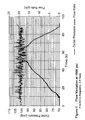
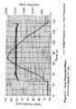
- Figures 5 and 6 compare the dynamic droop as a function of time and flow rate for the single stage mechanical regulator and the electronic regulator.
- the results for air flow rates of 20 and 10 g/s, which were scaled from Figures 7 and 8 are summarized in Table 2.
- the calculation is based on the average change in pressure, neglecting the hysteresis.
- the mechanical regulator has a droop of 22 psig (98 psig - 76 psig) for increasing flow and 20 psig (103 psig - 83 psig) for decreasing flow.
- the average droop is 21 psig. Values are also shown for a flow rate of 10 g/s.
- Table 2 Dynamic Droop Comparison Regulator Mechanical (psig) Electronic (psig) at 20 g/s 21 2 at 10 g/s 6 1
- Figures 7 and 8 were used to calculate the hysteresis for the mechanical and electronic regulators. It was calculated by scaling the difference in the outlet pressure curves at 5 g/s intervals for flow rate increasing and decreasing. The average of five points from 0 to 20 g/s was taken as the droop for the test. For example, the hysteresis for the mechanical regulator at 0, 5, 10, 15, and 20 g/s are respectively 5, 6, 7, 7, and 6 psig. And the average is 6.2 psig. The results are summarized in Table 3. Regarding the electronic regulator, the outlet pressure is noisy as shown in Figure 8 , but the hysteresis is essentially zero. Table 3: Hysteresis Comparison Regulator Single-Stage Electronic Hysteresis (psig) 6.2 0
- Cyclic variations were estimated from Figures 7 and 8 . These figures provide the best representation of the pressure variation as a function of flow rate. The results shown in Table 5 represent the noise in the outlet pressure as the flow rate is increased then decreased. A range is presented because it is difficult to establish a representative value. Cyclic variations for the mechanical regulators may be due to the spring, mass, damper effect in the fluid control system. The control chamber or "dome" of the electronic regulator is either being fed or bled at all times which results in the variability in the control pressure, and consequently the variability in the outlet pressure. The amplitude of this cyclic behaviour may be reduced through optimizing controller gains and filtering the noise in the outlet hose. Table 5: Limit-Cycle Fluctuations (psig) Regulator Single-Stage Electronic Limit Cycle ⁇ 0.5 to ⁇ 1 ⁇ 1.5 to ⁇ 5
- the maximum pressure error that might be realized in a vehicle is a function of the dynamic droop at 20 g/s, the hysteresis, and the tank pressure effect. Cyclic variations are ignored because they will be over shadowed by the pressure fluctuations caused by the fuel injectors (as mentioned later). Cracking droop for the mechanical and electronic regulators is ignored as well since this error only occurs only when a vehicle is started. As well, the transient error exhibited by the electronic regulator on a fuel flow decrease is ignored since it can be corrected. Equations I and 2 were used to calculate the maximum error and the percent maximum error; the results are summarized in Table 7. Table 7: Total Regulator Error Regulator Single-Stage Electronic Maximum Error (psig) 32 5 Percent Maximum Error 28 4
- the prototype electronic regulator was installed in a 1992 GM pickup truck with a 5.0-L engine, replacing the regulator in a natural gas fuel-injection conversion system.
- the vehicle was installed on a chassis dynamometer and driven through two test cycles: a maximum power test at wide-open throttle (WOT), and the Hot 505 part of the Federal Test Procedure (FTP-75) used to evaluate tailpipe emissions.
- WOT wide-open throttle
- FTP-75 Hot 505 part of the Federal Test Procedure
- the natural gas flow rate is shown increasing from 0.2 to 7 g/s.
- the outlet pressures from the mechanical regulator and electronic regulator are plotted on the same scale.
- the mechanical regulator has a droop ranging from about 3 to 7 psig while the electronic regulator has a droop of less than 2 psig.
- the flow rate in the Hot 505 test which ranges from about 0. 1 to 3 g/s, represents a combination of speed and load as the vehicle is accelerated and decelerated on the dynamometer.
- the mechanical regulator shows a droop of about 3 psig during transients while the electronic regulator shows essentially zero droop.
- the present invention thus provides an electronic regulator for NGV applications that is more accurate than mechanical regulators. In preferred embodiments it has the capability to set the outlet pressure on-line.
- the maximum error in the prototype electronic regulator is 4%, compared to a two-stage mechanical regulator at 18%, and a single-stage mechanical regulator at 28%. This should have a significant effect on the performance and emissions of natural gas vehicles.
- Chassis dynamometer tests in a GM pickup truck showed that the electronic regulator worked well, improving accuracy over the mechanical regulator. The tests showed that droop can be reduced to zero in the Hot 505 driving cycle.
- Bench tests demonstrate that the outlet pressure can be varied dynamically in response to given input parameters or based on elapsed time.
- An example is shown in Figure 13 in which the output pressure follows a pre-programmed ramp output.
Landscapes
- Engineering & Computer Science (AREA)
- Chemical & Material Sciences (AREA)
- Mechanical Engineering (AREA)
- General Engineering & Computer Science (AREA)
- Physics & Mathematics (AREA)
- Combustion & Propulsion (AREA)
- Fluid Mechanics (AREA)
- Chemical Kinetics & Catalysis (AREA)
- General Chemical & Material Sciences (AREA)
- Oil, Petroleum & Natural Gas (AREA)
- Automation & Control Theory (AREA)
- General Physics & Mathematics (AREA)
- Analytical Chemistry (AREA)
- Control Of Fluid Pressure (AREA)
- Glass Compositions (AREA)
- Feeding, Discharge, Calcimining, Fusing, And Gas-Generation Devices (AREA)
Claims (18)
- Régulateur de pression de gaz (14, 100) pour réguler la pression d'un gaz s'écoulant depuis une source (12, 112) du gaz sous pression vers un dispositif (24, 118) destiné à utiliser le gaz, le régulateur comprenant :un logement de régulateur (26, 128) ayant une entrée de gaz (28, 130) pour recevoir le gaz et une sortie de gaz (32, 134) pour délivrer le gaz à partir du logement ;une soupape de réduction de pression (36, 138) dans le logement pour maîtriser l'écoulement de gaz depuis l'entrée jusqu'à la sortie ; etun organe de pilotage de soupape de réduction de pression comprenant ;une chambre de pilotage (40, 150) ;une soupape d'alimentation (54, 76, 168) ayant une entrée pour recevoir le gaz et une sortie de pression de pilotage couplée à la chambre de pilotage, la soupape d'alimentation ayant un état ouvert dans lequel la soupape est totalement ouverte et un état fermé dans lequel la soupape est totalement fermée ;une soupape de purge (56, 80, 170) ayant une entrée couplée à la chambre de pilotage et une sortie pour purger le gaz à partir de celle-ci, la soupape de purge ayant un état ouvert dans lequel la soupape est totalement ouverte et un état fermé dans lequel la soupape est totalement fermée ;un mécanisme actionneur de soupapes (68, 78, 82, 184) pour actionner les soupapes d'alimentation et de purge ;un organe sensible à la pression (44, 154) dans la chambre de pilotage, l'organe sensible à la pression pouvant se déplacer en réponse à des variations d'une pression de pilotage dans la chambre de pilotage sur un premier côté (46, 156) de l'organe sensible à la pression avec lequel les soupapes d'alimentation et de purge communiquent chacune et qui est opposé à un second côté (47, 158) de l'organe sensible à la pression exposé à une contre-pression ;un mécanisme de sollicitation (42, 164) agissant sur l'organe sensible à la pression ;et un moniteur de pression (20, 124) pour surveiller une pression de gaz réelle au niveau de la sortie de gaz du logement de régulateur ;un organe de pilotage (18, 126) couplé au moniteur de pression ;caractérisé en ce que :l'entrée de la soupape d'alimentation (54, 76, 168) reçoit du gaz à partir de ladite source de gaz sous pression ;la sortie de la soupape de purge (56, 80, 170) est couplée à la sortie de gaz du logement de régulateur de telle sorte que le gaz n'est évacué que vers l'extérieur depuis le logement vers la sortie de gaz (32, 134) ;l'organe sensible à la pression (44, 154) est couplé à la soupape de réduction de pression (36, 138) pour se déplacer avec celle-ci ;la soupape de réduction de pression comprend une tête de soupape (40) montée sur l'organe sensible à la pression pour se déplacer avec celui-ci de façon coulissante ;la chambre de pilotage (45, 150) sur le second côté (47, 158) de l'organe sensible à la pression communique par l'intermédiaire d'un orifice (162) avec la sortie de gaz du logement de régulateur de telle façon que la contre-pression dans la chambre de pilotage est sensiblement maintenue à une pression de gaz réelle au niveau de la sortie de gaz du logement de régulateur ;le mécanisme de sollicitation (42, 164) agit sur l'organe sensible à la pression dans une direction correspondant à la contre-pression de telle sorte que le mécanisme de sollicitation et la contre-pression sur le second côté (47, 158) de l'organe sensible à la pression s'équilibrent avec la pression de pilotage sur le premier côté (46, 156) de l'organe sensible à la pression de façon à maintenir la pression de pilotage sensiblement supérieure à la contre-pression ;le mécanisme actionneur de soupapes (68, 78, 82, 184) comprend au moins une électrovanne à grande vitesse ; etle mécanisme actionneur de soupapes (68, 78, 82, 184) est manoeuvré par l'organe de pilotage (18, 126) qui a une pression de consigne (72, 186) et qui est couplé au mécanisme actionneur de soupapes pour piloter les manoeuvres des soupapes d'alimentation et de purge entre leurs états ouvert et fermé respectifs en réponse à une variation de la pression de gaz réelle au niveau de la sortie de gaz par rapport à la pression de consigne de telle façon que la pression de gaz réelle au niveau de la sortie de gaz est sensiblement maintenue à la pression de consigne.
- Régulateur de pression de gaz selon la revendication 1, dans lequel l'organe de pilotage (18, 126) comprend un mécanisme pour faire varier la pression de consigne de manière réglable.
- Régulateur de pression de gaz selon la revendication 1, dans lequel l'organe de pilotage (18, 126) comprend un dispositif générateur de signaux pour délivrer un signal électrique pulsé destiné à manoeuvrer la soupape d'alimentation (54, 76, 168) et la soupape de purge (56, 80, 170) et un dispositif variateur de signaux pour faire varier de façon réglable la largeur d'impulsion du signal électrique.
- Régulateur de pression de gaz selon l'une quelconque des revendications 1 à 3, dans lequel le mécanisme actionneur de soupapes (68, 78, 82, 184) comprend un mécanisme de fermeture de soupape de réduction de pression pour fermer la soupape de réduction de pression en réponse à la désactivation du mécanisme actionneur de soupapes.
- Régulateur de pression de gaz selon l'une quelconque des revendications 1 à 4, dans lequel la soupape d'alimentation (54, 76, 168) et la soupape de purge (56, 80, 170) sont couplées pour se déplacer ensemble entre une position de purge dans laquelle la soupape de purge est dans l'état ouvert et la soupape d'alimentation est dans l'état fermé et une position d'alimentation dans laquelle la soupape d'alimentation est dans l'état ouvert et la soupape de purge est dans l'état fermé.
- Régulateur de pression de gaz selon la revendication 5, dans lequel le mécanisme actionneur de soupapes (68, 78, 82, 184) comprend une électrovanne unique couplée à la soupape d'alimentation (54, 76, 108) et à la soupape de purge (56, 80, 170), les soupapes d'alimentation et de purge étant positionnées dans la position de purge lors de la désactivation de l'électrovanne unique.
- Régulateur de pression de gaz selon l'une quelconque des revendications 1 à 6, comprenant en outre une soupape d' arrêt (86, 190) couplée à l'entrée de gaz du logement de régulateur, la soupape d'arrêt étant conçue pour être fermée en réponse à une condition d' arrêt détectée par le moniteur de pression (20, 124) .
- Régulateur de pression de gaz selon la revendication 7, dans lequel la soupape d'arrêt (86, 190) comprend un mécanisme de manoeuvre à électrovanne pour déplacer la soupape entre des positions ouverte et fermée respectives, le mécanisme de manoeuvre à électrovanne étant orienté dans la position fermée lorsqu'il est désactivé.
- Régulateur de pression de gaz selon l'une quelconque des revendications 1 à 8, dans lequel l'organe de pilotage (18, 126) comprend un contrôleur électronique dans lequel la pression de consigne (72, 186) est programmable.
- Régulateur de pression de gaz selon la revendication 9, dans lequel le moniteur de pression (20, 124) comprend un transducteur de pression conçu pour générer un signal de pression de rétro-action destiné à l'organe de pilotage (18, 126).
- Régulateur de pression de gaz selon l'une quelconque des revendications 1 à 10, dans lequel l'organe de pilotage (18, 126) est un organe de pilotage électronique basé sur un processeur, qui fait varier de manière réglable un rapport du temps d'activation au temps de désactivation du mécanisme actionneur de soupapes (68, 78, 82, 184) pour faire varier de manière réglable la pression de pilotage dans la chambre de pilotage (45, 150).
- Régulateur de pression de gaz selon l'une quelconque des revendications 1 à 11, dans lequel la soupape de réduction de pression (136, 138) comprend une tête de soupape de réduction de pression (40, 142) montée sur un piston (44, 144) ayant une partie de diamètre élargi qui définit l'organe sensible à la pression (44, 154).
- Régulateur de pression de gaz selon l'une quelconque des revendications 1 à 12 en combinaison avec une réserve (12, 112) de gaz pressurisé et un dispositif utilisateur de gaz (24, 118) destiné à utiliser le gaz pressurisé, le régulateur de pression de gaz étant couplé en communication entre le dispositif utilisateur de gaz et la réserve de gaz pressurisé pour réguler la pression du gaz délivré depuis la réserve jusqu'au dispositif utilisateur de gaz.
- Combinaison selon la revendication 13, dans laquelle la réserve (12, 112) de gaz pressurisé est installée à distance du dispositif utilisateur de gaz (24, 118), relié par une conduite de gaz (120), et dans laquelle le régulateur de pression de gaz (14, 116) est installé de manière adjacente à la réserve de gaz pressurisé.
- Combinaison selon la revendication 14, dans laquelle le moniteur de pression (20, 124) est couplé à la conduite de gaz (120) de manière adjacente au dispositif utilisateur de gaz (24, 118) pour surveiller la pression de gaz réelle au niveau du dispositif utilisateur de gaz.
- Combinaison selon l'une quelconque des revendications 13 à 15, dans laquelle le dispositif utilisateur de gaz (24, 118) comprend un moteur à combustion interne.
- Combinaison selon l'une quelconque des revendications 13 à 15, dans laquelle le dispositif utilisateur de gaz (118) comprend un moteur alimenté par une pile à combustible.
- Combinaison selon l'une quelconque des revendications 13 à 17, dans laquelle l'organe de pilotage (18, 126) est conçu pour faire varier de manière réglable la pression de consigne (72, 186) en réponse à des conditions de fonctionnement variables du dispositif utilisateur de gaz (24, 118).
Applications Claiming Priority (3)
| Application Number | Priority Date | Filing Date | Title |
|---|---|---|---|
| CA002298324A CA2298324A1 (fr) | 2000-02-09 | 2000-02-09 | Regulateur de gaz electronique a volume eleve |
| CA2298324 | 2000-02-09 | ||
| PCT/CA2001/000079 WO2001059537A1 (fr) | 2000-02-09 | 2001-01-31 | Regulateur de gaz electronique a volume eleve |
Publications (2)
| Publication Number | Publication Date |
|---|---|
| EP1264228A1 EP1264228A1 (fr) | 2002-12-11 |
| EP1264228B1 true EP1264228B1 (fr) | 2010-10-13 |
Family
ID=4165287
Family Applications (1)
| Application Number | Title | Priority Date | Filing Date |
|---|---|---|---|
| EP01902189A Expired - Lifetime EP1264228B1 (fr) | 2000-02-09 | 2001-01-31 | Regulateur de gaz electronique a volume eleve |
Country Status (8)
| Country | Link |
|---|---|
| US (1) | US6758233B2 (fr) |
| EP (1) | EP1264228B1 (fr) |
| JP (1) | JP2003523008A (fr) |
| AT (1) | ATE484782T1 (fr) |
| AU (1) | AU2001229908A1 (fr) |
| CA (1) | CA2298324A1 (fr) |
| DE (1) | DE60143256D1 (fr) |
| WO (1) | WO2001059537A1 (fr) |
Families Citing this family (35)
| Publication number | Priority date | Publication date | Assignee | Title |
|---|---|---|---|---|
| US7505818B1 (en) * | 2001-09-07 | 2009-03-17 | Siemens Energy & Automation, Inc. | Converter method, system and apparatus |
| JP2004319413A (ja) * | 2003-04-21 | 2004-11-11 | Aisan Ind Co Ltd | 燃料電池システムのガス減圧装置 |
| US8037896B2 (en) | 2004-03-09 | 2011-10-18 | Mks Instruments, Inc. | Pressure regulation in remote zones |
| DE602004010490T2 (de) * | 2004-05-03 | 2008-04-30 | C.R.F. S.C.P.A. | Gaszufuhrsystem für eine Brennkraftmaschine mit einem durch einen Steuerdruck geregeltem Druckminderventil |
| ES2270329T3 (es) * | 2004-05-12 | 2007-04-01 | C.R.F. Societa Consortile Per Azioni | Sistema de alimentacion de gas para un motor de combustion interna, provisto de una valvula reductora de presion conectada al colector de admision. |
| US20060243328A1 (en) * | 2005-04-28 | 2006-11-02 | Bessmertny Raymond L | Flow control apparatus |
| US7604019B2 (en) * | 2005-07-22 | 2009-10-20 | B/E Intellectual Property | Electromechanical regulator with primary and backup modes of operation for regulating passenger oxygen |
| US7334770B2 (en) * | 2005-08-22 | 2008-02-26 | Wei-Ching Wang | Solenoid isolation valve |
| ITTO20060304A1 (it) | 2006-04-26 | 2007-10-27 | M T M S R L | Metodo e gruppo per l'alimentazione di gpl ad un motore a combustione interna |
| EP1914614B1 (fr) * | 2006-09-28 | 2012-08-15 | Taichi Inada | Soupape de régulation de pression proportionnelle |
| EP1936174B1 (fr) * | 2006-12-12 | 2008-11-26 | C.R.F. Societa Consortile per Azioni | Détendeur électronique ou unité de régulation de pression pour alimenter en gaz, en particulier du méthane ou de l'hydrogène, un moteur à combustion interne, et systèmes d'alimentation en gaz incluant cette unité |
| ITMO20070004A1 (it) * | 2007-01-11 | 2008-07-12 | Landi Renzo Spa | Regolatore di pressione |
| DE102008006567A1 (de) * | 2008-01-29 | 2009-07-30 | Robert Bosch Gmbh | Verfahren und Vorrichtung zum Einstellen eines Betriebsdruckes in einem Kraftstoffreservoir |
| US7922833B2 (en) | 2008-08-05 | 2011-04-12 | Kennametal Inc. | Gas regulator for thermal energy machining |
| WO2010146469A2 (fr) * | 2009-06-17 | 2010-12-23 | Jason Lall | Régulateur de pression électronique |
| FR2949812B1 (fr) * | 2009-09-10 | 2012-03-30 | Peugeot Citroen Automobiles Sa | Dispositif et procede de regulation de l'injection d'une quantite de reducteur en phase gaz |
| US8286652B2 (en) * | 2009-09-22 | 2012-10-16 | Eaton Corporation | Configurable active jerk control |
| JP5416676B2 (ja) * | 2010-10-19 | 2014-02-12 | 川崎重工業株式会社 | ガスエンジンの燃料ガス供給システム |
| IT1402697B1 (it) * | 2010-11-05 | 2013-09-13 | Nardi Compressori S R L | Gruppo di regolazione per rifornire utenze con gas ad alta pressione |
| CN104024469B (zh) | 2011-09-02 | 2017-05-03 | 第一太阳能有限公司 | 用于气相传输沉积系统的给料器系统和给料方法 |
| US20130118609A1 (en) * | 2011-11-12 | 2013-05-16 | Thomas Neil Horsky | Gas flow device |
| JP2014152638A (ja) * | 2013-02-05 | 2014-08-25 | Denso Corp | 内燃機関の燃料供給制御装置 |
| CA2809539C (fr) * | 2013-03-15 | 2014-05-13 | Westport Power Inc. | Prevention d'echec de regulation du carburant |
| CN103161612B (zh) * | 2013-03-29 | 2015-07-08 | 潍柴动力股份有限公司 | 一种天然气发动机供气管路的稳压装置及其稳压控制方法 |
| US9273638B2 (en) * | 2013-04-15 | 2016-03-01 | Ford Global Technologies, Llc | Variable pressure gaseous fuel regulator |
| FR3007855B1 (fr) * | 2013-06-27 | 2015-06-26 | Centre Nat Etd Spatiales | Detendeur a commande electronique |
| EP3212306B1 (fr) | 2014-10-28 | 2021-04-07 | Boehringer Ingelheim Pharma GmbH & Co. KG | Procédé de nettoyage et dispositif de commande |
| US9638348B2 (en) | 2015-05-01 | 2017-05-02 | Caterpillar Inc. | Gas flow limiter for a fuel system and process for use thereof |
| US10409298B2 (en) * | 2017-04-27 | 2019-09-10 | Marotta Controls, Inc. | Electronically controlled regulator |
| EP3654128B1 (fr) * | 2018-11-15 | 2022-06-01 | Motonic Corporation | Procédé de commande de pression de régulateur à haute pression pour empêcher une fuite interne, et vanne d'arrêt à haute pression |
| DE102019106682B4 (de) * | 2019-03-15 | 2022-07-07 | Bürkert Werke GmbH & Co. KG | Druckregler |
| CN110792516B (zh) * | 2019-09-30 | 2022-04-26 | 潍柴动力股份有限公司 | 双燃料发动机压力调节装置及具有其的双燃料发动机 |
| US11320843B2 (en) * | 2019-10-17 | 2022-05-03 | Dongguan Hesheng Machinery & Electric Co., Ltd. | Air compression system with pressure detection |
| CN110630590A (zh) * | 2019-10-18 | 2019-12-31 | 云南同巨实业有限公司 | 一种便携的压力释放阀检测台 |
| US20220196181A1 (en) * | 2020-12-23 | 2022-06-23 | Goodrich Corporation | Inflatable systems with electro-pneumatic valve modules |
Family Cites Families (17)
| Publication number | Priority date | Publication date | Assignee | Title |
|---|---|---|---|---|
| US2984251A (en) * | 1957-12-23 | 1961-05-16 | Lear Inc | Pressure regulator |
| US3455323A (en) | 1966-04-08 | 1969-07-15 | Marotta Valve Corp | Gas regulator with electronic pressure control |
| US3858598A (en) * | 1971-12-09 | 1975-01-07 | Cameron Iron Works Inc | Pressure control apparatus |
| DE3220815C2 (de) * | 1982-06-03 | 1985-02-28 | Ransburg-Gema AG, St.Gallen | Druckregelvorrichtung für gasförmige und flüssige Strömungsmittel |
| DE3221441A1 (de) | 1982-06-07 | 1983-12-08 | Robert Bosch Gmbh, 7000 Stuttgart | Gasarmatur, insbesondere fuer haushaltgeraete |
| DE3305092A1 (de) * | 1983-02-14 | 1984-08-16 | Herion-Werke Kg, 7012 Fellbach | Druckregelventil |
| JPH0426897Y2 (fr) * | 1985-12-26 | 1992-06-29 | ||
| US4766921A (en) * | 1986-10-17 | 1988-08-30 | Moog Inc. | Method of operating a PWM solenoid valve |
| JPH04125706A (ja) * | 1990-09-17 | 1992-04-27 | Ckd Corp | 圧力制御弁 |
| US5050634A (en) * | 1990-12-28 | 1991-09-24 | Hasstech, Inc. | Very low differential pressure switch |
| US5253669A (en) * | 1992-04-23 | 1993-10-19 | Span Instruments, Inc. | Controlling process gas flow |
| JPH0736551A (ja) * | 1993-07-20 | 1995-02-07 | Smc Corp | 電空レギュレータ用圧力制御装置 |
| US5474054A (en) * | 1993-12-27 | 1995-12-12 | Ford Motor Company | Fuel injection control system with compensation for pressure and temperature effects on injector performance |
| US5762102A (en) * | 1995-06-01 | 1998-06-09 | Becker Precision Equipment, Inc. | Pneumatically controlled no-bleed valve and variable pressure regulator |
| GB2316773B (en) * | 1996-06-12 | 1999-09-29 | Gas Technology Canada | Electronic gas regulator |
| DE19782256T1 (de) * | 1997-02-06 | 2000-03-16 | Smc Kk | Pneumatischer Regler |
| US6576361B1 (en) * | 2000-11-09 | 2003-06-10 | Ballard Power Systems Inc. | Method and apparatus for isolating a fuel cell assembly from its surroundings |
-
2000
- 2000-02-09 CA CA002298324A patent/CA2298324A1/fr not_active Abandoned
-
2001
- 2001-01-31 WO PCT/CA2001/000079 patent/WO2001059537A1/fr not_active Ceased
- 2001-01-31 JP JP2001558804A patent/JP2003523008A/ja active Pending
- 2001-01-31 DE DE60143256T patent/DE60143256D1/de not_active Expired - Lifetime
- 2001-01-31 AU AU2001229908A patent/AU2001229908A1/en not_active Abandoned
- 2001-01-31 AT AT01902189T patent/ATE484782T1/de not_active IP Right Cessation
- 2001-01-31 US US10/203,282 patent/US6758233B2/en not_active Expired - Lifetime
- 2001-01-31 EP EP01902189A patent/EP1264228B1/fr not_active Expired - Lifetime
Also Published As
| Publication number | Publication date |
|---|---|
| CA2298324A1 (fr) | 2001-08-09 |
| EP1264228A1 (fr) | 2002-12-11 |
| WO2001059537A1 (fr) | 2001-08-16 |
| AU2001229908A1 (en) | 2001-08-20 |
| ATE484782T1 (de) | 2010-10-15 |
| US20030168101A1 (en) | 2003-09-11 |
| DE60143256D1 (de) | 2010-11-25 |
| US6758233B2 (en) | 2004-07-06 |
| JP2003523008A (ja) | 2003-07-29 |
Similar Documents
| Publication | Publication Date | Title |
|---|---|---|
| US6758233B2 (en) | High volume electronic gas regulator | |
| US7793680B2 (en) | Electromechanical regulator with primary and backup modes of operation for regulating passenger oxygen | |
| JP5220764B2 (ja) | 気体燃料圧力調整器および気体燃料圧力調整器の利用 | |
| JP3857646B2 (ja) | ガス流調整システム | |
| US20030145890A1 (en) | Electromagnetic valve for regulation of a fuel flow | |
| US5086617A (en) | Gas turbine engine fuel control system, and metering valve | |
| US8286611B1 (en) | Electronic pressure regulator | |
| WO2012053191A1 (fr) | Système d'alimentation en combustible gazeux pour moteur à gaz | |
| US8176897B1 (en) | Electronic pressure regulator | |
| US7080503B2 (en) | Control system | |
| US8136506B1 (en) | Electronic pressure regulator | |
| EP1593832B1 (fr) | System d'alimentation pour un moteur à combustion interne avec régulateur de pression amélioré | |
| CN103765067B (zh) | 可变气体压力调节器 | |
| US4421089A (en) | Fuel metering apparatus | |
| EP1593823A1 (fr) | Systeme d'alimentation en gaz pour un moteur à combustion interne avec une vanne de réduction de pression et une electrovanne régulant la pression | |
| CN109715921B (zh) | 气体输送方法以及气体供应装置 | |
| CA2057346A1 (fr) | Appareil volumetrique pour liquides | |
| WO2014045218A1 (fr) | Dispositif régulateur de pression pour dispositifs de combustible dans des moteurs à combustion interne, en particulier pour le domaine automobile | |
| CA2368957C (fr) | Regulateur de gaz electronique a volume eleve | |
| US20140174551A1 (en) | Variable Gas Pressure Regulator | |
| JP2008175160A (ja) | ガスエンジンのベーパライザ | |
| WO2006003684A8 (fr) | Soupape multifonction servant a reguler l'alimentation d'un bruleur en gaz combustible | |
| RU2008492C1 (ru) | Система питания двигателя внутреннего сгорания | |
| JP2005188344A (ja) | ガス燃料用レギュレータ | |
| CA2922740A1 (fr) | Module de conditionnement de fluide gazeux |
Legal Events
| Date | Code | Title | Description |
|---|---|---|---|
| PUAI | Public reference made under article 153(3) epc to a published international application that has entered the european phase |
Free format text: ORIGINAL CODE: 0009012 |
|
| 17P | Request for examination filed |
Effective date: 20020906 |
|
| AK | Designated contracting states |
Kind code of ref document: A1 Designated state(s): AT BE CH CY DE DK ES FI FR GB GR IE IT LI LU MC NL PT SE TR |
|
| AX | Request for extension of the european patent |
Free format text: AL;LT;LV;MK;RO;SI |
|
| 17Q | First examination report despatched |
Effective date: 20040415 |
|
| GRAP | Despatch of communication of intention to grant a patent |
Free format text: ORIGINAL CODE: EPIDOSNIGR1 |
|
| GRAS | Grant fee paid |
Free format text: ORIGINAL CODE: EPIDOSNIGR3 |
|
| GRAA | (expected) grant |
Free format text: ORIGINAL CODE: 0009210 |
|
| AK | Designated contracting states |
Kind code of ref document: B1 Designated state(s): AT BE CH CY DE DK ES FI FR GB GR IE IT LI LU MC NL PT SE TR |
|
| REG | Reference to a national code |
Ref country code: GB Ref legal event code: FG4D |
|
| REG | Reference to a national code |
Ref country code: CH Ref legal event code: EP |
|
| REG | Reference to a national code |
Ref country code: IE Ref legal event code: FG4D |
|
| REF | Corresponds to: |
Ref document number: 60143256 Country of ref document: DE Date of ref document: 20101125 Kind code of ref document: P |
|
| REG | Reference to a national code |
Ref country code: SE Ref legal event code: TRGR |
|
| REG | Reference to a national code |
Ref country code: NL Ref legal event code: T3 |
|
| PG25 | Lapsed in a contracting state [announced via postgrant information from national office to epo] |
Ref country code: AT Free format text: LAPSE BECAUSE OF FAILURE TO SUBMIT A TRANSLATION OF THE DESCRIPTION OR TO PAY THE FEE WITHIN THE PRESCRIBED TIME-LIMIT Effective date: 20101013 Ref country code: FI Free format text: LAPSE BECAUSE OF FAILURE TO SUBMIT A TRANSLATION OF THE DESCRIPTION OR TO PAY THE FEE WITHIN THE PRESCRIBED TIME-LIMIT Effective date: 20101013 Ref country code: PT Free format text: LAPSE BECAUSE OF FAILURE TO SUBMIT A TRANSLATION OF THE DESCRIPTION OR TO PAY THE FEE WITHIN THE PRESCRIBED TIME-LIMIT Effective date: 20110214 |
|
| PG25 | Lapsed in a contracting state [announced via postgrant information from national office to epo] |
Ref country code: BE Free format text: LAPSE BECAUSE OF FAILURE TO SUBMIT A TRANSLATION OF THE DESCRIPTION OR TO PAY THE FEE WITHIN THE PRESCRIBED TIME-LIMIT Effective date: 20101013 Ref country code: GR Free format text: LAPSE BECAUSE OF FAILURE TO SUBMIT A TRANSLATION OF THE DESCRIPTION OR TO PAY THE FEE WITHIN THE PRESCRIBED TIME-LIMIT Effective date: 20110114 |
|
| PG25 | Lapsed in a contracting state [announced via postgrant information from national office to epo] |
Ref country code: ES Free format text: LAPSE BECAUSE OF FAILURE TO SUBMIT A TRANSLATION OF THE DESCRIPTION OR TO PAY THE FEE WITHIN THE PRESCRIBED TIME-LIMIT Effective date: 20110124 |
|
| PLBE | No opposition filed within time limit |
Free format text: ORIGINAL CODE: 0009261 |
|
| STAA | Information on the status of an ep patent application or granted ep patent |
Free format text: STATUS: NO OPPOSITION FILED WITHIN TIME LIMIT |
|
| PG25 | Lapsed in a contracting state [announced via postgrant information from national office to epo] |
Ref country code: DK Free format text: LAPSE BECAUSE OF FAILURE TO SUBMIT A TRANSLATION OF THE DESCRIPTION OR TO PAY THE FEE WITHIN THE PRESCRIBED TIME-LIMIT Effective date: 20101013 Ref country code: MC Free format text: LAPSE BECAUSE OF NON-PAYMENT OF DUE FEES Effective date: 20110131 |
|
| REG | Reference to a national code |
Ref country code: CH Ref legal event code: PL |
|
| 26N | No opposition filed |
Effective date: 20110714 |
|
| REG | Reference to a national code |
Ref country code: IE Ref legal event code: MM4A |
|
| PG25 | Lapsed in a contracting state [announced via postgrant information from national office to epo] |
Ref country code: CH Free format text: LAPSE BECAUSE OF NON-PAYMENT OF DUE FEES Effective date: 20110131 Ref country code: LI Free format text: LAPSE BECAUSE OF NON-PAYMENT OF DUE FEES Effective date: 20110131 |
|
| REG | Reference to a national code |
Ref country code: DE Ref legal event code: R097 Ref document number: 60143256 Country of ref document: DE Effective date: 20110714 |
|
| PG25 | Lapsed in a contracting state [announced via postgrant information from national office to epo] |
Ref country code: IE Free format text: LAPSE BECAUSE OF NON-PAYMENT OF DUE FEES Effective date: 20110131 |
|
| PG25 | Lapsed in a contracting state [announced via postgrant information from national office to epo] |
Ref country code: LU Free format text: LAPSE BECAUSE OF NON-PAYMENT OF DUE FEES Effective date: 20110131 Ref country code: CY Free format text: LAPSE BECAUSE OF FAILURE TO SUBMIT A TRANSLATION OF THE DESCRIPTION OR TO PAY THE FEE WITHIN THE PRESCRIBED TIME-LIMIT Effective date: 20101013 |
|
| PG25 | Lapsed in a contracting state [announced via postgrant information from national office to epo] |
Ref country code: TR Free format text: LAPSE BECAUSE OF FAILURE TO SUBMIT A TRANSLATION OF THE DESCRIPTION OR TO PAY THE FEE WITHIN THE PRESCRIBED TIME-LIMIT Effective date: 20101013 |
|
| REG | Reference to a national code |
Ref country code: FR Ref legal event code: PLFP Year of fee payment: 16 |
|
| REG | Reference to a national code |
Ref country code: FR Ref legal event code: PLFP Year of fee payment: 17 |
|
| REG | Reference to a national code |
Ref country code: FR Ref legal event code: PLFP Year of fee payment: 18 |
|
| PGFP | Annual fee paid to national office [announced via postgrant information from national office to epo] |
Ref country code: NL Payment date: 20200121 Year of fee payment: 20 Ref country code: GB Payment date: 20200123 Year of fee payment: 20 Ref country code: IT Payment date: 20200131 Year of fee payment: 20 Ref country code: DE Payment date: 20200121 Year of fee payment: 20 Ref country code: SE Payment date: 20200121 Year of fee payment: 20 |
|
| PGFP | Annual fee paid to national office [announced via postgrant information from national office to epo] |
Ref country code: FR Payment date: 20200121 Year of fee payment: 20 |
|
| REG | Reference to a national code |
Ref country code: DE Ref legal event code: R071 Ref document number: 60143256 Country of ref document: DE |
|
| REG | Reference to a national code |
Ref country code: NL Ref legal event code: MK Effective date: 20210130 |
|
| REG | Reference to a national code |
Ref country code: GB Ref legal event code: PE20 Expiry date: 20210130 |
|
| REG | Reference to a national code |
Ref country code: SE Ref legal event code: EUG |
|
| PG25 | Lapsed in a contracting state [announced via postgrant information from national office to epo] |
Ref country code: GB Free format text: LAPSE BECAUSE OF EXPIRATION OF PROTECTION Effective date: 20210130 |