EP1264565A2 - Dispositif de support - Google Patents
Dispositif de support Download PDFInfo
- Publication number
- EP1264565A2 EP1264565A2 EP02009831A EP02009831A EP1264565A2 EP 1264565 A2 EP1264565 A2 EP 1264565A2 EP 02009831 A EP02009831 A EP 02009831A EP 02009831 A EP02009831 A EP 02009831A EP 1264565 A2 EP1264565 A2 EP 1264565A2
- Authority
- EP
- European Patent Office
- Prior art keywords
- fastening
- holding device
- neck
- recesses
- carrier
- Prior art date
- Legal status (The legal status is an assumption and is not a legal conclusion. Google has not performed a legal analysis and makes no representation as to the accuracy of the status listed.)
- Withdrawn
Links
Images


Classifications
-
- B—PERFORMING OPERATIONS; TRANSPORTING
- B25—HAND TOOLS; PORTABLE POWER-DRIVEN TOOLS; MANIPULATORS
- B25H—WORKSHOP EQUIPMENT, e.g. FOR MARKING-OUT WORK; STORAGE MEANS FOR WORKSHOPS
- B25H3/00—Storage means or arrangements for workshops facilitating access to, or handling of, work tools or instruments
- B25H3/04—Racks
-
- F—MECHANICAL ENGINEERING; LIGHTING; HEATING; WEAPONS; BLASTING
- F16—ENGINEERING ELEMENTS AND UNITS; GENERAL MEASURES FOR PRODUCING AND MAINTAINING EFFECTIVE FUNCTIONING OF MACHINES OR INSTALLATIONS; THERMAL INSULATION IN GENERAL
- F16B—DEVICES FOR FASTENING OR SECURING CONSTRUCTIONAL ELEMENTS OR MACHINE PARTS TOGETHER, e.g. NAILS, BOLTS, CIRCLIPS, CLAMPS, CLIPS OR WEDGES; JOINTS OR JOINTING
- F16B5/00—Joining sheets or plates, e.g. panels, to one another or to strips or bars parallel to them
- F16B5/06—Joining sheets or plates, e.g. panels, to one another or to strips or bars parallel to them by means of clamps or clips
- F16B5/0607—Joining sheets or plates, e.g. panels, to one another or to strips or bars parallel to them by means of clamps or clips joining sheets or plates to each other
- F16B5/0621—Joining sheets or plates, e.g. panels, to one another or to strips or bars parallel to them by means of clamps or clips joining sheets or plates to each other in parallel relationship
- F16B2005/0671—Joining sheets or plates, e.g. panels, to one another or to strips or bars parallel to them by means of clamps or clips joining sheets or plates to each other in parallel relationship with unlocking by rotation
Definitions
- the invention relates to a holding device consisting of a fastening wall and at least one carrier that can be fastened to the latter, wherein the fastening means at least one pair of cooperating fasteners is done by a Fastening element is designed as a fastening button with a neck and the other Fastening element is a recess through which the fastening button can be pushed through and hooked into the recess with the neck, with several recesses distributed over a surface, offset in rows are arranged.
- Such holding devices are used to keep things of any kind on a mounting wall to arrange.
- These can be tools or functional elements act. The latter are then arranged in particular on such fastening walls if they are assigned to each other for experimental, teaching or installation purposes should be.
- These can be functional elements in the area of heating, Air conditioning, gas, water, ventilation, electrical or other installation technology, the Act regulation, measurement or other technology.
- a holding device of the type mentioned is from DE 94 04 972.6 U1 known.
- the object disclosed in this document has round fastening buttons that can be inserted into slightly larger round recesses.
- the recesses are in adjacent rows and with respect to two adjacent rows offset by half the grid spacing.
- Functional elements should be spatially opposite each other assigned, for example because they are connected by pipes , this requires constant consideration of the limited mounting options. Such consideration is often not possible, then adjustments are necessary connections, such as pipe connections. This is because of the required processing of the same is undesirable.
- the holding device is thus little variable. However, sufficient variability is particularly important in experimental and Teaching set-ups necessary, as these are constantly being rebuilt and often also during the Lessons need to be changed.
- the invention is therefore based on the object of a holding device at the beginning mentioned type in such a way that the variability of the arrangement of carriers in sufficient measure is guaranteed.
- the object is achieved in that the recesses in a horizontal Are elongated direction, have a straight line on the underside and the cutouts in one row are perpendicular to the cutouts in the next row Show direction of overlap areas.
- the advantage of the invention is that, depending on the length of the straight line on the underside the elongated recesses are the supports attached to the fastening wall and thus the functional elements arranged on them more or less strongly are laterally displaceable.
- the structures of the type mentioned above are more flexible make and it is possible to better match each other adapt.
- the invention facilitates the construction and saves largely constant adjustments to connectors.
- a further development provides that the dimension of the overlap areas is selected in such a way that that fasteners can be arranged among each other in all rows of recesses are.
- This is in contrast to the prior art mentioned at the beginning ensures that in each of the rows of the staggered recesses despite this staggered arrangement an exactly superimposed arrangement of Fastenings are possible. This is especially important for a mutual assignment of Functional elements are often required and it is therefore an advantage if there is a row for each of cutouts is available. By moving a beam and if necessary, moving the fastening buttons into the next recesses every assignment can be selected in the horizontal direction.
- the fastening buttons and the recesses can have any shape.
- a fastening button can be made round and the recesses have straight lines at the top and bottom and a curve at the edges, which is slightly larger than that of the fastening buttons, so that the latter can be inserted.
- the fastening button essentially is square and the recess is substantially rectangular. Are there of course, rounding at the corners is useful to prevent injuries to the buttons avoid.
- the neck of the fastening button can have a surface that corresponds to the support on the Straight line of the recess serves. This ensures better support for the wearer, especially if this is only by a fastener on the mounting wall is held.
- the Recesses, the fastening buttons and their necks have other shapes. Only the straight lines on the undersides of the recesses are necessary to create a Sliding between recesses and fastening buttons with neck to achieve.
- the attachment of a carrier to the mounting wall can be done by several pairs of Fasteners are made. Through two pairs of fasteners achieved a safe horizontal position. In doing so, a wearer can use his lower Support the end on the mounting wall, using support elements for this purpose can be arranged. Of course, there are also four or more Pairs of fasteners possible to hold a carrier securely on all sides.
- the mounting wall is grid-like arranged fastening buttons with necks and that the carrier has some recesses have to attach to the mounting wall.
- the fastening wall formed as recesses fasteners and the wearer at least one as a fastening button with a neck trained fastener is assigned.
- This configuration has the advantage that the entire surface of the carrier is available for attaching objects stands, because no fastening buttons through the recesses into this Protrude surface.
- the fastening buttons in this embodiment are in less available and the less expensive to produce recesses in large number.
- a carrier has only one fastening element because it is the easiest to attach. Then the fastener should to the center of gravity of the wearer with the attached on it Attachment wall to be attached object so that the carrier with the object moves into its target position by gravity.
- the neck has a surface which is arranged to the center of gravity of the wearer such that the surface of the neck in the rest position of the carrier rests on the straight line of a recess. To this end the neck can be square, but does not have to, since each shape with a such surface for a safe alignment of the carrier and a certain hold in the target position leads.
- a particularly advantageous embodiment provides that the fastening button is square and arranged so that its diagonals in the rest position essentially stand vertically and horizontally, with the recesses also on the top have a straight line and measure from the support of the neck on the straight line to upper tip of the fastening button is greater than the distance between the Straight lines of the cutouts.
- the carrier with the Fastening button can be inserted into a recess and then through a Quarter turn of the carrier the fastening button is placed in a position in which it is no longer removable from the recess. This position must then be the target position correspond.
- the carrier can be self-locking on the mounting wall be attached.
- This embodiment is preferably designed such that the neck is square and its surfaces to the side edges of a square fastening button form an angle ⁇ of 45 °.
- the at least one carrier at the lower part of it has a support element against the surface facing the fastening wall.
- This Support element is expediently designed such that it is in any position on the Fastening wall is present.
- it can be made larger than a recess or otherwise have a shape such that it is on the surface parts of the mounting wall always comes into contact between the recesses.
- the support element from a non-slip against the mounting wall Material exists. Then, if only one fastener is provided, then the bearer remains to help with the alignment in the target position but more secure in this position.
- the rows of recesses can thus be arranged at a greater distance be or so close together that the remaining material of the fastening wall this still gives enough stability.
- the fastening buttons can be used Carrier or mounting wall may be firmly connected or it is possible that the fastening buttons are designed to be screwed and unscrewed, for example To provide carriers with one or more fastening buttons as required. To For this purpose, a carrier can have several holes for fastening fastening buttons have with necks, for example around him optionally with one or two or four fasteners. Other different design options are of course possible, also any combination of mentioned features.
- Fig. 1 shows a first embodiment of the invention to illustrate the essential advantages of the invention. Shown is a holding device 1, which consists of a fastening wall 2 and at least one carrier 3, fastening elements 4, 4 'serving to fasten the carriers 3 to the fastening wall 2.
- the fastening wall 2 is visible from the rear, so that the support 3 hangs on the front facing away from the plane of the drawing.
- Only sectional representations are drawn through the necks 6 - fastening buttons 5 and carrier 3 must be added there.
- the carrier 3 shown has only one fastening element 4, the carrier 3 is configured with the object 24 on it, which is not visible here, that the center of gravity 13 is below the fastener 4. So will the fastening head 5 with neck 6 (first fastening element 4) in the second fastening element 4 ', which is designed as a recess 7, suspended, the moves Carrier 3 with the object 24 by the center of gravity 13 by itself in its target position.
- the recesses are arranged in rows 9 and 9 ', with rows 9' opposite the rows 9 have overlap regions 11.
- the recesses are also 7 elongated and have a straight line 10 on their underside. Therefore are on this straight line 10 the fastening buttons 5 with the necks 6 in an area 18 displaceable according to arrows 35. This ensures that the carrier 3 with the Objects 24 can be placed on the mounting wall 2 in a variable manner.
- the overlap regions 11 are expediently dimensioned such that they correspond at least to the thickness 12 of a neck 6. In this way it is possible to all rows 9 and 9 'of the recesses 7, the fasteners 4 with each other to arrange, as is the case with the three fastening elements 4, of which only the Neck 6 are shown in section, is visible.
- the mounting wall 2 are only on the surface 8 three rows 9, 9 'and 9 of recesses 7 arranged, since this is only is a small section of a mounting wall 2. In fact, it can Fastening wall 2 can be made in any size and therefore any Number of recesses 7 contained in any number of rows 9 and 9 '.
- the recesses 7 are rectangular, the corners being rounded. Therefore, there is also a straight line 15 at the upper end of the recess 7, which the Straight line 10 corresponds.
- the fastening buttons 5 are square and have a dimension that is slightly smaller than the distance between the straight lines 10 and 15. The fastening buttons 5 are also rounded at the corners. Thereby the fastening buttons 5 can be pushed through the recesses 7 and can then be hung with the neck 6 in the mounting wall 2 and as described be moved.
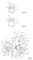
- Fig. 2 shows an embodiment with two pairs of fasteners 4 and 4 '.
- a carrier 3 is drawn in a position 19, this is the position before the carrier 3 is inserted into the fastening wall 2.
- the carrier 3 is moved in the direction of arrow 21 towards the fastening wall 2 in such a way that the buttons 5 pass through the cutouts 7 pass. Thereafter, the carrier 3 is moved a little way down, whereby the fastening elements 4 with the necks 6 hang on the recesses 7 and are secured against moving out by the fastening buttons 5.
- This position after the insertion of the fastening elements 4 shows the drawn position 20.
- FIG. 3 shows an embodiment with a single pair of fastening elements 4, 4 ', as has already been shown in FIG. 1. Because of the function of the parts with the same reference numerals, reference is made to the above statements. Further details are shown, such as the arrangement of an object 24 on the carrier 3, this object showing an installation with a pipe connection 25. The variability of the arrangement of the objects 24 is particularly advantageous for the connection of such pipelines, since the objects 24 can be variably arranged with respect to their position in accordance with the existing line pieces.
- the thickness 28 of the mounting wall 2 of the height 27 of the neck 6 must correspond or the latter can be a little bit larger, for example as Game or around the height of one arranged between the carrier 3 and the mounting wall 2 Compensating support element (not shown).
- the neck 6 of the fastening button In this embodiment, 5 has a phase 36 as an introduction and export aid as well as a Surface 16 on which ensures that it is in a stable position on the straight line 10 of the Recess 7 comes when the carrier 3 with the object 24 passes through the center of gravity 13 takes its debit position. This prevents oscillation when shaken.
- the fastening button 5 with the neck 6 is in this embodiment by means of a Screw 26 passed through a mounting hole 34 of the carrier 3 and on attached to the carrier 3, the screw 26 in a blind hole thread 29 of the fastener 4 is screwed in.
- the carrier 3 with several Fastening holes 34 for screws 26 equipped so that you can choose with one fastener 4, with two fasteners 4 or more Fasteners 4 can be equipped.
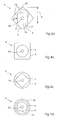
- FIG. 4a shows a fastening element 4 which can be connected to a fastening wall 2 in a self-locking manner.
- the surfaces 16 and 16 'of a square neck 6 are arranged at an angle ⁇ of 45 ° to the side edges 17 of the square button 5.
- the surface 16 of the neck 6 serves the support 32 on a straight line 10 of a recess 7.
- the dimension 14 of the surface 16 of the neck 6 serving as support 32 is dimensioned up to the tip 33 of the fastening button 5 such that it is greater than the distance 31 of the straight line 10 from the straight line 15 of the recess 7 (see FIG. 5). This achieves the self-locking which is shown in FIG. 5.
- the surfaces 16 ′ not serving as the support 32, another, for example round, configuration of the neck 6 is also possible.
- FIG. 4b shows a fastening element 4, which consists of a square fastening button 5 and a round neck 6.
- fastening button 5 is round and the neck 6 is also round, but it has a surface 16 as a bearing surface on the straight line 10, this corresponds to the fastening button 5 with neck 6, which is already shown in FIG. 3 is shown.
- a phase 36 is provided as an introduction and execution aid - the other configurations of fastening buttons 5 can also be equipped with such a phase.
- FIG. 4e shows a rectangular neck 6 (drawn as a section for better visualization), which has the same dimension 12 as the button 5 in the horizontal direction.
- FIG. 5 shows an embodiment with self-locking by means of a fastening button 5, as has already been explained in FIG. 4a.
- the carrier 3, which is to be connected to the fastening wall 2 is inclined in the plane of the carrier 3 at an angle of 45 ° to the desired position in the direction of arrow 21 towards the fastening wall 2 in order to push the fastening button 5 through the recess 7 ,
- the carrier 3 is pivoted in the direction of arrow 30 into the desired position, in which the fastening button 5 is in a position in which its diagonals are horizontal and vertical. This is the position 20 of the carrier 3 as shown.
- the dimension 14 causes the support 3 to be locked from the support of the surface 16 of the neck 6 on the straight line 10 to the tip 33 of the fastening button 5. It can no longer be removed from the fastening wall 2 by the protrusion of the tip 33 of the fastening button 5 over the straight line 15. Nevertheless, the carrier 3 can be moved according to the arrows 35.
- the height 23 of the recess 7, which corresponds to the distance between the straight lines 10 and 15, must be greater than the height 22 of the fastening button 5 so that the insertion described above is possible.
Landscapes
- Engineering & Computer Science (AREA)
- Mechanical Engineering (AREA)
- Supports Or Holders For Household Use (AREA)
- Clamps And Clips (AREA)
Applications Claiming Priority (2)
| Application Number | Priority Date | Filing Date | Title |
|---|---|---|---|
| DE10124824 | 2001-05-22 | ||
| DE2001124824 DE10124824C1 (de) | 2001-05-22 | 2001-05-22 | Haltevorrichtung |
Publications (2)
| Publication Number | Publication Date |
|---|---|
| EP1264565A2 true EP1264565A2 (fr) | 2002-12-11 |
| EP1264565A3 EP1264565A3 (fr) | 2004-01-02 |
Family
ID=7685650
Family Applications (1)
| Application Number | Title | Priority Date | Filing Date |
|---|---|---|---|
| EP02009831A Withdrawn EP1264565A3 (fr) | 2001-05-22 | 2002-05-02 | Dispositif de support |
Country Status (2)
| Country | Link |
|---|---|
| EP (1) | EP1264565A3 (fr) |
| DE (1) | DE10124824C1 (fr) |
Families Citing this family (2)
| Publication number | Priority date | Publication date | Assignee | Title |
|---|---|---|---|---|
| DE102007038623A1 (de) | 2007-08-16 | 2009-02-19 | Paul Kunkel | Modulsystem für Schulungszwecke |
| DE102010028091A1 (de) * | 2010-04-22 | 2011-10-27 | Lisa Dräxlmaier GmbH | Vorrichtung zum Festlegen eines Bauteils an einem Träger |
Family Cites Families (10)
| Publication number | Priority date | Publication date | Assignee | Title |
|---|---|---|---|---|
| DE7242342U (de) * | 1973-02-22 | Bohnacker J Kg | Platte zum Aufhangen von Korpern | |
| US3014597A (en) * | 1960-03-24 | 1961-12-26 | Miles C Mcwherter | Hanger board |
| DE1848900U (de) * | 1960-07-20 | 1962-03-22 | Robert Klein | Vorrichtung zur haengenden lagerung, insbesondere von stanzmessern u. dgl. in der schuhindustrie. |
| US3310271A (en) * | 1965-10-15 | 1967-03-21 | Leonard H King | Apertured display board and hardware therefor |
| DE2820218A1 (de) * | 1978-05-09 | 1979-11-15 | Springfix Befestigungstechnik | Befestigungselement zur loesbaren verbindung von zwei plattenartigen bauteilen |
| NL7807391A (nl) * | 1978-07-07 | 1980-01-09 | Schucom Bv | Stelsel voor het losneembaar bevestigen van voorwerpen aan een draagplaat. |
| DE3630061A1 (de) * | 1986-09-04 | 1988-03-10 | Bloksma Gmbh | Traegerplatte fuer werkstuecke, werkstuecktraeger oder -halter u.dgl. |
| DE4213559A1 (de) * | 1992-04-25 | 1993-11-04 | Heinrich Leifeld | Montageschiene |
| DE9404972U1 (de) * | 1994-03-23 | 1994-06-16 | Berthold Horstmann GmbH, 45307 Essen | Aufbauvorrichtung für Versuchs- oder Lehrzwecke |
| US6202865B1 (en) * | 1999-06-01 | 2001-03-20 | Li-Jen Kuo | Sample and tool displaying board |
-
2001
- 2001-05-22 DE DE2001124824 patent/DE10124824C1/de not_active Expired - Fee Related
-
2002
- 2002-05-02 EP EP02009831A patent/EP1264565A3/fr not_active Withdrawn
Also Published As
| Publication number | Publication date |
|---|---|
| EP1264565A3 (fr) | 2004-01-02 |
| DE10124824C1 (de) | 2002-09-12 |
Similar Documents
| Publication | Publication Date | Title |
|---|---|---|
| DE60319622T2 (de) | Ausrichtung zum Installieren einer Markise | |
| DE3924048A1 (de) | Mutterartiger kunststoffbefestiger | |
| DE3326174A1 (de) | Befestigungsvorrichtung | |
| DE102010022415A1 (de) | Montagelasche für abgehängte Decken | |
| DE3240645A1 (de) | Traggestell | |
| EP0439716A1 (fr) | Ancre pour fixer des plaques de façade sur un mur | |
| DE10236551B4 (de) | Montageteil zum temporären Halten und Fixieren | |
| DE3049346A1 (de) | Tragkonstruktion fuer unterdecken | |
| DE29808396U1 (de) | Regal | |
| DE2927803A1 (de) | System zum abnehmbaren befestigen von gegenstaenden an einer tragplatte | |
| DE10124824C1 (de) | Haltevorrichtung | |
| DE102019122106B3 (de) | Zaunerweiterungsvorrichtung | |
| DE4443743A1 (de) | Vorrichtung zum Befestigen von Fassadenplatten | |
| DE3038019A1 (de) | Aufhaengevorrichtung fuer rasterdecken mit u-foermigen lamellen | |
| EP3798379B1 (fr) | Système de profilé et système de réglage ainsi que procédé de fabrication d'un système de profilé et utilisation du système de profilé et/ou du système de réglage | |
| EP0786631A2 (fr) | Dispositif pour monter des objets, comme des radiateurs, contre un mur | |
| EP1582802B1 (fr) | Support avec dispositif de fixation pour écran plat | |
| DE202021004094U1 (de) | Zaun mit Zaunpfosten und Zaunmatten | |
| DE2342866C2 (de) | Bauelementesystem zum Aufbau von Schalttafeln | |
| DE8034595U1 (de) | Trockenrahmen zur aufnahme zu trocknender keramischer teile, insbesondere dach- und firstziegel | |
| DE3528832C2 (fr) | ||
| DE3928326C2 (de) | Befestigungskonsole für Kabelkanäle | |
| DE3401468A1 (de) | Tragvorrichtung fuer elektrische einrichtungen | |
| DE102024120920B3 (de) | Aufhängung für Pflanzmodule für einen hängenden Garten | |
| DE7225523U (de) | Bausatz für Bandrasterprofilschienen mit Kreuzverbindungsstück |
Legal Events
| Date | Code | Title | Description |
|---|---|---|---|
| PUAI | Public reference made under article 153(3) epc to a published international application that has entered the european phase |
Free format text: ORIGINAL CODE: 0009012 |
|
| AK | Designated contracting states |
Kind code of ref document: A2 Designated state(s): AT BE CH CY DE DK ES FI FR GB GR IE IT LI LU MC NL PT SE TR |
|
| AX | Request for extension of the european patent |
Free format text: AL;LT;LV;MK;RO;SI |
|
| PUAL | Search report despatched |
Free format text: ORIGINAL CODE: 0009013 |
|
| AK | Designated contracting states |
Kind code of ref document: A3 Designated state(s): AT BE CH CY DE DK ES FI FR GB GR IE IT LI LU MC NL PT SE TR |
|
| AX | Request for extension of the european patent |
Extension state: AL LT LV MK RO SI |
|
| AKX | Designation fees paid | ||
| REG | Reference to a national code |
Ref country code: DE Ref legal event code: 8566 |
|
| STAA | Information on the status of an ep patent application or granted ep patent |
Free format text: STATUS: THE APPLICATION IS DEEMED TO BE WITHDRAWN |
|
| 18D | Application deemed to be withdrawn |
Effective date: 20040703 |