EP1264657A1 - Spannvorrichtung - Google Patents
Spannvorrichtung Download PDFInfo
- Publication number
- EP1264657A1 EP1264657A1 EP02012534A EP02012534A EP1264657A1 EP 1264657 A1 EP1264657 A1 EP 1264657A1 EP 02012534 A EP02012534 A EP 02012534A EP 02012534 A EP02012534 A EP 02012534A EP 1264657 A1 EP1264657 A1 EP 1264657A1
- Authority
- EP
- European Patent Office
- Prior art keywords
- blow
- disc
- receiving
- clamping device
- clamping
- Prior art date
- Legal status (The legal status is an assumption and is not a legal conclusion. Google has not performed a legal analysis and makes no representation as to the accuracy of the status listed.)
- Granted
Links
Images


Classifications
-
- B—PERFORMING OPERATIONS; TRANSPORTING
- B23—MACHINE TOOLS; METAL-WORKING NOT OTHERWISE PROVIDED FOR
- B23Q—DETAILS, COMPONENTS, OR ACCESSORIES FOR MACHINE TOOLS, e.g. ARRANGEMENTS FOR COPYING OR CONTROLLING; MACHINE TOOLS IN GENERAL CHARACTERISED BY THE CONSTRUCTION OF PARTICULAR DETAILS OR COMPONENTS; COMBINATIONS OR ASSOCIATIONS OF METAL-WORKING MACHINES, NOT DIRECTED TO A PARTICULAR RESULT
- B23Q16/00—Equipment for precise positioning of tool or work into particular locations not otherwise provided for
-
- B—PERFORMING OPERATIONS; TRANSPORTING
- B23—MACHINE TOOLS; METAL-WORKING NOT OTHERWISE PROVIDED FOR
- B23Q—DETAILS, COMPONENTS, OR ACCESSORIES FOR MACHINE TOOLS, e.g. ARRANGEMENTS FOR COPYING OR CONTROLLING; MACHINE TOOLS IN GENERAL CHARACTERISED BY THE CONSTRUCTION OF PARTICULAR DETAILS OR COMPONENTS; COMBINATIONS OR ASSOCIATIONS OF METAL-WORKING MACHINES, NOT DIRECTED TO A PARTICULAR RESULT
- B23Q3/00—Devices holding, supporting, or positioning work or tools, of a kind normally removable from the machine
- B23Q3/18—Devices holding, supporting, or positioning work or tools, of a kind normally removable from the machine for positioning only
- B23Q3/183—Centering devices
Definitions
- the invention relates to a clamping device for positioned clamping of workpieces or tools on clamping modules that are part of a Machine table or a platen and the positioning holes have in which retractable nipples can be inserted.
- the cylinder space Seal the center hole so that no dirt particles can penetrate, not even if the retractable nipple is removed. It is also the task of Invention the surface of the recording modules also free of contamination to hold, so that an exact application of further modules, plates or To ensure workpieces.
- Clamps for fixing workpieces are u. a. in clamping modules integrated. Such clamping modules are in machine tables or Machine pallets used. Part of the clamping module 7 is a disc 1, the is provided with a central cylinder bore 2. In this cylinder bore 2 is a retractable nipple 3 is inserted, which belongs to a working device that to machining workpiece or tool. Such work devices are either plate-shaped or provided with a base that can be placed on straight surfaces. Between the clamping module and Working device is the connection of the workpiece to the machine table manufactured. Cover the dirt particles generated during the work process both the clamping module and the working device. Through the use of Cooling liquids, these particles are also suspended and penetrate everywhere. The central cylinder bore 2 is particularly affected by this.
- a locking piston 4 is provided, which with is equipped with a head plate.
- This locking piston 4 is in a blind bore 16 arranged in the clamping module 7 below the cylinder bore 2 is let in.
- This blind bore can be the diameter of the cylinder bore be aligned, or be executed differently, so that a gradation arises. It is important that the top plate of the closing piston 4 is the diameter of the Cylinder bore is adjusted.
- the closing piston 4 is in the blind bore 16 introduced that his headstock immediately below the inserted Retractable nipple 3 lies. So that the closing piston 4 closes the space below the Retractable nipple.
- the locking piston 4 can also be designed so that it also Rotation movement performed by a predetermined angle. This has the advantage that the locking piston in the extended state due to the rotary movement and simultaneous blowing freely blows the surface of the disc in a circle, so that all dirt particles are removed in a relatively large area.
- the Rotary movement can be done through appropriate compressed air channels inside the Closing piston are generated or mechanically by sliding tracks or Spindles and the like. After the surface has been blown free, the Locking piston 4 back until its head surface with the surface of the Disk 1 forms a unit. The cylinder bore 2 is thus until renewed Inserting a retractable nipple is closed and remains free of all Dirt particles. If a retractable nipple 3 is retracted, the Locking piston 4 simultaneously moved down to its starting position.
- central nozzles 13 on the upper part of the Cylinder bore 2 provided. These central nozzles 13 already produce compressed air blown into the cylinder bore at a time before the retractable nipple 3 has finally left this hole. These central nozzles 13 are expedient arranged so that their airflow is directed slightly upwards. So that will prevents dirt particles from entering the cylinder bore before the Locking piston has reached its end position. These central nozzles 13 can also can be operated independently of the locking piston.
- the locking piston 4 is below the cylinder bore 2 in the blind bore 16 of the Clamping module 7 arranged.
- a fixed part 6 is provided, in which moving parts associated with the locking piston are fitted so that they can be extended telescopically and take the locking piston with them.
- the locking piston can also be extended and retracted by rotating the thread become.
- the retraction and extension can be pneumatic, hydraulic, mechanical or done electrically.
- the disk 1 has a plurality of receiving islands 8, on which one Working device can be placed. These islands of reception are also Contaminated exposed. Any contamination of the contact surface means that a work device is not put on correctly. So they are Receiving islands 8 also to be cleaned before they are re-equipped become.
- the receiving islands holes 9 are made in the center, in which a Blow-out stamp 10 is slidably guided. This blow-out stamp 10 can Hibernation be easily drawn into the surface of the receiving island or with complete this. Becomes a working device from the receiving islands lifted out, blow out 10 extend.
- Each blow-out punch 10 is radial equipped with outward air outlet openings 11 at the upper end.
- Compressed air is blown through these air outlet openings over the surface the receiving islands is directed and blows them freely.
- a center nozzle 12 may be let into the blow-out die 10. This center nozzle then radiates upwards and achieves its effect when the working device is being lifted off. The backflow from the bottom of the working device not only flushes the receiving island freely, but also its surroundings. expedient is the underside of the working device over the effective area of the center nozzle still shaped accordingly.
- This version does not require the Extend blow-out punch 10.
- the center nozzle can also directly into the Receiving island must be inserted so that the blow-out stamp is omitted.
- FIGS. 6 There is another embodiment that is shown in FIGS. 6 is shown.
- the Support surface of the receiving islands 8 is not provided with holes, but are decentralized blow-out stamp 14 arranged directly next to each receiving island, these can be drilled directly into the disc 1, be arranged. But they can also be attached to the outside of the edge of the pane.
- the decentralized blow-out stamps are fixed in their holes so that they are retractable and retractable. In their head are radially outward directed air outlet openings 15 let in the extended state are directed directly onto the surfaces of the receiving islands 8.
- These decentralized Blow-out punches 14 can additionally or only be provided with a center nozzle 12 be that shines upwards against the underside of the working device and from there reverberates.
- These blow-out stamps have the advantage that they already during the Extending can come into action, and with that the blowing out already becomes one Time begins at which the working device has not yet taken off.
Landscapes
- Engineering & Computer Science (AREA)
- Mechanical Engineering (AREA)
- Auxiliary Devices For Machine Tools (AREA)
- Sampling And Sample Adjustment (AREA)
- Physical Vapour Deposition (AREA)
- Earth Drilling (AREA)
Abstract
Description
- Fig. 1
- zeigt eine Seitenansicht mit eingesetztem Einzugsnippel.
- Fig. 2
- zeigt die Seitenansicht ohne Einzugsnippel.
- Fig. 3
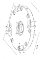
- zeigt ein Aufspannmodul.
- Fig. 4
- zeigt das Aufspannmodul mit wirksamen Ausblasdüsen.
- Fig. 5
- zeigt das Aufspannmodul mit speziellen Düsen.
- Fig. 6
- zeigt das Aufspannmodul mit ausgefahrenen speziellen Düsen.
- 1
- Scheibe
- 2
- Zylinderbohrung
- 3
- Einzugsnippel
- 4
- Schließkolben
- 5
- Austrittsdüsen
- 6
- Festteil
- 7
- Aufspannmodul
- 8
- Aufnahmeinsel
- 9
- Bohrung
- 10
- Ausblasstempel
- 11
- Luftaustrittsöffnung
- 12
- Mittendüse
- 13
- Zentraldüse
- 14
- Dezentraler Ausblasstempel
- 15
- Ausblasöffnung
- 16
- Sackbohrung
Claims (8)
- Spannvorrichtung zum positionierten Spannen von Werkstücken oder Werkzeugen auf Aufspannmodule, die in Maschinentischen oder Aufspannplatten integriert sind und die mit Positionierbohrungen in Form von Zylinderbohrungen versehen sind, in die Einzugsnippel eingesetzt werden und die mit Einrichtungen zum Ausblasen von Verunreinigungen bestückt sind, dadurch gekennzeichnet, daß eine Scheibe (1) mit mehreren Aufnahmeinseln (8) bestückt ist und mittig mit einer Zylinderbohrung (2) versehen ist, in die Einzugsnippel (3) einführbar sind, daß die Scheibe (1) mit einem Aufspannmodul (7) verbunden ist, das eine zentrale Sackbohrung (16) besitzt, die unterhalb der Zylinderbohrung (2) angeordnet ist und daß in dieser zentralen Sackbohrung (16) ein Schließkolben (4) gelagert ist, der aus der Sackbohrung heraus in die Zylinderbohrung (2) einfahrbar ist und der in seiner ausgefahrenen Endposition die Zylinderbohrung (2) mit der Oberfläche der Scheibe (1) bündig abschließt.
- Spannvorrichtung nach Anspruch 1, dadurch gekennzeichnet, daß der Schließkolben (4) eine Kopfplatte besitzt, in die radial nach außen mehrere Austrittsdüsen (5) eingelassen und mit einem Druckluftkanal verbunden sind und daß der Schließkolben (4) beim Ausfahren aus dem Zylinder in eine Stellung gebracht wird , in der seine Kopfplatte oberhalb der Kante der Zylinderbohrung liegt, daß in dieser Stellung aus den Ausblasdüsen (5) ein Luftstrom über die Oberfläche der Scheibe (1) geleitet ist und daß der Schließkolben (4) nach Beendigung des Ausblasvorganges in den Zylinderraum (2) zurückgezogen wird, bis seine Kopfplatte bündig mit der Fläche der Scheibe (1) abschließt.
- Spannvorrichtung nach Anspruch 1 und 2, dadurch gekennzeichnet, daß der Schließkolben (4) drehbar gelagert ist und während des Ausfahrens aus dem Zylinderraum (2) eine Drehbewegung um einen vorgegebenen Winkel vollführt, so daß die Ausblasdüsen (5) der Kopfplatte des Schließkolbens während des Ausblasens über die Oberfläche der Scheibe (1) schwenkbar sind.
- Spannvorrichtung nach Anspruch 1, dadurch gekennzeichnet, daß in die Zylinderbohrung (2) im oberen Bereich mehrere Zentraldüsen (13) eingelassen sind, aus denen ein leicht nach oben gerichteter Luftstrom ausblasbar ist.
- Spannvorrichtung nach Anspruch 1, dadurch gekennzeichnet, daß in die Aufnahmeinseln (8) der Scheibe (1) zentrale Bohrungen (9) eingebracht sind, in die je ein Ausblasstempel (10) gleitend geführt ist, daß der Ausblasstempel (10) kreisförmig mit Luftaustrittsöffnungen (11) versehen ist und daß der Ausblasstempel (10) aus der Aufnahmeinsel (8) ausfahrbar ist und einen Luftstrom über diese leitet.
- Ausfahren einen Luftstrom Spannvorrichtung nach Anspruch 1, dadurch gekennzeichnet, daß den Aufnahmeinseln (8) dezentrale Ausblasstempel (14) zugeordnet sind, die unmittelbar neben jeder Aufnahmeinsel der Scheibe (1) geführt sind und die mit Ausblasdüsen (15) bestückt beim über die Aufnahmeinseln leiten.
- Spannvorrichtung nach Anspruch 5 und 6, dadurch gekennzeichnet, daß der Ausblasstempel (10) und der dezentrale Ausblasstempel (14) mit einer Mittendüse (12) versehen sind, deren Luftstrom nach oben gerichtet von der Arbeitsvorrichtung im Augenblick der Abnahme umgelenkt und über die Aufnahmeinsel und deren Umgebung geleitet ist.
- Spannvorrichtung nach Anspruch 6, dadurch gekennzeichnet, daß die Ausblasstempel (14) in ihren Lage zur Aufnahmeinsel fixiert sind.
Applications Claiming Priority (2)
| Application Number | Priority Date | Filing Date | Title |
|---|---|---|---|
| DE10127207A DE10127207A1 (de) | 2001-06-05 | 2001-06-05 | Spannvorrichtung |
| DE10127207 | 2001-06-05 |
Publications (2)
| Publication Number | Publication Date |
|---|---|
| EP1264657A1 true EP1264657A1 (de) | 2002-12-11 |
| EP1264657B1 EP1264657B1 (de) | 2003-05-02 |
Family
ID=7687215
Family Applications (1)
| Application Number | Title | Priority Date | Filing Date |
|---|---|---|---|
| EP02012534A Expired - Lifetime EP1264657B1 (de) | 2001-06-05 | 2002-06-05 | Spannvorrichtung |
Country Status (3)
| Country | Link |
|---|---|
| EP (1) | EP1264657B1 (de) |
| AT (1) | ATE238879T1 (de) |
| DE (2) | DE10127207A1 (de) |
Cited By (5)
| Publication number | Priority date | Publication date | Assignee | Title |
|---|---|---|---|---|
| EP1577054A1 (de) * | 2004-03-16 | 2005-09-21 | Vischer & Bolli AG | Spannzylinder mit Verschlusskappe |
| DE202010002432U1 (de) | 2010-01-27 | 2010-06-24 | Stark Spannsysteme Gmbh | Spannvorrichtung mit einem Höhenausgleich |
| ITBO20090632A1 (it) * | 2009-10-01 | 2011-04-02 | Samp Spa Con Unico Socio | Macchina per la produzione di ingranaggi |
| DE102006043959B4 (de) * | 2006-09-14 | 2016-07-28 | Sew-Eurodrive Gmbh & Co Kg | Bearbeitungsmaschine und Verfahren |
| CN108501025A (zh) * | 2018-06-05 | 2018-09-07 | 苏州神运机器人有限公司 | 一种带吹气功能的吸盘架 |
Families Citing this family (1)
| Publication number | Priority date | Publication date | Assignee | Title |
|---|---|---|---|---|
| DE102004016820B4 (de) * | 2004-04-01 | 2011-08-18 | Stark Spannsysteme Gmbh | Schnellwechselsystem aus einem Element, insbesondere Werkstückträger, Werkzeugträger, Vorrichtung oder Werkzeug, mit einem Einzugnippel, und mit einem Schnellspannzylinder sowie Verfahren zum Spannen mittels des Schnellwechselsystems |
Citations (4)
| Publication number | Priority date | Publication date | Assignee | Title |
|---|---|---|---|---|
| DE19757430C1 (de) * | 1997-12-23 | 1999-04-29 | Vischer & Bolli Ag | Spanneinrichtung zur Fixierung eines Einzugsnippels an einer Aufspannplatte |
| EP0936025A2 (de) * | 1998-02-10 | 1999-08-18 | Stark, Emil, jr. | Spannsystem mit Spannzylinder und Aufspannteil |
| US5997011A (en) * | 1997-01-23 | 1999-12-07 | System 3R International Ab | Retaining device, in particular for a workpiece |
| DE19841928A1 (de) * | 1998-09-14 | 2000-03-16 | Emil Stark | Ausblas- und Ausspritzeinrichtung für Schnellspannzylinder mit Deckel |
-
2001
- 2001-06-05 DE DE10127207A patent/DE10127207A1/de not_active Withdrawn
-
2002
- 2002-06-05 EP EP02012534A patent/EP1264657B1/de not_active Expired - Lifetime
- 2002-06-05 AT AT02012534T patent/ATE238879T1/de active
- 2002-06-05 DE DE50200005T patent/DE50200005D1/de not_active Expired - Lifetime
Patent Citations (4)
| Publication number | Priority date | Publication date | Assignee | Title |
|---|---|---|---|---|
| US5997011A (en) * | 1997-01-23 | 1999-12-07 | System 3R International Ab | Retaining device, in particular for a workpiece |
| DE19757430C1 (de) * | 1997-12-23 | 1999-04-29 | Vischer & Bolli Ag | Spanneinrichtung zur Fixierung eines Einzugsnippels an einer Aufspannplatte |
| EP0936025A2 (de) * | 1998-02-10 | 1999-08-18 | Stark, Emil, jr. | Spannsystem mit Spannzylinder und Aufspannteil |
| DE19841928A1 (de) * | 1998-09-14 | 2000-03-16 | Emil Stark | Ausblas- und Ausspritzeinrichtung für Schnellspannzylinder mit Deckel |
Cited By (9)
| Publication number | Priority date | Publication date | Assignee | Title |
|---|---|---|---|---|
| EP1577054A1 (de) * | 2004-03-16 | 2005-09-21 | Vischer & Bolli AG | Spannzylinder mit Verschlusskappe |
| US7219886B2 (en) | 2004-03-16 | 2007-05-22 | Vischer & Bolli Ag | Clamping cylinder having a closure cap |
| DE102006043959B4 (de) * | 2006-09-14 | 2016-07-28 | Sew-Eurodrive Gmbh & Co Kg | Bearbeitungsmaschine und Verfahren |
| ITBO20090632A1 (it) * | 2009-10-01 | 2011-04-02 | Samp Spa Con Unico Socio | Macchina per la produzione di ingranaggi |
| DE202010002432U1 (de) | 2010-01-27 | 2010-06-24 | Stark Spannsysteme Gmbh | Spannvorrichtung mit einem Höhenausgleich |
| DE102010005886A1 (de) | 2010-01-27 | 2011-07-28 | Stark Spannsysteme Gmbh | Spannvorrichtung mit einem Höhenausgleich |
| EP2353774A1 (de) | 2010-01-27 | 2011-08-10 | Stark Spannsysteme GmbH | Spannvorrichtung mit einem Höhenausgleich |
| CN108501025A (zh) * | 2018-06-05 | 2018-09-07 | 苏州神运机器人有限公司 | 一种带吹气功能的吸盘架 |
| CN108501025B (zh) * | 2018-06-05 | 2023-08-18 | 苏州神运机器人有限公司 | 一种带吹气功能的吸盘架 |
Also Published As
| Publication number | Publication date |
|---|---|
| EP1264657B1 (de) | 2003-05-02 |
| DE50200005D1 (de) | 2003-06-05 |
| ATE238879T1 (de) | 2003-05-15 |
| DE10127207A1 (de) | 2002-12-12 |
Similar Documents
| Publication | Publication Date | Title |
|---|---|---|
| EP0827806B1 (de) | Spannzylinder zum Spannen eines Einzugsnippels, Einzugsnippel hierfür und Spannsystem zur Verwendung unter Späneflug | |
| DE4443421C2 (de) | Kühl- und Staubsammelvorrichtung für Werkzeugmaschine | |
| DE69026603T2 (de) | Plattenhalter in einer bohrmaschine für gedruckte schaltungen | |
| DE4442662B4 (de) | Kühl und Absaugvorrichtung für eine Werkzeugmaschine | |
| DE4037716C1 (de) | ||
| DE102006012291A1 (de) | Bohrvorrichtung zum Bohren von Löchern in Leiterplatten für elektronische Geräte, Apparate und Einrichtungen | |
| EP0970770A1 (de) | Einrichtung sowie Verfahren zur Bearbeitung von Bohrungen | |
| DE102005030397A1 (de) | Bearbeitungsvorrichtung mit Partikelbehälter | |
| DE19841928C2 (de) | Vorrichtung zur Beseitigung von Verunreinigungen an Schnellspanneinheiten | |
| CH685748A5 (de) | Kühlvorrichtung für eine Schleifmaschine. | |
| EP0445404A2 (de) | Vorrichtung zur Herstellung von Bohrlöchern mit Hinterschneidung | |
| EP1264657B1 (de) | Spannvorrichtung | |
| DE102010038035B4 (de) | Vorrichtung zur materialabtragenden Werkstückbearbeitung mit einer nach dem Bernoulli-Prinzip kontaktlos arbeitenden Werkstückhalteeinrichtung | |
| EP0522098B1 (de) | Vorrichtung zum absaugen von bearbeitungsrückständen | |
| EP1650336A1 (de) | Rundstrickmaschine mit einer Entstaubungseinrichtung | |
| DE10028579B4 (de) | Maschinentisch für eine Bearbeitungsmaschine | |
| EP0252291A2 (de) | Bearbeitungsmaschine mit einem Spindelkopf | |
| DE202015003373U1 (de) | Werkzeugschnellwechselsystem mit Späneleiteinrichtung | |
| DE4480343C2 (de) | Vorrichtung zum Ansaugen und Entfernen von Spänen für eine Werkzeugmaschine | |
| DE19613443C2 (de) | Tiefbohreinheit mit Späneauffangbehälter | |
| DE19820105C1 (de) | Einrichtung zur Reinigung des Arbeitsbereichs an Zerspanungsmaschinen | |
| EP0987082A2 (de) | Werkzeugmaschine mit einer ausserhalb des Werkstücktisches erstreckenden Werkstückeinspannvorrichtung | |
| DE10320082B4 (de) | Baueinheit zur Bearbeitung von Holztafeln | |
| DE19921071A1 (de) | Vorrichtung zur Kombination unterschiedlicher Vakuumspannsysteme zum Zwecke des gemeinsamen Betriebes | |
| DE2257653C3 (de) | Bohrkopf |
Legal Events
| Date | Code | Title | Description |
|---|---|---|---|
| PUAI | Public reference made under article 153(3) epc to a published international application that has entered the european phase |
Free format text: ORIGINAL CODE: 0009012 |
|
| GRAH | Despatch of communication of intention to grant a patent |
Free format text: ORIGINAL CODE: EPIDOS IGRA |
|
| 17P | Request for examination filed |
Effective date: 20020902 |
|
| AK | Designated contracting states |
Kind code of ref document: A1 Designated state(s): AT BE CH CY DE DK ES FI FR GB GR IE IT LI LU MC NL PT SE TR |
|
| AX | Request for extension of the european patent |
Free format text: AL;LT;LV;MK;RO;SI |
|
| GRAH | Despatch of communication of intention to grant a patent |
Free format text: ORIGINAL CODE: EPIDOS IGRA |
|
| GRAA | (expected) grant |
Free format text: ORIGINAL CODE: 0009210 |
|
| AK | Designated contracting states |
Designated state(s): AT BE CH CY DE DK ES FI FR GB GR IE IT LI LU MC NL PT SE TR |
|
| PG25 | Lapsed in a contracting state [announced via postgrant information from national office to epo] |
Ref country code: IT Free format text: LAPSE BECAUSE OF FAILURE TO SUBMIT A TRANSLATION OF THE DESCRIPTION OR TO PAY THE FEE WITHIN THE PRESCRIBED TIME-LIMIT;WARNING: LAPSES OF ITALIAN PATENTS WITH EFFECTIVE DATE BEFORE 2007 MAY HAVE OCCURRED AT ANY TIME BEFORE 2007. THE CORRECT EFFECTIVE DATE MAY BE DIFFERENT FROM THE ONE RECORDED. Effective date: 20030502 Ref country code: TR Free format text: LAPSE BECAUSE OF FAILURE TO SUBMIT A TRANSLATION OF THE DESCRIPTION OR TO PAY THE FEE WITHIN THE PRESCRIBED TIME-LIMIT Effective date: 20030502 Ref country code: IE Free format text: LAPSE BECAUSE OF FAILURE TO SUBMIT A TRANSLATION OF THE DESCRIPTION OR TO PAY THE FEE WITHIN THE PRESCRIBED TIME-LIMIT Effective date: 20030502 Ref country code: NL Free format text: LAPSE BECAUSE OF FAILURE TO SUBMIT A TRANSLATION OF THE DESCRIPTION OR TO PAY THE FEE WITHIN THE PRESCRIBED TIME-LIMIT Effective date: 20030502 Ref country code: FI Free format text: LAPSE BECAUSE OF FAILURE TO SUBMIT A TRANSLATION OF THE DESCRIPTION OR TO PAY THE FEE WITHIN THE PRESCRIBED TIME-LIMIT Effective date: 20030502 Ref country code: CY Free format text: LAPSE BECAUSE OF FAILURE TO SUBMIT A TRANSLATION OF THE DESCRIPTION OR TO PAY THE FEE WITHIN THE PRESCRIBED TIME-LIMIT Effective date: 20030502 |
|
| REG | Reference to a national code |
Ref country code: GB Ref legal event code: FG4D Free format text: NOT ENGLISH |
|
| REG | Reference to a national code |
Ref country code: CH Ref legal event code: EP |
|
| PG25 | Lapsed in a contracting state [announced via postgrant information from national office to epo] |
Ref country code: LU Free format text: LAPSE BECAUSE OF NON-PAYMENT OF DUE FEES Effective date: 20030605 |
|
| REF | Corresponds to: |
Ref document number: 50200005 Country of ref document: DE Date of ref document: 20030605 Kind code of ref document: P |
|
| REG | Reference to a national code |
Ref country code: IE Ref legal event code: FG4D Free format text: GERMAN |
|
| PG25 | Lapsed in a contracting state [announced via postgrant information from national office to epo] |
Ref country code: MC Free format text: LAPSE BECAUSE OF NON-PAYMENT OF DUE FEES Effective date: 20030630 |
|
| PG25 | Lapsed in a contracting state [announced via postgrant information from national office to epo] |
Ref country code: SE Free format text: LAPSE BECAUSE OF FAILURE TO SUBMIT A TRANSLATION OF THE DESCRIPTION OR TO PAY THE FEE WITHIN THE PRESCRIBED TIME-LIMIT Effective date: 20030802 Ref country code: DK Free format text: LAPSE BECAUSE OF FAILURE TO SUBMIT A TRANSLATION OF THE DESCRIPTION OR TO PAY THE FEE WITHIN THE PRESCRIBED TIME-LIMIT Effective date: 20030802 Ref country code: GR Free format text: LAPSE BECAUSE OF FAILURE TO SUBMIT A TRANSLATION OF THE DESCRIPTION OR TO PAY THE FEE WITHIN THE PRESCRIBED TIME-LIMIT Effective date: 20030802 |
|
| PG25 | Lapsed in a contracting state [announced via postgrant information from national office to epo] |
Ref country code: PT Free format text: LAPSE BECAUSE OF FAILURE TO SUBMIT A TRANSLATION OF THE DESCRIPTION OR TO PAY THE FEE WITHIN THE PRESCRIBED TIME-LIMIT Effective date: 20030804 |
|
| PG25 | Lapsed in a contracting state [announced via postgrant information from national office to epo] |
Ref country code: ES Free format text: LAPSE BECAUSE OF FAILURE TO SUBMIT A TRANSLATION OF THE DESCRIPTION OR TO PAY THE FEE WITHIN THE PRESCRIBED TIME-LIMIT Effective date: 20030813 |
|
| REG | Reference to a national code |
Ref country code: CH Ref legal event code: NV Representative=s name: BOVARD AG PATENTANWAELTE |
|
| AKX | Designation fees paid |
Designated state(s): AT BE CH CY DE DK ES FI FR GB GR IE IT LI LU MC NL PT SE TR |
|
| NLV1 | Nl: lapsed or annulled due to failure to fulfill the requirements of art. 29p and 29m of the patents act | ||
| GBT | Gb: translation of ep patent filed (gb section 77(6)(a)/1977) | ||
| LTIE | Lt: invalidation of european patent or patent extension |
Effective date: 20030502 |
|
| REG | Reference to a national code |
Ref country code: IE Ref legal event code: FD4D Ref document number: 1264657E Country of ref document: IE |
|
| ET | Fr: translation filed | ||
| PLBE | No opposition filed within time limit |
Free format text: ORIGINAL CODE: 0009261 |
|
| STAA | Information on the status of an ep patent application or granted ep patent |
Free format text: STATUS: NO OPPOSITION FILED WITHIN TIME LIMIT |
|
| 26N | No opposition filed |
Effective date: 20040203 |
|
| PG25 | Lapsed in a contracting state [announced via postgrant information from national office to epo] |
Ref country code: FR Free format text: LAPSE BECAUSE OF NON-PAYMENT OF DUE FEES Effective date: 20040630 Ref country code: BE Free format text: LAPSE BECAUSE OF NON-PAYMENT OF DUE FEES Effective date: 20040630 |
|
| REG | Reference to a national code |
Ref country code: FR Ref legal event code: ST |
|
| REG | Reference to a national code |
Ref country code: FR Ref legal event code: RN |
|
| REG | Reference to a national code |
Ref country code: FR Ref legal event code: FC |
|
| BERE | Be: lapsed |
Owner name: *STARK SPANNSYSTEME G.M.B.H. Effective date: 20040630 |
|
| PGFP | Annual fee paid to national office [announced via postgrant information from national office to epo] |
Ref country code: FR Payment date: 20060621 Year of fee payment: 5 |
|
| REG | Reference to a national code |
Ref country code: CH Ref legal event code: PFA Owner name: STARK SPANNSYSTEME GMBH Free format text: STARK SPANNSYSTEME GMBH#KOMMINGER STRASSE 48#6840 GOETZIS (AT) -TRANSFER TO- STARK SPANNSYSTEME GMBH#KOMMINGER STRASSE 48#6840 GOETZIS (AT) |
|
| PGFP | Annual fee paid to national office [announced via postgrant information from national office to epo] |
Ref country code: GB Payment date: 20110615 Year of fee payment: 10 |
|
| REG | Reference to a national code |
Ref country code: FR Ref legal event code: RU Effective date: 20120618 |
|
| GBPC | Gb: european patent ceased through non-payment of renewal fee |
Effective date: 20120605 |
|
| PG25 | Lapsed in a contracting state [announced via postgrant information from national office to epo] |
Ref country code: GB Free format text: LAPSE BECAUSE OF NON-PAYMENT OF DUE FEES Effective date: 20120605 |
|
| PGFP | Annual fee paid to national office [announced via postgrant information from national office to epo] |
Ref country code: CH Payment date: 20200611 Year of fee payment: 19 |
|
| PGFP | Annual fee paid to national office [announced via postgrant information from national office to epo] |
Ref country code: AT Payment date: 20200630 Year of fee payment: 19 |
|
| PGFP | Annual fee paid to national office [announced via postgrant information from national office to epo] |
Ref country code: DE Payment date: 20210611 Year of fee payment: 20 |
|
| REG | Reference to a national code |
Ref country code: CH Ref legal event code: PL |
|
| REG | Reference to a national code |
Ref country code: AT Ref legal event code: MM01 Ref document number: 238879 Country of ref document: AT Kind code of ref document: T Effective date: 20210605 |
|
| PG25 | Lapsed in a contracting state [announced via postgrant information from national office to epo] |
Ref country code: LI Free format text: LAPSE BECAUSE OF NON-PAYMENT OF DUE FEES Effective date: 20210630 Ref country code: CH Free format text: LAPSE BECAUSE OF NON-PAYMENT OF DUE FEES Effective date: 20210630 Ref country code: AT Free format text: LAPSE BECAUSE OF NON-PAYMENT OF DUE FEES Effective date: 20210605 |
|
| REG | Reference to a national code |
Ref country code: DE Ref legal event code: R071 Ref document number: 50200005 Country of ref document: DE |