EP1264745A2 - Vorrichtung zur Befestigung eines Sicherheitsgurtes - Google Patents
Vorrichtung zur Befestigung eines Sicherheitsgurtes Download PDFInfo
- Publication number
- EP1264745A2 EP1264745A2 EP02013054A EP02013054A EP1264745A2 EP 1264745 A2 EP1264745 A2 EP 1264745A2 EP 02013054 A EP02013054 A EP 02013054A EP 02013054 A EP02013054 A EP 02013054A EP 1264745 A2 EP1264745 A2 EP 1264745A2
- Authority
- EP
- European Patent Office
- Prior art keywords
- latching
- latching element
- cam
- holding part
- rail
- Prior art date
- Legal status (The legal status is an assumption and is not a legal conclusion. Google has not performed a legal analysis and makes no representation as to the accuracy of the status listed.)
- Granted
Links
- 239000002184 metal Substances 0.000 claims 2
- 238000004080 punching Methods 0.000 claims 1
- 238000010276 construction Methods 0.000 description 2
- 230000005489 elastic deformation Effects 0.000 description 2
- 238000003466 welding Methods 0.000 description 2
- 208000027418 Wounds and injury Diseases 0.000 description 1
- 230000006378 damage Effects 0.000 description 1
- 230000007423 decrease Effects 0.000 description 1
- 208000014674 injury Diseases 0.000 description 1
- 210000002239 ischium bone Anatomy 0.000 description 1
- 238000004519 manufacturing process Methods 0.000 description 1
Images

Classifications
-
- B—PERFORMING OPERATIONS; TRANSPORTING
- B60—VEHICLES IN GENERAL
- B60R—VEHICLES, VEHICLE FITTINGS, OR VEHICLE PARTS, NOT OTHERWISE PROVIDED FOR
- B60R22/00—Safety belts or body harnesses in vehicles
- B60R22/18—Anchoring devices
- B60R22/26—Anchoring devices secured to the seat
-
- B—PERFORMING OPERATIONS; TRANSPORTING
- B60—VEHICLES IN GENERAL
- B60R—VEHICLES, VEHICLE FITTINGS, OR VEHICLE PARTS, NOT OTHERWISE PROVIDED FOR
- B60R22/00—Safety belts or body harnesses in vehicles
- B60R22/18—Anchoring devices
- B60R2022/1806—Anchoring devices for buckles
Definitions
- the invention relates to a device for fastening a seat belt according to the Preamble of claim 1.
- the invention has for its object to generic devices in particular To optimize for manufacturability in mass production.
- the deformation element one associated with the fulcrum Bearing sleeve and a pivot lever holding the bearing sleeve as a pre-assembly kit educated.
- the deformation member for the swivel lever advantageously acts like a Pivot bearing and is at least together with this to a pre-assembly kit summarized. It can be used for captive fastening of the deformation member this, for example, on the pivot lever itself or on the pivot lever associated vulcanized.
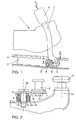
- FIG. 1 shows a side view of a vehicle seat 1 shown in sections. This is longitudinally adjustable along a guide rail 2 via a roller 3 (see FIG. 3) or by means of a sliding shoe which is also usually used.
- An integral part of the guide rail 2 is a latching rail 4, which is designed here as a sawtooth, in which a latching element 5, here designed like a cam, can be locked when a predetermined belt force F G is applied to a belt buckle 6, which is fastened on a holding part 7, during full braking or during an accident situation is exceeded.
- Further essential components of the device are a pivot lever 8, a deformation member 9, and a holding pocket 10 (see also FIG. 2).
- the latter is attached to a bearing block 11 which is assigned to a rear seat leg 12 and is embodied here as an integral part thereof.
- the holding pocket designed here as the first polygonal profile in the manner of a square pot is fastened to the bearing block 11, for example by CO 2 welding or projection welding.
- This square pot receives the correspondingly profiled deformation member 9 (see also FIGS. 8, 9).
- a likewise square-contoured bearing sleeve 14 is fitted as the second polygonal profile, which in turn is firmly connected to the pivot lever 8 in the manner of an engagement piece and has a through hole 15 on the inside. This is penetrated by a fastening screw 16.
- a further fastening screw 17 is screwed into a thread 18 (see FIGS.
- the latching element 5 has a first cam engagement section 19, which can be locked in the locking rail 4, and a second cam engagement section 20, which is smaller in comparison, and which is positively fitted into a correspondingly contoured recess 21 of the pivot lever 8 (see FIGS. 4 and 5).
- a circumferential retaining flange 22 prevents it from being unscrewed from the locking rail 2 attached to the vehicle, in particular with a view to limiting the transverse movements. In this way it is also prevented that the holding part 7 can perform tilting movements around the pivot lever 8.
- the view in FIG. 3 also shows that the latching element 5 which can be inserted into the recess 21 is arranged between a pivot point located within the holding pocket 10 and a rear seat leg 12.
- the holding part 7 (see FIG. 1) is designed in such a way that the belt force F G is directed in a typical load case so that its line of action essentially runs through the latching element 5.
- a deformation member 9 made, for example, of rubber
- the latching element 5 is automatically disengaged again from the latching rail 4 when the belt load decreases. This then results in a rest position, which enables problem-free longitudinal adjustment of the vehicle seat 1 within the guide rail 2.
- the roller 3 is still a pressure roller 23 assigned, which in a second holding pocket 24 also with no further here Deformation member shown is mounted.
- This further deformation element and also the Holding bag 23 can according to a particularly advantageous development of the invention be constructed identically, so that for both functions inexpensive identical Individual parts can be manufactured.
- the storage of the pivot lever 8 by means of the elastic deformation member 9 is to be regarded as particularly advantageous here since it is easy to produce small parts without large assembly effort, a pivot point for the locking element 5 can be realized.
- a pre-assembly kit can be formed.
- the locking element 5 and the holding part 7 together with the belt buckle 6 can also be assigned. This Relatively large component range is then completely screwed to the bearing block 11 or ischium 12 attached.
- bearing sleeve 14 and deformation member 9 can for example here preferably metallic components by directly vulcanizing them firmly together connect.
- the holding pocket 10 can then be fastened by means of a fastening screw 16 the bearing block 11 can be tensioned.
- the pivot lever 8 is so on the bearing sleeve 14 attached that it is easily accessible.
- the pivot lever 8 has a rotating one Holding flange 25, which is rounded in a foot area not further numbered here and can be handled by the assembly personnel without risk of injury.
Landscapes
- Engineering & Computer Science (AREA)
- Mechanical Engineering (AREA)
- Automotive Seat Belt Assembly (AREA)
- Braking Arrangements (AREA)
Abstract
Description
- Figur 1:
- in einer Seitenansicht wesentliche Elemente der erfindungsgemäßen Vorrichtung,
- Figur 2:
- eine Ansicht gemäß Schnitt II - II in Figur 1,
- Figur 3:
- eine perspektivische Ansicht für ein Fahrzeugsitzgestell, an dem die erfindungsgemäße Vorrichtung befestigt ist,
- Figuren 4/5:
- einen Schwenkhebel in unterschiedlichen Ansichten,
- Figuren 6/7:
- ein Rastelement in unterschiedlichen Ansichten,
- Figuren 8/9:
- ein elastisches Deformationsglied in unterschiedlichen Ansichten.
Claims (11)
- Vorrichtung zur Befestigung eines Sicherheitsgurtes an einem längs- und/oder höhenverstellbaren Fahrzeugsitz mitdadurch gekennzeichnet, dasseinem Halteteil (7) zur Aufnahme eines dem Sicherheitsgurt zugeordneten Funktionsteils (6),einem in einer fahrzeugfesten Rastschiene (4) verrastbaren Rastelement (5), das am Fahrzeugsitz (1) zumindest mittelbar schwenkbar angelenkt und über das Halteteil (7) betätigbar ist,einem Deformationsglied (9), das unter Einwirkung einer am Halteteil (7) eingeleiteten Gurtkraft nachgiebig ist, und welches in einer Ruhestellung das Rastelement (5) gegenüber der Rastschiene (4) außer Eingriff hält und bei Überschreitung einer vorgegebenen Gurtkraft zur Verrastung des Rastelementes (5) in der Rastschiene (4) nachgibt,
das Deformationsglied (9), eine dem Drehpunkt zugeordnete Lagerhülse (14) und ein die Lagerhülse (14) haltender Schwenkhebel (8) als Vormontagesatz ausgebildet sind. - Vorrichtung nach Anspruch 1, dadurch gekennzeichnet, dass das Rastelement (5) nockenförmig ausgebildet ist.
- Vorrichtung nach Anspruch 1 oder Anspruch 2, dadurch gekennzeichnet, dass das Rastelement (5) dem Halteteil (7) zugeordnet ist.
- Vorrichtung nach wenigstens einem der Ansprüche 1 bis 3, dadurch gekennzeichnet, dass das Rastelement (5) dem Schwenkhebel (8) zugeordnet ist.
- Vorrichtung nach Anspruch 4, dadurch gekennzeichnet, dass an dem Schwenkhebel (8) eine das Rastelement (5) formschlüssig aufnehmende Ausnehmung (21) vorgesehen ist.
- Vorrichtung nach einem der Ansprüche 1 bis 5, dadurch gekennzeichnet, dass an dem Halteteil (7) eine das Rastelement (5) formschlüssig aufnehmende Ausnehmung (21) vorgesehen ist.
- Vorrichtung nach einem der Ansprüche 2 bis 6, dadurch gekennzeichnet, dass an dem nockenförmigen Rastelement (5) ein erster Nockeneingriffsabschnitt (19) für die Rastschiene (4) und ein zweiter Nockeneingriffsabschnitt (20) zur Unterbringung in einer das Rastelement (5) formschlüssig aufnehmenden Ausnehmung (21) vorgesehen ist.
- Vorrichtung nach einem der Ansprüche 2 bis 7, dadurch gekennzeichnet, dass das nockenförmige Rastelement (5) von einer Gewindebohrung (18) durchsetzt ist.
- Vorrichtung nach einem der Ansprüche 2 bis 8, dadurch gekennzeichnet, dass an dem nockenförmigen Rastelement (5) ein umlaufender Halteflansch (22) angeformt ist, der ebenfalls eine Nockenkontur aufweist.
- Vorrichtung nach wenigstens einem der Ansprüche 1 bis 9, dadurch gekennzeichnet, dass der Schwenkhebel (8) ein Blechformteil mit einem aufgestellten Rand (25) ist, der umlaufend ausgeführt und im Fußbereich gerundet ist.
- Vorrichtung nach Anspruch 10, dadurch gekennzeichnet, dass zur formschlüssigen Aufnahme des Rastelementes (5) und/oder von Elementen des Drehpunkts (14) durch Stanzung erzeugt Ausnehmungen in dem Blechformteil (8) vorgesehen sind.
Applications Claiming Priority (3)
| Application Number | Priority Date | Filing Date | Title |
|---|---|---|---|
| DE19627914 | 1996-07-11 | ||
| DE19627914 | 1996-07-11 | ||
| EP97110111A EP0818371B1 (de) | 1996-07-11 | 1997-06-20 | Vorrichtung zur Befestigung eines Sicherheitsgurtes |
Related Parent Applications (1)
| Application Number | Title | Priority Date | Filing Date |
|---|---|---|---|
| EP97110111.8 Division | 1997-06-20 |
Publications (3)
| Publication Number | Publication Date |
|---|---|
| EP1264745A2 true EP1264745A2 (de) | 2002-12-11 |
| EP1264745A3 EP1264745A3 (de) | 2003-01-15 |
| EP1264745B1 EP1264745B1 (de) | 2005-08-10 |
Family
ID=7799521
Family Applications (3)
| Application Number | Title | Priority Date | Filing Date |
|---|---|---|---|
| EP02013054A Expired - Lifetime EP1264745B1 (de) | 1996-07-11 | 1997-06-20 | Vorrichtung zur Befestigung eines Sicherheitsgurtes |
| EP02013053A Expired - Lifetime EP1264744B1 (de) | 1996-07-11 | 1997-06-20 | Vorrichtung zur Befestigung eines Sicherheitsgurtes |
| EP97110111A Expired - Lifetime EP0818371B1 (de) | 1996-07-11 | 1997-06-20 | Vorrichtung zur Befestigung eines Sicherheitsgurtes |
Family Applications After (2)
| Application Number | Title | Priority Date | Filing Date |
|---|---|---|---|
| EP02013053A Expired - Lifetime EP1264744B1 (de) | 1996-07-11 | 1997-06-20 | Vorrichtung zur Befestigung eines Sicherheitsgurtes |
| EP97110111A Expired - Lifetime EP0818371B1 (de) | 1996-07-11 | 1997-06-20 | Vorrichtung zur Befestigung eines Sicherheitsgurtes |
Country Status (5)
| Country | Link |
|---|---|
| US (1) | US5924773A (de) |
| EP (3) | EP1264745B1 (de) |
| CN (1) | CN1082468C (de) |
| DE (3) | DE59712391D1 (de) |
| ES (2) | ES2194138T3 (de) |
Cited By (1)
| Publication number | Priority date | Publication date | Assignee | Title |
|---|---|---|---|---|
| CN104228756A (zh) * | 2013-06-20 | 2014-12-24 | 丰田纺织株式会社 | 交通工具用座椅的制造方法 |
Families Citing this family (6)
| Publication number | Priority date | Publication date | Assignee | Title |
|---|---|---|---|---|
| DE19740043B4 (de) * | 1997-09-12 | 2007-02-01 | C. Rob. Hammerstein Gmbh & Co. Kg | Fahrzeugsitz mit einem höhenverstellbaren Untergestell und einem am Sitzträger befestigten Gurtschloß |
| US6260926B1 (en) | 2000-02-28 | 2001-07-17 | Leonard James Meraw | Energy absorbing webbing for seat belt systems |
| DE10235086B4 (de) * | 2002-07-31 | 2009-10-29 | Johnson Controls Gmbh | Sicherheitseinrichtung für Fahrzeugsitze |
| DE102007041000B4 (de) * | 2006-09-13 | 2009-07-16 | C. Rob. Hammerstein Gmbh & Co. Kg | Kraftfahrzeug mit einem Untergestell, einem Sicherheitsgurt und einem Gurtautomaten |
| DE102007023074A1 (de) | 2007-05-16 | 2008-11-20 | Volkswagen Ag | Fahrzeugsitz mit einer Sitzfläche, einer klappbaren Sitzlehne und einem Gurtschloss |
| DE102007045340A1 (de) | 2007-09-22 | 2009-04-02 | Daimler Ag | Kraftfahrzeugsitz |
Citations (2)
| Publication number | Priority date | Publication date | Assignee | Title |
|---|---|---|---|---|
| DE2742668A1 (de) | 1977-09-22 | 1979-03-29 | Opel Adam Ag | Sicherheitsgurtbefestigung |
| DE3829824A1 (de) | 1987-09-16 | 1989-03-30 | Volkswagen Ag | Sicherheitsgurt-befestigungsvorrichtung |
Family Cites Families (5)
| Publication number | Priority date | Publication date | Assignee | Title |
|---|---|---|---|---|
| DE2802617C2 (de) * | 1978-01-21 | 1985-01-10 | Keiper Automobiltechnik Gmbh & Co Kg, 5630 Remscheid | Verankerung für Gurtschlösser |
| DE2853263A1 (de) * | 1978-12-09 | 1980-06-19 | Keiper Automobiltechnik Gmbh | Verankerung fuer gurtschloesser von in fahrzeugen angeordneten sicherheitsgurten |
| IT7953821U1 (it) * | 1979-12-19 | 1981-06-19 | Gilardini Spa | Dispositivo di bloccaggio di una estremita' di una cintura di sicurezza per autoveicoli, rispetto ad una guida di scorrimento di un sedile. |
| US4923214A (en) * | 1989-01-26 | 1990-05-08 | Hoover Universal, Inc. | Seat belt anchorage |
| JPH0315248U (de) * | 1989-06-28 | 1991-02-15 |
-
1997
- 1997-06-20 ES ES97110111T patent/ES2194138T3/es not_active Expired - Lifetime
- 1997-06-20 EP EP02013054A patent/EP1264745B1/de not_active Expired - Lifetime
- 1997-06-20 DE DE59712391T patent/DE59712391D1/de not_active Expired - Lifetime
- 1997-06-20 EP EP02013053A patent/EP1264744B1/de not_active Expired - Lifetime
- 1997-06-20 EP EP97110111A patent/EP0818371B1/de not_active Expired - Lifetime
- 1997-06-20 DE DE59709541T patent/DE59709541D1/de not_active Expired - Lifetime
- 1997-06-20 DE DE59712389T patent/DE59712389D1/de not_active Expired - Lifetime
- 1997-06-20 ES ES02013053T patent/ES2243623T3/es not_active Expired - Lifetime
- 1997-07-11 CN CN97114509A patent/CN1082468C/zh not_active Expired - Fee Related
- 1997-07-11 US US08/893,845 patent/US5924773A/en not_active Expired - Lifetime
Patent Citations (2)
| Publication number | Priority date | Publication date | Assignee | Title |
|---|---|---|---|---|
| DE2742668A1 (de) | 1977-09-22 | 1979-03-29 | Opel Adam Ag | Sicherheitsgurtbefestigung |
| DE3829824A1 (de) | 1987-09-16 | 1989-03-30 | Volkswagen Ag | Sicherheitsgurt-befestigungsvorrichtung |
Cited By (3)
| Publication number | Priority date | Publication date | Assignee | Title |
|---|---|---|---|---|
| CN104228756A (zh) * | 2013-06-20 | 2014-12-24 | 丰田纺织株式会社 | 交通工具用座椅的制造方法 |
| US9573505B2 (en) | 2013-06-20 | 2017-02-21 | Toyota Boshoku Kabushiki Kaisha | Manufacturing method for vehicle seat |
| CN104228756B (zh) * | 2013-06-20 | 2018-07-03 | 丰田纺织株式会社 | 交通工具用座椅的制造方法 |
Also Published As
| Publication number | Publication date |
|---|---|
| EP1264744B1 (de) | 2005-08-10 |
| DE59712389D1 (de) | 2005-09-15 |
| DE59712391D1 (de) | 2005-09-15 |
| EP1264745B1 (de) | 2005-08-10 |
| EP0818371A1 (de) | 1998-01-14 |
| EP1264745A3 (de) | 2003-01-15 |
| EP1264744A3 (de) | 2003-01-15 |
| EP1264744A2 (de) | 2002-12-11 |
| ES2243623T3 (es) | 2005-12-01 |
| CN1172744A (zh) | 1998-02-11 |
| ES2194138T3 (es) | 2003-11-16 |
| US5924773A (en) | 1999-07-20 |
| EP0818371B1 (de) | 2003-03-19 |
| CN1082468C (zh) | 2002-04-10 |
| DE59709541D1 (de) | 2003-04-24 |
Similar Documents
| Publication | Publication Date | Title |
|---|---|---|
| EP1343662B1 (de) | Vorrichtung zur lagerung eines pedalhebels eines kraftfahrzeuges | |
| DE19651092A1 (de) | Sicherheitsgurtvorrichtung für ein Fahrzeug | |
| EP1838561B1 (de) | Höhenverstellbare umlenkvorrichtung für einen dreipunktgurt, fahrzeugsitz mit einem dreipunktgurt sowie verfahren zur höhenverstellung des oberen haltepunktes eines dreipunktgurtes | |
| EP1329367A1 (de) | Fahrzeuginsassen-Rückhaltesystem | |
| DE69502142T2 (de) | Vorrichtung zum Schnellverbinden eines Kindersitzes mit einem Kraftwagensitz | |
| DE3519322A1 (de) | Vorrichtung zur befestigung eines kindersitzes auf einem fahrzeugsitz mittels eines normalen dreipunkt-automatik-sicherheitsgurtsystems | |
| EP1264745B1 (de) | Vorrichtung zur Befestigung eines Sicherheitsgurtes | |
| EP0300470A1 (de) | Vorrichtung zum Ankoppeln des mit dem Gurtschloss eines Sicherheitsgurtes versehenen Tragstücks an ein fahrzeugfestes Halteteil | |
| EP0472773A1 (de) | Befestigung eines schwenkbaren Verankerungsbeschlages in einem Sicherheitsgurtsystem | |
| WO2021004848A1 (de) | Gurtschloss, gurtschlosssystem und flugzeugsicherheitsgurt | |
| DE2819018A1 (de) | Schloss fuer sicherheitsgurte fuer fahrzeuge | |
| DE10206780A1 (de) | Befestigungsvorrichtung für einen Kindersitz | |
| DE69509481T2 (de) | Vorrichtung zum Verankern eines Kraftfahrzeug-Sicherheitsgurtendes | |
| DE102009034584A1 (de) | Befestigungseinrichtung für einen Gurtbandumlenker | |
| DE19581585C2 (de) | Sicherheitsgurtaufroller mit Gurtband-Klemmvorrichtung | |
| DE102011110642A1 (de) | Beschlagbaugruppe | |
| DE8816665U1 (de) | Höhenverstellvorrichtung für einen Beschlag eines Sicherheitsgurt-Rückhaltesystems in Kraftfahrzeugen | |
| DE102008007856B4 (de) | Befestigungsvorrichtung für ein an einem gegenüber einer Sitzschiene längs- und/oder höhenverstellbaren Fahrzeugsitz angeordnetes Sicherheitsgurtschloß | |
| DE3029127A1 (de) | Geradlinig fuehrende verstellschiene | |
| DE69407355T2 (de) | Verankerungsvorrichtung für Sicherheitsgurte | |
| DE102021207883B3 (de) | Trägersystem für ein Zweirad | |
| DE102023104996B3 (de) | Kraftfahrzeug mit einem Sitz und einer Sicherheitsgurtanordnung | |
| DE102021208622B4 (de) | Gurtsystem für ein Fahrzeug | |
| DE1057476B (de) | Ausloeseeinrichtung fuer die Anschnallgurte in Kraftfahrzeugen | |
| DE3126868A1 (de) | Sicherheitsgurteinrichtung fuer fahrzeuge, insbesondere kraftfahrzeuge |
Legal Events
| Date | Code | Title | Description |
|---|---|---|---|
| PUAI | Public reference made under article 153(3) epc to a published international application that has entered the european phase |
Free format text: ORIGINAL CODE: 0009012 |
|
| PUAL | Search report despatched |
Free format text: ORIGINAL CODE: 0009013 |
|
| AC | Divisional application: reference to earlier application |
Ref document number: 818371 Country of ref document: EP |
|
| AK | Designated contracting states |
Kind code of ref document: A2 Designated state(s): DE ES FR GB IT |
|
| AK | Designated contracting states |
Kind code of ref document: A3 Designated state(s): DE ES FR GB IT |
|
| 17P | Request for examination filed |
Effective date: 20030715 |
|
| AKX | Designation fees paid |
Designated state(s): DE ES FR GB IT |
|
| GRAP | Despatch of communication of intention to grant a patent |
Free format text: ORIGINAL CODE: EPIDOSNIGR1 |
|
| GRAS | Grant fee paid |
Free format text: ORIGINAL CODE: EPIDOSNIGR3 |
|
| GRAA | (expected) grant |
Free format text: ORIGINAL CODE: 0009210 |
|
| AC | Divisional application: reference to earlier application |
Ref document number: 0818371 Country of ref document: EP Kind code of ref document: P |
|
| AK | Designated contracting states |
Kind code of ref document: B1 Designated state(s): DE ES FR GB IT |
|
| PG25 | Lapsed in a contracting state [announced via postgrant information from national office to epo] |
Ref country code: IT Free format text: LAPSE BECAUSE OF FAILURE TO SUBMIT A TRANSLATION OF THE DESCRIPTION OR TO PAY THE FEE WITHIN THE PRESCRIBED TIME-LIMIT;WARNING: LAPSES OF ITALIAN PATENTS WITH EFFECTIVE DATE BEFORE 2007 MAY HAVE OCCURRED AT ANY TIME BEFORE 2007. THE CORRECT EFFECTIVE DATE MAY BE DIFFERENT FROM THE ONE RECORDED. Effective date: 20050810 Ref country code: GB Free format text: LAPSE BECAUSE OF FAILURE TO SUBMIT A TRANSLATION OF THE DESCRIPTION OR TO PAY THE FEE WITHIN THE PRESCRIBED TIME-LIMIT Effective date: 20050810 |
|
| REG | Reference to a national code |
Ref country code: GB Ref legal event code: FG4D Free format text: NOT ENGLISH |
|
| REF | Corresponds to: |
Ref document number: 59712391 Country of ref document: DE Date of ref document: 20050915 Kind code of ref document: P |
|
| PG25 | Lapsed in a contracting state [announced via postgrant information from national office to epo] |
Ref country code: ES Free format text: LAPSE BECAUSE OF FAILURE TO SUBMIT A TRANSLATION OF THE DESCRIPTION OR TO PAY THE FEE WITHIN THE PRESCRIBED TIME-LIMIT Effective date: 20051121 |
|
| GBV | Gb: ep patent (uk) treated as always having been void in accordance with gb section 77(7)/1977 [no translation filed] |
Effective date: 20050810 |
|
| PLBE | No opposition filed within time limit |
Free format text: ORIGINAL CODE: 0009261 |
|
| STAA | Information on the status of an ep patent application or granted ep patent |
Free format text: STATUS: NO OPPOSITION FILED WITHIN TIME LIMIT |
|
| 26N | No opposition filed |
Effective date: 20060511 |
|
| PG25 | Lapsed in a contracting state [announced via postgrant information from national office to epo] |
Ref country code: FR Free format text: LAPSE BECAUSE OF FAILURE TO SUBMIT A TRANSLATION OF THE DESCRIPTION OR TO PAY THE FEE WITHIN THE PRESCRIBED TIME-LIMIT Effective date: 20060811 |
|
| EN | Fr: translation not filed | ||
| PG25 | Lapsed in a contracting state [announced via postgrant information from national office to epo] |
Ref country code: FR Free format text: LAPSE BECAUSE OF FAILURE TO SUBMIT A TRANSLATION OF THE DESCRIPTION OR TO PAY THE FEE WITHIN THE PRESCRIBED TIME-LIMIT Effective date: 20050810 |
|
| PGFP | Annual fee paid to national office [announced via postgrant information from national office to epo] |
Ref country code: DE Payment date: 20130630 Year of fee payment: 17 |
|
| REG | Reference to a national code |
Ref country code: DE Ref legal event code: R119 Ref document number: 59712391 Country of ref document: DE |
|
| REG | Reference to a national code |
Ref country code: DE Ref legal event code: R119 Ref document number: 59712391 Country of ref document: DE Effective date: 20150101 |
|
| PG25 | Lapsed in a contracting state [announced via postgrant information from national office to epo] |
Ref country code: DE Free format text: LAPSE BECAUSE OF NON-PAYMENT OF DUE FEES Effective date: 20150101 |