EP1264948A2 - Verriegelbarer Türgriff mit eingebautem Kombinationsschloss - Google Patents
Verriegelbarer Türgriff mit eingebautem Kombinationsschloss Download PDFInfo
- Publication number
- EP1264948A2 EP1264948A2 EP02253842A EP02253842A EP1264948A2 EP 1264948 A2 EP1264948 A2 EP 1264948A2 EP 02253842 A EP02253842 A EP 02253842A EP 02253842 A EP02253842 A EP 02253842A EP 1264948 A2 EP1264948 A2 EP 1264948A2
- Authority
- EP
- European Patent Office
- Prior art keywords
- door
- base body
- door handle
- locking
- combination lock
- Prior art date
- Legal status (The legal status is an assumption and is not a legal conclusion. Google has not performed a legal analysis and makes no representation as to the accuracy of the status listed.)
- Granted
Links
Images














Classifications
-
- E—FIXED CONSTRUCTIONS
- E05—LOCKS; KEYS; WINDOW OR DOOR FITTINGS; SAFES
- E05B—LOCKS; ACCESSORIES THEREFOR; HANDCUFFS
- E05B13/00—Devices preventing the key or the handle or both from being used
- E05B13/10—Devices preventing the key or the handle or both from being used formed by a lock arranged in the handle
- E05B13/103—Combination lock
-
- E—FIXED CONSTRUCTIONS
- E05—LOCKS; KEYS; WINDOW OR DOOR FITTINGS; SAFES
- E05B—LOCKS; ACCESSORIES THEREFOR; HANDCUFFS
- E05B1/00—Knobs or handles for wings; Knobs, handles, or press buttons for locks or latches on wings
- E05B1/0092—Moving otherwise than only rectilinearly or only rotatively
-
- E—FIXED CONSTRUCTIONS
- E05—LOCKS; KEYS; WINDOW OR DOOR FITTINGS; SAFES
- E05B—LOCKS; ACCESSORIES THEREFOR; HANDCUFFS
- E05B37/00—Permutation or combination locks; Puzzle locks
- E05B37/02—Permutation or combination locks; Puzzle locks with tumbler discs or rings arranged on a single axis, each disc being adjustable independently of the others
-
- E—FIXED CONSTRUCTIONS
- E05—LOCKS; KEYS; WINDOW OR DOOR FITTINGS; SAFES
- E05C—BOLTS OR FASTENING DEVICES FOR WINGS, SPECIALLY FOR DOORS OR WINDOWS
- E05C9/00—Arrangements of simultaneously actuated bolts or other securing devices at well-separated positions on the same wing
- E05C9/02—Arrangements of simultaneously actuated bolts or other securing devices at well-separated positions on the same wing with one sliding bar for fastening when moved in one direction and unfastening when moved in opposite direction; with two sliding bars moved in the same direction when fastening or unfastening
- E05C9/021—Arrangements of simultaneously actuated bolts or other securing devices at well-separated positions on the same wing with one sliding bar for fastening when moved in one direction and unfastening when moved in opposite direction; with two sliding bars moved in the same direction when fastening or unfastening with rack and pinion mechanism
-
- Y—GENERAL TAGGING OF NEW TECHNOLOGICAL DEVELOPMENTS; GENERAL TAGGING OF CROSS-SECTIONAL TECHNOLOGIES SPANNING OVER SEVERAL SECTIONS OF THE IPC; TECHNICAL SUBJECTS COVERED BY FORMER USPC CROSS-REFERENCE ART COLLECTIONS [XRACs] AND DIGESTS
- Y10—TECHNICAL SUBJECTS COVERED BY FORMER USPC
- Y10S—TECHNICAL SUBJECTS COVERED BY FORMER USPC CROSS-REFERENCE ART COLLECTIONS [XRACs] AND DIGESTS
- Y10S292/00—Closure fasteners
- Y10S292/31—Lever operator, flush
-
- Y—GENERAL TAGGING OF NEW TECHNOLOGICAL DEVELOPMENTS; GENERAL TAGGING OF CROSS-SECTIONAL TECHNOLOGIES SPANNING OVER SEVERAL SECTIONS OF THE IPC; TECHNICAL SUBJECTS COVERED BY FORMER USPC CROSS-REFERENCE ART COLLECTIONS [XRACs] AND DIGESTS
- Y10—TECHNICAL SUBJECTS COVERED BY FORMER USPC
- Y10T—TECHNICAL SUBJECTS COVERED BY FORMER US CLASSIFICATION
- Y10T292/00—Closure fasteners
- Y10T292/57—Operators with knobs or handles
-
- Y—GENERAL TAGGING OF NEW TECHNOLOGICAL DEVELOPMENTS; GENERAL TAGGING OF CROSS-SECTIONAL TECHNOLOGIES SPANNING OVER SEVERAL SECTIONS OF THE IPC; TECHNICAL SUBJECTS COVERED BY FORMER USPC CROSS-REFERENCE ART COLLECTIONS [XRACs] AND DIGESTS
- Y10—TECHNICAL SUBJECTS COVERED BY FORMER USPC
- Y10T—TECHNICAL SUBJECTS COVERED BY FORMER US CLASSIFICATION
- Y10T70/00—Locks
- Y10T70/50—Special application
- Y10T70/5611—For control and machine elements
- Y10T70/5757—Handle, handwheel or knob
- Y10T70/5761—Retractable or flush handle
-
- Y—GENERAL TAGGING OF NEW TECHNOLOGICAL DEVELOPMENTS; GENERAL TAGGING OF CROSS-SECTIONAL TECHNOLOGIES SPANNING OVER SEVERAL SECTIONS OF THE IPC; TECHNICAL SUBJECTS COVERED BY FORMER USPC CROSS-REFERENCE ART COLLECTIONS [XRACs] AND DIGESTS
- Y10—TECHNICAL SUBJECTS COVERED BY FORMER USPC
- Y10T—TECHNICAL SUBJECTS COVERED BY FORMER US CLASSIFICATION
- Y10T70/00—Locks
- Y10T70/50—Special application
- Y10T70/5611—For control and machine elements
- Y10T70/5757—Handle, handwheel or knob
- Y10T70/5765—Rotary or swinging
- Y10T70/577—Locked stationary
-
- Y—GENERAL TAGGING OF NEW TECHNOLOGICAL DEVELOPMENTS; GENERAL TAGGING OF CROSS-SECTIONAL TECHNOLOGIES SPANNING OVER SEVERAL SECTIONS OF THE IPC; TECHNICAL SUBJECTS COVERED BY FORMER USPC CROSS-REFERENCE ART COLLECTIONS [XRACs] AND DIGESTS
- Y10—TECHNICAL SUBJECTS COVERED BY FORMER USPC
- Y10T—TECHNICAL SUBJECTS COVERED BY FORMER US CLASSIFICATION
- Y10T70/00—Locks
- Y10T70/50—Special application
- Y10T70/5611—For control and machine elements
- Y10T70/5757—Handle, handwheel or knob
- Y10T70/5765—Rotary or swinging
- Y10T70/577—Locked stationary
- Y10T70/5783—Combination lock
-
- Y—GENERAL TAGGING OF NEW TECHNOLOGICAL DEVELOPMENTS; GENERAL TAGGING OF CROSS-SECTIONAL TECHNOLOGIES SPANNING OVER SEVERAL SECTIONS OF THE IPC; TECHNICAL SUBJECTS COVERED BY FORMER USPC CROSS-REFERENCE ART COLLECTIONS [XRACs] AND DIGESTS
- Y10—TECHNICAL SUBJECTS COVERED BY FORMER USPC
- Y10T—TECHNICAL SUBJECTS COVERED BY FORMER US CLASSIFICATION
- Y10T70/00—Locks
- Y10T70/70—Operating mechanism
- Y10T70/7153—Combination
- Y10T70/7181—Tumbler type
- Y10T70/7198—Single tumbler set
- Y10T70/7237—Rotary or swinging tumblers
- Y10T70/726—Individually set
- Y10T70/7271—Associated movable operator
- Y10T70/7288—Spindle operator
- Y10T70/7299—Axially shiftable spindle
-
- Y—GENERAL TAGGING OF NEW TECHNOLOGICAL DEVELOPMENTS; GENERAL TAGGING OF CROSS-SECTIONAL TECHNOLOGIES SPANNING OVER SEVERAL SECTIONS OF THE IPC; TECHNICAL SUBJECTS COVERED BY FORMER USPC CROSS-REFERENCE ART COLLECTIONS [XRACs] AND DIGESTS
- Y10—TECHNICAL SUBJECTS COVERED BY FORMER USPC
- Y10T—TECHNICAL SUBJECTS COVERED BY FORMER US CLASSIFICATION
- Y10T70/00—Locks
- Y10T70/70—Operating mechanism
- Y10T70/7153—Combination
- Y10T70/7181—Tumbler type
- Y10T70/7198—Single tumbler set
- Y10T70/7237—Rotary or swinging tumblers
- Y10T70/726—Individually set
- Y10T70/7305—Manually operable
Definitions
- the present invention relates to a door locking handle assembly with a built-in combination lock of the pull-out and side-swinging lever-action type, in which a door handle is pivoted to a base body of the assembly so as to be pulled out forward and pushed back rearward relative to the base body and turned on its pivoted end.
- a door locking handle assembly of a conventional type shown in U.S. Patent No.5,467,623, herein incorporated by reference has a construction in which: a base body of the assembly is fixedly mounted on a door; a door handle is pivoted to the base body so as to be pulled out forward and pushed back rearward relative to the base body and further turned sideward on its pivoted end after completion of its pulling-out operation; when the door handle is pulled out of the base body to assume its pulled-up or raised inclination position relative to the base body or turned sideward after completion of its pulling-out operation, a catch plate or rack which serves as a door bolt directly or indirectly connected with the door handle is released from a receiving portion of a stationary frame element (i.e., door frame for supporting a door).
- a cylinder lock is incorporated in either the door handle or the base body. On the other hand, the door handle is pushed back rearward relative to the base body and held in its folded or locked
- the present invention was made. Consequently, it is an object of the present invention to provide a door locking handle assembly, which is small in thickness as a whole and capable of providing a very large number of available keys of a combination lock incorporated in the assembly, wherein a large number of eligible persons or users of various instruments contained in a box or container provided with the door locking handle assembly are precisely controlled through a computerized personal management system.
- a control operator of the instruments housed in the box allocates to each of a large number of eligible users or owners of these instruments a unique combination of marks of the marked dial discs of the combination lock for unlocking and locking the combination lock.
- each of the eligible users In opening a door of the box to use the instruments contained in the box, it is necessary for each of the eligible users to establish his or her own allocated unique combination of the marks by turning in a normal or a reverse direction each of the marked dial discs a given number of times, wherein the marks are provided in an outer peripheral surface of each of the dial discs.
- the combination lock is unlocked to permit the locking member and the lower-end end latch member connected with the lower end portion of the locking member to move to their unlocked positions, so that the door handle is released from the base body, which permits the door handle is pulled out of the base body to assume its raised position.
- the rack which is slidably supported and guided in the door latch mechanism of the door, is moved up and down relative to the door latch mechanism and engaged with and disengaged from the receiving portion of the stationary frame element of the box, which permits the door of the box to be closed and opened, respectively.
- a base body 1 of the door locking handle assembly is fixedly mounted on a front surface of a door 2, which is provided with a mounting hole 3.
- the door 2 is swingably supported by a stationary frame element or door frame (not shown) such as a box containing various types of instruments therein. More specifically, as shown in Fig.
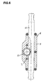
- a screw 7 is inserted into a through-hole 8 of a fastening casing 5 from its rear side, passes through this fastening casing 5 forward, and is then threadably engaged with a threaded hole 6 formed in a rear portion of the base body 1, so that a door 2 is firmly sandwiched between the base body 1 and the fastening casing 5.
- the fastening casing 5 is combined with a rack 12 to form a door latch mechanism 4, wherein the rack 12 is slidably supported and guided to serve as a door bolt for the door 2.
- a bearing hole 9 is formed in an upper portion of the base body 1 to extend in a direction perpendicular to a front surface of the door 2.
- a locking shaft 10 Rotatably received in such a bearing hole 9 of the base body 1 in an insertion manner is a locking shaft 10.
- the locking shaft 10 is provided with a shoulder portion in its substantially intermediate portion. This intermediate shoulder portion of the locking shaft 10 prevents the locking shaft 10 from axially sliding relative to the base body 1.
- the locking shaft 10 is provided with a square hole 10a in its rear portion. Fixedly received in such a square hole 10a of the locking shaft 10 in an insertion manner is a corresponding square column portion formed in a front end portion of a pinion shaft 11.
- a pinion shaft 11 Fixedly received in such a square hole 10a of the locking shaft 10 in an insertion manner is a corresponding square column portion formed in a front end portion of a pinion shaft 11.
- the pinion shaft 11 is provided with a pinion gear formed in an outer peripheral surface of its rear end portion. Such a pinion gear of the pinion shaft 11 meshes with a rack 12.
- the rack 12 serves as a door bolt for the door 2.
- the rack 12 is slidably supported and guided in the door latch mechanism 4 of the door 2, and capable of moving up and down relative to the door latch mechanism 4 so as to be engaged with and disengaged from a receiving portion "3" of a stationary frame element "2" of a box containing the various types of instruments therein, which permits the door "1" of the box to be opened, wherein: the reference numerals "3", “2” and “1”enclosed in double quotation marks are used in the prior art: U.S. Patent No.5,467,623, herein incorporated by reference.
- a concave portion 14 formed in an upper rear portion of the door handle 13 is a concave portion 14.
- the concave portion 14 assumes a substantially fan-like shape in longitudinal section to swingably receive therein a front end portion of the locking shaft 10. More specifically, the door handle 13 has its upper end portion corresponding to its concave portion 14 pivoted to the front end portion of the locking shaft 10 through a cross pivot 15.
- the cross pivot 15 extends in parallel with a front surface of the door 2 in a direction perpendicular to the longitudinal axis of the door handle 13. In operation, when the door handle 13 is folded down so as to be embedded in the base body 1, it is possible for a front concave portion 16 of the base body 1 to receive therein a rear portion of an essential part of the door handle 13.
- a flange serving as a fingertip engaging edge portion 17, which bulges out sideward in a direction perpendicular to the longitudinal axis of the door handle 13.
- both the fingertip engaging edge portions 17 of the door handle 13 are still spaced apart forward from a front surface of the corresponding lower portion of the base body 1, which enables the user to pick up the lower free end portion of the door handle 13 in an easy manner.
- the locking shaft 10 has its rear end portion coaxially fixed to a pinion shaft 11.
- the pinion shaft 11 is provided with a pinion gear in an outer peripheral surface of its rear end portion. Due to the above construction, the locking shaft 10 thus rotated together with the door handle 13 rotatably drives the pinion shaft 11 so as to rotate the pinion gear of the pinion shaft 11. As shown in Fig.
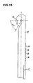
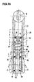
- an elongated hollow portion 20 (shown in Fig. 5) for receiving therein a combination lock 19.
- the hollow portion 20 of the door handle 13 is open at the rear side of the door handle 13 to form an opening which is covered by a back plate member 21.
- the combination lock 19 is constructed from a plurality of components.
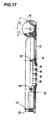
- Essential components of the combination lock 19 are: a plurality of marked dial discs 22; a plurality of cam discs 23 combined with the dial discs 22; a rod-shaped locking member 24; and, a lower-end latch member 35 connected with a lower end portion of the locking member 24 for preventing the door handle 13 from being pulled out of the base body 1.
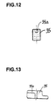
- a lower end portion of the locking member 24 is bent to form a lower-end bent portion which is inserted in a bent recess 35a (shown in Fig. 7) of the lower-end latch member 35, so that the locking member 24 is connected with the lower-end latch member 35.
- each of the cam discs 23 assumes a short cylindrical shape, and is provided with a through-hole 23a which extends in a direction perpendicular to the paper of Fig. 50 to axially passes through a center of the cam disc 23.
- the locking member 24 passes through the through-hole 23a of the cam disc 23.
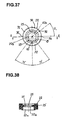
- each of the marked dial discs 22 is provided with a small-diameter bore portion 22a and a large-diameter bore portion 22b. These bore portions 22a, 22b are combined with each other to form a through-hole, which axially passes through a center of each of the dial discs 22.
- a spring member 27 is constructed of a compression coil spring to exert its resilient force on the uppermost one of the cam discs 23.
- this cam disc 23 has an interlocking projection 26 of its outer peripheral surface engaged with an interlocking groove 25 of an inner peripheral surface of the small-diameter bore portion 22a of the corresponding dial disc 22.
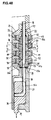
- the cam disc 23 has its lower portion extend downward from the small-diameter bore portion 22a of the corresponding dial disc 22 under the effect of the resilient force exerted by the spring member 27. Consequently, as is clear from Fig. 48, in this locked condition of operation, the interlocking projection 26 (shown in Fig. 44) of the cam disc 23 is disengaged from the interlocking groove 25 (shown in Fig. 38) of the corresponding dial disc 22.
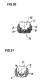
- the cam disc 23 is provided with a plurality of positioning projections 26a in its outer peripheral surface.
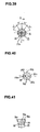
- the number of these positioning projections 26a is equal to the number of a plurality of marks having been applied to an outer peripheral surface of the dial disc 22. These marks are denoted by the Roman numerals, for example such as "4", "3", "2", as shown in Fig. 36, and spaced apart from each other at predetermined equal angular intervals.
- the positioning projection 26a of the cam disc 23 is formed in a proximal end portion of the interlocking projection 26.
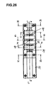
- the back plate member 21 is fixedly mounded on the inner surface of the door handle 13 by means of a plurality of screws 30 (shown in Fig. 7), each of which screws 30 is threadably engaged with a threaded hole 29 (shown in Fig. 23) of each of a plurality of guide projections 28.
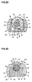
- the back plate member 21 is provided with at least one positioning groove 31, which is engaged with at least one of the positioning projections 26a of the cam disc 23 (shown in Fig. 41).
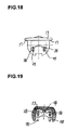
- a plurality of detent grooves 32 are formed in an outer peripheral surface of the dial disc 22 at predetermined equal angular intervals in a manner such that each of the detent grooves 32 is sandwiched between adjacent ones of the marks having been applied to the outer peripheral surface of the dial disc 22. Consequently, the number of the detent grooves 32 is equal to that of the marks applied to the outer peripheral surface of the dial disc 22.
- a detent leaf spring 33 is fixedly mounted in the elongated hollow portion 20 of the door handle 13 to have its free end portion detachably engaged with each of the detent grooves 32 of the dial disc 22. This enables each of the dial discs 22 to be held in its predetermined angular position, and therefore to establish a unique combination of the marks of the dial discs 22.
- the locking member 24 has its lower end portion engaged with the lower-end latch member 35, which makes it possible to move up the lowermost one of the cam discs 23 against the resilient force exerted by the coil spring member 27 when the lower-end latch member 35 is moved up into the hollow portion 36 of the door handle 13.
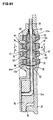
- an upper end portion of the cam disc 23 enters the small-diameter bore portion 22a of the dial disc 22 (Fig. 51), so that the positioning projection 26a of the cam disc 23 is axially moved up out of the positioning groove 31 (shown in Fig. 34) of the back plate member 21.
- the interlocking projection 26 of the cam disc 23 (shown in Figs. 41 to 43) is engaged with the corresponding interlocking groove 25 of the dial disc 22 (shown in Figs. 36 to 38).
- the cam disc 23 is interlocked with the corresponding dial disc 22. Consequently, under such circumstances, when the dial disc 22 is turned through a predetermined angle by the user, the cam disc 23 is also turned through the same predetermined angle.
- the coil spring member 27 drives the cam disc 23 downward to force the upper end portion of the cam disc 23 to separate from the small-diameter bore portion 22a of the corresponding dial disc 22. As a result, only the dial disc 22 thus separated from the corresponding cam disc 23 become rotatable.
- the interlocking grooves 25 of the dial discs 22 align in angular position with the corresponding interlocking projections 26 of the cam discs 23 to receive these projections 26 therein, so that the combination lock 19 is unlocked.
- a plurality of the cam discs 23 are vertically stacked into a neat pile between the coil spring member 27 and the interlocking ring 37 in a manner such that such a neat pile of the cam discs 23 are resiliently urged against the interlocking ring 37 under the effect of a resilient force exerted by the coil spring member 27 which is mounted over an upper end portion of the locking member 24.
- the dial disc 22 is so arranged as to have a part thereof extended forward (as shown in Figs. 1 and 2) from a slot 38 formed in the front surface of the door handle 13.
- each of the marks of the dial discs 22 is constructed of a predetermined numeric character, for example such as any one of numerals from "0" to "9". These marks or numerals are angularly spaced apart from each other at predetermined equal angular intervals.
- the locking member 24 passes through the though-holes 23a formed in the centers of the cam discs 23.
- the lower-end latch member 35 connected with the lower end portion of the locking member 24, it is also possible to make the lower-end latch member 35 an integral part of the locking member 24.
- the lower-end latch member 35 extends out of the hollow portion 36 of the door handle 13 through its lower-end opening 39 to engage with the projection portion 40 of the base body 1, wherein the projection portion 40 assumes substantially a triangular shape in cross section.
- the projection portion 40 of the base body 1 is provided with a front cam slope 42 and a rear cam slope 41.
- the interlocking groove 25 of the dial disc 22 is aligned in angular position with the interlocking projection 26 of the cam disc 23 to receive therein the interlocking projection 26 of the cam disc 23 when the cam disc 23 is moved upward in Fig. 51, which permits the combination lock 19 to be unlocked.
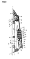
- a time when the door handle 13 is released from the base body 1 is a time when the lower-end latch member 35 is pushed upward to reach its uppermost position shown in Fig. 7.
- the door handle 13 is further pulled up or swung forward through a predetermined angle, as shown in Fig. 8.
- the door handle 13 is turned on the locking shaft 10 through a predetermined angle in a direction perpendicular to the paper of Fig. 8, so that the rack 12 of the door 2 is retracted from a stationary frame element of the box, wherein such a stationary frame element is disclosed in the prior art: Patent No.5,467,623, herein incorporated by reference.
- the door 2 is unlocked from the stationary frame element of the box.
- the door locking handle system of the present invention is capable of permitting, through its computerized personal management system, a plurality of persons or users to have easily and quickly access to their instruments contained in the box provided with the door locking handle assembly of the present invention.
- Each of the eligible users is capable of unlocking the combination lock 19 of the door locking handle assembly by turning in a normal or a reverse direction each of the marked dial discs 22 a given number of times to establish the unique combination having been allocated to each user, wherein the marks are provided in an outer peripheral surface of each of the dial discs 22.
- the combination lock 19 is capable of moving to its unlocking position.
- the locking member 24 or the lower-end latch member 35 connected with the lower end portion of the locking member 24 is released from its restricted condition and capable of moving to its unlocking position. Due to this, the door handle 13 is released from the base body 1 of the door locking handle assembly to move to its pulled-up or inclined position.
- the lower-end latch member 35 which is connected with the lower end portion of the locking member 24 and brought into press-contact with the rear cam slope 41 of the projection portion 40 of the base body 1, is pushed upward against the resilient force, which is exerted by the coil spring member 27 on the lower-end latch member 35 through the locking member 24, to permit the lower-end latch member 35 to be disengaged from the rear cam slope 41 projection portion 40 of the base body 1.
- the user it is possible for the user to turn the door handle 13 forward through a predetermined angle up to its pulled-up or raised position.
- the rack 12 serving as a door bolt for the door 2 is slidably moved downward relative to the door 2 and therefore disengaged from the receiving portion of the stationary frame element such as the main body of the box, which permits the door 2 of the box to be opened.
- the locking member 24 is so arranged as to pass through the central through-hole 22a, 22b of each of the dial discs 22 of the combination lock 19 and to extend in parallel with the longitudinal axis of the door handle 13, it is possible for the door handle 13 to remarkably reduce its thickness as a whole in construction, which permits the height of the door locking handle assembly of the present invention from the front surface of the door 2 to the front surface of the door handle 13 of the assembly to be the lowest possible level.
- the lower-end latch member 35 connected with the lower end portion of the locking member 24 is detachably engaged with the projection portion 40 of the base body 1; both the dial discs 22 and the locking member 24 including the lower-end latch member 35 connected therewith are resiliently urged downward by means of the coil spring member 27; and the projection portion 40 of the base body 1 is provided with the rear cam slope 41 for driving the lower-end latch member 35 upward against a resilient force exerted by the spring member 27 when the door handle 13 is pulled out of the base body 1 after the combination lock 19 is unlocked. Due to the above construction, in the door locking handle assembly of the present invention, there is little need to construct a means for driving the locking member 24 with separate components. This enables the door locking handle assembly of the present invention to considerably reduce the number of its components, and therefore considerably simplify its construction and reduce the manufacturing cost to a large extent.
Landscapes
- Lock And Its Accessories (AREA)
- Patch Boards (AREA)
- Packaging For Recording Disks (AREA)
Applications Claiming Priority (2)
| Application Number | Priority Date | Filing Date | Title |
|---|---|---|---|
| JP2001173589A JP3583383B2 (ja) | 2001-06-08 | 2001-06-08 | 符号合わせ錠組込み型扉用ロックハンドル装置 |
| JP2001173589 | 2001-06-08 |
Publications (3)
| Publication Number | Publication Date |
|---|---|
| EP1264948A2 true EP1264948A2 (de) | 2002-12-11 |
| EP1264948A3 EP1264948A3 (de) | 2004-04-14 |
| EP1264948B1 EP1264948B1 (de) | 2005-03-02 |
Family
ID=19015026
Family Applications (1)
| Application Number | Title | Priority Date | Filing Date |
|---|---|---|---|
| EP02253842A Expired - Lifetime EP1264948B1 (de) | 2001-06-08 | 2002-05-31 | Verriegelbarer Türgriff mit eingebautem Kombinationsschloss |
Country Status (5)
| Country | Link |
|---|---|
| US (1) | US6564598B2 (de) |
| EP (1) | EP1264948B1 (de) |
| JP (1) | JP3583383B2 (de) |
| AT (1) | ATE290145T1 (de) |
| DE (1) | DE60203067T2 (de) |
Families Citing this family (7)
| Publication number | Priority date | Publication date | Assignee | Title |
|---|---|---|---|---|
| JP2002266528A (ja) * | 2001-03-07 | 2002-09-18 | Takigen Mfg Co Ltd | 扉用ロックハンドル装置 |
| DE20319136U1 (de) * | 2003-12-10 | 2005-04-28 | Dirak Konstruktionselemente Gmbh & Co. Kg | Verschluß zur Mehrfachverriegelung von Türen oder Wandteilen in Gehäusen oder Schränken |
| DE202007009513U1 (de) * | 2007-07-06 | 2007-09-27 | Emka Beschlagteile Gmbh & Co. Kg | Schwenkhebelverschluss mit elektrisch verriegelbarem Griffhebel |
| EP2510170A4 (de) * | 2009-12-07 | 2017-11-29 | Master Lock Company LLC | Blockieranordnungen für mechanische druckknöpfe |
| DE102017114094A1 (de) * | 2017-03-27 | 2018-09-27 | Rittal Gmbh & Co. Kg | Schubstangenverschluss für ein Schaltschrankgehäuse sowie eine entsprechende Anordnung und ein entsprechendes Verfahren |
| EP3569798B1 (de) * | 2018-05-16 | 2024-05-29 | Industrilås I Nässjö AB | Aufzugsgriffanordnung |
| PL3628802T3 (pl) * | 2018-09-25 | 2021-11-29 | Industrilås I Nässjö Aktiebolag | Układ klamki wychylnej z pierwszym i drugim mechanizmem blokującym |
Family Cites Families (14)
| Publication number | Priority date | Publication date | Assignee | Title |
|---|---|---|---|---|
| DE2850274A1 (de) * | 1978-11-20 | 1980-05-22 | Franzen Soehne S | Abschliessbarer betaetigungsgriff, insbesondere fuer fenster |
| DE3032181A1 (de) * | 1980-08-27 | 1982-09-30 | Gebrüder Goldschmidt Baubeschläge GmbH, 5628 Heiligenhaus | Beschlag fuer tueren und fenster |
| JP2512396Y2 (ja) * | 1991-12-31 | 1996-10-02 | 有限会社鈴商トレーディング | ロック付クレセント |
| JPH0762416B2 (ja) * | 1993-02-22 | 1995-07-05 | タキゲン製造株式会社 | 引出し回転型扉用ロックハンドル装置 |
| US5526661A (en) * | 1994-11-29 | 1996-06-18 | Lin; Joy | Quick-release holding down device for bicycle |
| DE59805806D1 (de) * | 1997-04-02 | 2002-11-07 | Emka Beschlagteile | Modularer stangenverschluss |
| DE59706645D1 (de) * | 1997-08-29 | 2002-04-18 | Dieter Ramsauer | Verschlussvorrichtung mit horizontaler handhabe |
| DE19928729B4 (de) * | 1998-08-21 | 2004-04-08 | Sudhaus Gmbh & Co. | Fenstergriffschloß |
| DE10049638C2 (de) * | 2000-10-05 | 2003-02-20 | Rittal Gmbh & Co Kg | Verschlusseinrichtung |
| DE10049637C2 (de) * | 2000-10-05 | 2002-10-31 | Rittal Gmbh & Co Kg | Verschlusseinrichtung |
| DE10057133A1 (de) * | 2000-11-17 | 2002-05-23 | Franzen Gmbh & Co Kg S | Mit einem Permutationsschloss ausgestatteter Verschluss |
| JP2002266528A (ja) * | 2001-03-07 | 2002-09-18 | Takigen Mfg Co Ltd | 扉用ロックハンドル装置 |
| JP3522715B2 (ja) * | 2001-06-08 | 2004-04-26 | タキゲン製造株式会社 | 符号合わせ錠組込み型扉用ロックハンドル装置 |
| US6513356B1 (en) * | 2001-11-09 | 2003-02-04 | Ping-Jan Yang | Dual mechanism lock |
-
2001
- 2001-06-08 JP JP2001173589A patent/JP3583383B2/ja not_active Expired - Fee Related
-
2002
- 2002-05-17 US US10/150,839 patent/US6564598B2/en not_active Expired - Fee Related
- 2002-05-31 DE DE60203067T patent/DE60203067T2/de not_active Expired - Fee Related
- 2002-05-31 EP EP02253842A patent/EP1264948B1/de not_active Expired - Lifetime
- 2002-05-31 AT AT02253842T patent/ATE290145T1/de not_active IP Right Cessation
Also Published As
| Publication number | Publication date |
|---|---|
| DE60203067T2 (de) | 2006-04-06 |
| JP2002364211A (ja) | 2002-12-18 |
| DE60203067D1 (de) | 2005-04-07 |
| ATE290145T1 (de) | 2005-03-15 |
| EP1264948A3 (de) | 2004-04-14 |
| US20030024285A1 (en) | 2003-02-06 |
| US6564598B2 (en) | 2003-05-20 |
| EP1264948B1 (de) | 2005-03-02 |
| HK1053343A1 (en) | 2003-10-17 |
| JP3583383B2 (ja) | 2004-11-04 |
Similar Documents
| Publication | Publication Date | Title |
|---|---|---|
| EP1264952B1 (de) | Verriegelungsvorrichtung für einen Türgriff mit eingebautem Kombinationsschloss | |
| EP1281825B1 (de) | Verrigelbare Türgriffvorrichtung mit inegriertem Kombinationsschloss | |
| EP1329575B1 (de) | Verriegelbarer Türgriff mit eingebautem Kombinationsschloss | |
| US6722169B2 (en) | Door locking handle assembly | |
| US6694786B2 (en) | Door locking handle assembly with built-in combination lock | |
| EP1264948B1 (de) | Verriegelbarer Türgriff mit eingebautem Kombinationsschloss | |
| KR101042455B1 (ko) | 마그네틱 키로 작동되는 로크 | |
| US3413829A (en) | Double cutout spindle cap | |
| HK1053343B (en) | Door locking handle assembly with built-in combination lock | |
| HK1052735B (en) | Door locking handle assembly with built-in combination lock | |
| US3776008A (en) | Removable cylinder for a lockset | |
| US4509348A (en) | Device for automatic lock | |
| US20260092475A1 (en) | Door lock equipped with indicator | |
| JP2902552B2 (ja) | 傘保管具 | |
| JP3097596U (ja) | 両用式のスーツケース用センターロック | |
| JP3897314B2 (ja) | 自動施錠型錠前における作動モード切替装置 | |
| HK1050233A (en) | Door locking handle assembly | |
| JPH11256890A (ja) | ドアハンドル装置 | |
| JP2003129718A (ja) | カード式ロッカーの扉 |
Legal Events
| Date | Code | Title | Description |
|---|---|---|---|
| PUAI | Public reference made under article 153(3) epc to a published international application that has entered the european phase |
Free format text: ORIGINAL CODE: 0009012 |
|
| AK | Designated contracting states |
Kind code of ref document: A2 Designated state(s): AT BE CH CY DE DK ES FI FR GB GR IE IT LI LU MC NL PT SE TR |
|
| AX | Request for extension of the european patent |
Free format text: AL;LT;LV;MK;RO;SI |
|
| PUAL | Search report despatched |
Free format text: ORIGINAL CODE: 0009013 |
|
| AK | Designated contracting states |
Kind code of ref document: A3 Designated state(s): AT BE CH CY DE DK ES FI FR GB GR IE IT LI LU MC NL PT SE TR |
|
| AX | Request for extension of the european patent |
Extension state: AL LT LV MK RO SI |
|
| 17P | Request for examination filed |
Effective date: 20040318 |
|
| GRAP | Despatch of communication of intention to grant a patent |
Free format text: ORIGINAL CODE: EPIDOSNIGR1 |
|
| RAP1 | Party data changed (applicant data changed or rights of an application transferred) |
Owner name: TAKIGEN MANUFACTURING CO., LTD. |
|
| GRAS | Grant fee paid |
Free format text: ORIGINAL CODE: EPIDOSNIGR3 |
|
| AKX | Designation fees paid |
Designated state(s): AT BE CH CY DE DK ES FI FR GB GR IE IT LI LU MC NL PT SE TR |
|
| GRAA | (expected) grant |
Free format text: ORIGINAL CODE: 0009210 |
|
| AK | Designated contracting states |
Kind code of ref document: B1 Designated state(s): AT BE CH CY DE DK ES FI FR GB GR IE IT LI LU MC NL PT SE TR |
|
| PG25 | Lapsed in a contracting state [announced via postgrant information from national office to epo] |
Ref country code: TR Free format text: LAPSE BECAUSE OF FAILURE TO SUBMIT A TRANSLATION OF THE DESCRIPTION OR TO PAY THE FEE WITHIN THE PRESCRIBED TIME-LIMIT Effective date: 20050302 Ref country code: NL Free format text: LAPSE BECAUSE OF FAILURE TO SUBMIT A TRANSLATION OF THE DESCRIPTION OR TO PAY THE FEE WITHIN THE PRESCRIBED TIME-LIMIT Effective date: 20050302 Ref country code: FI Free format text: LAPSE BECAUSE OF FAILURE TO SUBMIT A TRANSLATION OF THE DESCRIPTION OR TO PAY THE FEE WITHIN THE PRESCRIBED TIME-LIMIT Effective date: 20050302 Ref country code: LI Free format text: LAPSE BECAUSE OF FAILURE TO SUBMIT A TRANSLATION OF THE DESCRIPTION OR TO PAY THE FEE WITHIN THE PRESCRIBED TIME-LIMIT Effective date: 20050302 Ref country code: CH Free format text: LAPSE BECAUSE OF FAILURE TO SUBMIT A TRANSLATION OF THE DESCRIPTION OR TO PAY THE FEE WITHIN THE PRESCRIBED TIME-LIMIT Effective date: 20050302 |
|
| REG | Reference to a national code |
Ref country code: GB Ref legal event code: FG4D |
|
| REG | Reference to a national code |
Ref country code: CH Ref legal event code: EP |
|
| REG | Reference to a national code |
Ref country code: IE Ref legal event code: FG4D |
|
| REF | Corresponds to: |
Ref document number: 60203067 Country of ref document: DE Date of ref document: 20050407 Kind code of ref document: P |
|
| PG25 | Lapsed in a contracting state [announced via postgrant information from national office to epo] |
Ref country code: MC Free format text: LAPSE BECAUSE OF NON-PAYMENT OF DUE FEES Effective date: 20050531 Ref country code: CY Free format text: LAPSE BECAUSE OF FAILURE TO SUBMIT A TRANSLATION OF THE DESCRIPTION OR TO PAY THE FEE WITHIN THE PRESCRIBED TIME-LIMIT Effective date: 20050531 |
|
| PG25 | Lapsed in a contracting state [announced via postgrant information from national office to epo] |
Ref country code: GR Free format text: LAPSE BECAUSE OF FAILURE TO SUBMIT A TRANSLATION OF THE DESCRIPTION OR TO PAY THE FEE WITHIN THE PRESCRIBED TIME-LIMIT Effective date: 20050602 Ref country code: DK Free format text: LAPSE BECAUSE OF FAILURE TO SUBMIT A TRANSLATION OF THE DESCRIPTION OR TO PAY THE FEE WITHIN THE PRESCRIBED TIME-LIMIT Effective date: 20050602 |
|
| PG25 | Lapsed in a contracting state [announced via postgrant information from national office to epo] |
Ref country code: ES Free format text: LAPSE BECAUSE OF FAILURE TO SUBMIT A TRANSLATION OF THE DESCRIPTION OR TO PAY THE FEE WITHIN THE PRESCRIBED TIME-LIMIT Effective date: 20050613 |
|
| REG | Reference to a national code |
Ref country code: HK Ref legal event code: GR Ref document number: 1053343 Country of ref document: HK |
|
| NLV1 | Nl: lapsed or annulled due to failure to fulfill the requirements of art. 29p and 29m of the patents act | ||
| PG25 | Lapsed in a contracting state [announced via postgrant information from national office to epo] |
Ref country code: PT Free format text: LAPSE BECAUSE OF FAILURE TO SUBMIT A TRANSLATION OF THE DESCRIPTION OR TO PAY THE FEE WITHIN THE PRESCRIBED TIME-LIMIT Effective date: 20050907 |
|
| REG | Reference to a national code |
Ref country code: CH Ref legal event code: PL |
|
| PLBE | No opposition filed within time limit |
Free format text: ORIGINAL CODE: 0009261 |
|
| STAA | Information on the status of an ep patent application or granted ep patent |
Free format text: STATUS: NO OPPOSITION FILED WITHIN TIME LIMIT |
|
| ET | Fr: translation filed | ||
| 26N | No opposition filed |
Effective date: 20051205 |
|
| PGFP | Annual fee paid to national office [announced via postgrant information from national office to epo] |
Ref country code: IE Payment date: 20070330 Year of fee payment: 6 |
|
| PGFP | Annual fee paid to national office [announced via postgrant information from national office to epo] |
Ref country code: AT Payment date: 20070511 Year of fee payment: 6 |
|
| PGFP | Annual fee paid to national office [announced via postgrant information from national office to epo] |
Ref country code: DE Payment date: 20070524 Year of fee payment: 6 |
|
| PGFP | Annual fee paid to national office [announced via postgrant information from national office to epo] |
Ref country code: LU Payment date: 20070530 Year of fee payment: 6 |
|
| PGFP | Annual fee paid to national office [announced via postgrant information from national office to epo] |
Ref country code: GB Payment date: 20070530 Year of fee payment: 6 |
|
| PGFP | Annual fee paid to national office [announced via postgrant information from national office to epo] |
Ref country code: IT Payment date: 20070507 Year of fee payment: 6 |
|
| PG25 | Lapsed in a contracting state [announced via postgrant information from national office to epo] |
Ref country code: SE Free format text: LAPSE BECAUSE OF FAILURE TO SUBMIT A TRANSLATION OF THE DESCRIPTION OR TO PAY THE FEE WITHIN THE PRESCRIBED TIME-LIMIT Effective date: 20050602 |
|
| PGFP | Annual fee paid to national office [announced via postgrant information from national office to epo] |
Ref country code: BE Payment date: 20070709 Year of fee payment: 6 |
|
| PGFP | Annual fee paid to national office [announced via postgrant information from national office to epo] |
Ref country code: FR Payment date: 20070510 Year of fee payment: 6 |
|
| BERE | Be: lapsed |
Owner name: *TAKIGEN MFG CO. LTD Effective date: 20080531 |
|
| GBPC | Gb: european patent ceased through non-payment of renewal fee |
Effective date: 20080531 |
|
| PG25 | Lapsed in a contracting state [announced via postgrant information from national office to epo] |
Ref country code: AT Free format text: LAPSE BECAUSE OF NON-PAYMENT OF DUE FEES Effective date: 20080531 |
|
| REG | Reference to a national code |
Ref country code: FR Ref legal event code: ST Effective date: 20090119 |
|
| PG25 | Lapsed in a contracting state [announced via postgrant information from national office to epo] |
Ref country code: BE Free format text: LAPSE BECAUSE OF NON-PAYMENT OF DUE FEES Effective date: 20080531 |
|
| REG | Reference to a national code |
Ref country code: IE Ref legal event code: MM4A |
|
| PG25 | Lapsed in a contracting state [announced via postgrant information from national office to epo] |
Ref country code: FR Free format text: LAPSE BECAUSE OF NON-PAYMENT OF DUE FEES Effective date: 20080602 Ref country code: DE Free format text: LAPSE BECAUSE OF NON-PAYMENT OF DUE FEES Effective date: 20081202 Ref country code: IE Free format text: LAPSE BECAUSE OF NON-PAYMENT OF DUE FEES Effective date: 20080602 |
|
| PG25 | Lapsed in a contracting state [announced via postgrant information from national office to epo] |
Ref country code: GB Free format text: LAPSE BECAUSE OF NON-PAYMENT OF DUE FEES Effective date: 20080531 |
|
| PG25 | Lapsed in a contracting state [announced via postgrant information from national office to epo] |
Ref country code: IT Free format text: LAPSE BECAUSE OF NON-PAYMENT OF DUE FEES Effective date: 20080531 |
|
| PG25 | Lapsed in a contracting state [announced via postgrant information from national office to epo] |
Ref country code: LU Free format text: LAPSE BECAUSE OF NON-PAYMENT OF DUE FEES Effective date: 20080531 |