EP1264989A1 - Entlastungsvorrichtung für eine Hubeinrichtung - Google Patents
Entlastungsvorrichtung für eine Hubeinrichtung Download PDFInfo
- Publication number
- EP1264989A1 EP1264989A1 EP02011317A EP02011317A EP1264989A1 EP 1264989 A1 EP1264989 A1 EP 1264989A1 EP 02011317 A EP02011317 A EP 02011317A EP 02011317 A EP02011317 A EP 02011317A EP 1264989 A1 EP1264989 A1 EP 1264989A1
- Authority
- EP
- European Patent Office
- Prior art keywords
- pressure
- lifting
- valve
- fluid
- lifting device
- Prior art date
- Legal status (The legal status is an assumption and is not a legal conclusion. Google has not performed a legal analysis and makes no representation as to the accuracy of the status listed.)
- Ceased
Links
Images
Classifications
-
- A—HUMAN NECESSITIES
- A01—AGRICULTURE; FORESTRY; ANIMAL HUSBANDRY; HUNTING; TRAPPING; FISHING
- A01B—SOIL WORKING IN AGRICULTURE OR FORESTRY; PARTS, DETAILS, OR ACCESSORIES OF AGRICULTURAL MACHINES OR IMPLEMENTS, IN GENERAL
- A01B63/00—Lifting or adjusting devices or arrangements for agricultural machines or implements
- A01B63/02—Lifting or adjusting devices or arrangements for agricultural machines or implements for implements mounted on tractors
- A01B63/10—Lifting or adjusting devices or arrangements for agricultural machines or implements for implements mounted on tractors operated by hydraulic or pneumatic means
- A01B63/11—Lifting or adjusting devices or arrangements for agricultural machines or implements for implements mounted on tractors operated by hydraulic or pneumatic means for controlling weight transfer between implements and tractor wheels
-
- F—MECHANICAL ENGINEERING; LIGHTING; HEATING; WEAPONS; BLASTING
- F15—FLUID-PRESSURE ACTUATORS; HYDRAULICS OR PNEUMATICS IN GENERAL
- F15B—SYSTEMS ACTING BY MEANS OF FLUIDS IN GENERAL; FLUID-PRESSURE ACTUATORS, e.g. SERVOMOTORS; DETAILS OF FLUID-PRESSURE SYSTEMS, NOT OTHERWISE PROVIDED FOR
- F15B1/00—Installations or systems with accumulators; Supply reservoir or sump assemblies
- F15B1/02—Installations or systems with accumulators
- F15B1/021—Installations or systems with accumulators used for damping
Definitions
- the invention relates to a relief device for a lifting device with at least a lifting element according to the preamble of claim 1.
- Throttle cross sections are also unsuitable for reducing pressure peaks in a very short time, so that the vibration-dependent Loads on the lifting device and the carrier vehicle can nevertheless be very high can.
- the damping of the oscillating movement a lifting device depending on the position of the lifting device off.
- the pressure accumulator is switched on Damping connected directly to the pressure side of the lifting cylinder, so that occurring Pressure peaks without overcoming a throttle cross-section directly into the pressure accumulator managed and dismantled. Even with such a design, the swinging movement the lifting device is not permanently damped. If the damping is not switched on occurring load peaks are only discharged into the pressure accumulator via a throttle cross-section become. Due to the throttle cross section to be overcome, the damping of load peaks insufficient in this switch position.
- the invention is therefore based on the object of a relief device for a lifting device of the type mentioned at the outset so that the lifting device occurring load peaks can be permanently reduced to the load-dependent Wear of the lifting device and the carrier vehicle receiving the lifting device to reduce.
- the object is achieved by a relief device for a lifting device solved with the characterizing features of claim 1.
- the permanent connection between the pressure storage unit and Lifting device ensures that the pressure in the storage unit can never be lower than that in the line system of the lifting device (s), so that the lifting device drops unintentionally due to a lower pressure in the storage unit to be connected at the moment their connection to the line system of the lifting elements cannot occur.
- the switching valve of the control element according to the invention can be constructed in a structurally simple manner be designed as a 2/2-way valve that the storage unit with the Lifting element connects and interrupts in the locked position, so that the swinging movement is damped the lifting device can either be switched on or off.
- a shutdown could be of particular advantage if this is from the agricultural machine recorded attachment is operated in the so-called auto contour mode and too frequent a reduction in pressure peaks disturb the functioning of the auto contour mode would.
- By switching off the damping it is possible to use a fault-free one Auto contour mode always ensures that high load peaks are independent are still degradable from the operating mode.
- the 2/2 way valve can be controlled in this way be that the medium flowing out of the check valve due to pressure peaks
- the 2/2-way valve can be fed back to the lifting device (s), whereby in the Storage unit restores the original pressure level.
- Control element works throttle-free and the throttle cross section provided for vibration damping in the connecting line between the pressure accumulator and the fluid-operated lifting element is arranged. This can be done in a structurally particularly simple manner when using a Directional control valve can be achieved in that the flow cross-section of the directional control valve as Throttle cross section is formed.
- the switching valve of the invention Control member can also be designed as a pressure relief valve, which in the zero position the at least one pressure accumulator with the pressure chamber of the fluid-operated lifting member connects and interrupts in the switching position, so that the damping of the swinging movement the lifting device can also be optionally switched on or off, wherein in switched off condition is still taken care of to avoid overloading of the pressure accumulator, the pressure relief valve automatically at a certain limit pressure opens.
- the pressure limiting valve can also be controlled his. In the same way as when using controlled directional valves, this enables that the medium flowing through the check valve due to pressure peaks over the pressure relief valve can be fed back to the lifting device (s) and located in the Storage unit restores the original pressure level.
- the check valve of the control element according to the invention operates without throttling during the throttle cross section provided for vibration damping in the connecting line is arranged between the pressure accumulator and the fluid-operated lifting member.
- On constructive This can be done in a particularly simple manner when using a pressure limiting valve can be achieved in that the inlet line to the pressure relief valve has a throttle cross section assigned.
- a particularly flexible adaptation of the pressure of the storage unit to the mean working pressure the lifting device or devices can be achieved when the switching valve of the invention Control element is designed as a proportional valve.
- the storage unit can be advantageously developed of the invention formed by a plurality of individual pressure accumulators connected in parallel become.
- the fluid-operated lifting members of the invention Lifting device can be designed as a hydraulically operated lifting cylinder.
- the relief device according to the invention can be used on such agricultural machines are used, the work organs of fluid-operated Lifting elements can be fixed in different positions in the vertical direction, the working organs depending on the driving speed of the agricultural Machine and the ground contour to be driven over to more or less intense Pitch movements tend.
- the relief device according to the invention in particularly advantageous for the fact that the pitching movement depends on the agricultural Work machine transmitted shock loads can be significantly reduced.
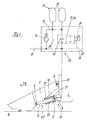
- Figure 1 shows schematically an agricultural machine 1, which on its in the direction of travel FR facing front end an agricultural, not shown Attachment device 2 pivots about an axis 3 pointing transversely to the direction of travel FR.
- Attachment device 2 pivots about an axis 3 pointing transversely to the direction of travel FR.
- the agricultural machine 1 at least one other transverse to the direction of travel FR pointing swivel axis 4 assigned to the frame.
- the at least one further pivot axis In the illustrated embodiment, 4 takes the piston 5 as a single-acting one Lift cylinder 6 executed lifting member 7, the piston rod 8 via a transverse to Axis 9 pointing in the direction of travel FR rotatable with the agricultural attachment 2 connected is.
- the at least one lifting cylinder 6 can be in the area its piston 5 are enclosed by a relief spring 10, the carrier vehicle side is in operative connection with a stop 11 and on the attachment side of the piston 5 encompassing and usually changing its position on the piston 5 stop 12th is limited.
- a supply line 13 connected via which the lifting cylinder 6 can be pressurized or depressurized can.
- the lifting cylinder 6 becomes an energy-transmitting medium via the supply line 12 supplied, the piston rod 8 is pushed out of the piston 5 and that with the Piston rod 8 pivotally connected agricultural attachment 2 pivoted about the arranged on the carrier vehicle 1 pivot axis 3 in the vertical direction upwards.
- the supply line 13 moves the front attachment 2 in a manner known per se, relieved of pressure by gravity the piston rod 8 back into the piston 5 and the attachment 2 now pivots counterclockwise around that arranged on the carrier vehicle 1 Swivel axis 3 back towards the floor 14. While the attachment 2 in the working position 1 is performed directly above the floor 14, it can in the Transport position of the at least one pressurized lifting cylinder 6 in any positions far from the ground are held. Depending on the unevenness of the floor 14 and the driving speed of the carrier vehicle 1, the attachment 2 performs pitching movements from that in the at least one lifting cylinder 6 for short-term pressure increases lead, among other things, as shock loads in the area of the fixed pivot axis 4 be introduced into the carrier vehicle 1.
- Control member 15 is in one 1 embodiment of a check valve 16 and a 2/2-way valve 17 formed, the check valve 16 and the 2/2-way valve 17 in parallel to each other and to which at least one lifting cylinder 6 are arranged.
- Control member 15 and the at least one lifting cylinder 6 via the at least one supply line 13 pressurized and relieved of pressure.
- inlet and outlet line 18 connected connections of the check valve 16 and the not shown 2/2-way valve 17 are in parallel with one another and with one of two via a line system 19 connected individual pressure accumulators 20 connected pressure accumulator unit 21. It is within the scope of the invention that the pressure accumulator unit 21 also has only a single pressure accumulator 20 or a plurality of individual pressure accumulators 20 can be formed.
- the check valve 16 connects the inlet and outlet line 18 to the line system 19 in such a way that the energy transfer medium of the inlet and outlet line 18 is the check valve 16 only in the direction of the line system 19 and thus in the direction of the pressure storage unit 21 and 2/2-way valve 17 can flow through.
- the 2/2-way valve 17 is designed so that it is in a first switch position (Fig. 1), the open position, the line system 19 with the inlet and outlet line 18 and the supply line 13 of the lifting cylinder 6 connects, the energy-transmitting medium in this switching position from the line system 19 and thus from the pressure storage unit 21 and the check valve 16 in the inlet and outlet line 18 and the supply line 13 of the lifting cylinder 6 flows.
- a second switching position the blocking position
- the 2/2-way valve 17 interrupts the connection between the line system 19 and the inlet and outlet line 18 and the supply line 13.
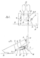
- this can be implemented as a 2/2-way valve 17 executed switching valve 26 can also be designed as a pressure relief valve 27, the Pressure relief valve 27, as shown in Figure 2, also in the open position or in Lock position can be operated to achieve the effects already described. moreover can be assigned to the pressure relief valve 27, a throttle 28, so that the high Pressure and high speed via the check valve 16 in the pressure storage unit 21 discharged oil with lower pressure and delayed, ie damped, the at least one Lift cylinder 6 is closed again.
- the pressure relief valve 27 can also via control lines 29, 30 with the line system 19 of the pressure storage unit 21 and the Supply line 13 and the pressure chamber 33 of the at least one lifting cylinder 6 connected be, so that also a pressure difference dependent opening or closing of the Pressure relief valve 27 can be achieved with the effect that the pressure storage unit 21 is not overloaded and the check valve 16 always against that in the line system 19 of the pressure storage unit 21 applied system pressure for reducing pressure peaks can open.
- the respective switching valve 17, 26, 27 can also be designed as a proportional valve 31 his.
- the lifting device 32 according to the invention has a May have a plurality of lifting members 7, all lifting members 7 at least one according to the invention Relief device 23 have to achieve the effects described.
- the lifting element 7 designed as a single-acting lifting cylinder 6 can also be operated by one or more double-acting, known per se and therefore not shown in detail Lift cylinders are formed.
Landscapes
- Engineering & Computer Science (AREA)
- Life Sciences & Earth Sciences (AREA)
- Mechanical Engineering (AREA)
- Soil Sciences (AREA)
- Environmental Sciences (AREA)
- Physics & Mathematics (AREA)
- Fluid Mechanics (AREA)
- General Engineering & Computer Science (AREA)
- Fluid-Pressure Circuits (AREA)
- Lifting Devices For Agricultural Implements (AREA)
Abstract
Description
- Figur 1
- eine erfindungsgemäße Entlastungsvorrichtung für eine Hubeinrichtung mit 2/2-Wegeventil
- Figur 2
- eine erfindungsgemäße Entlastungsvorrichtung für eine Hubeinrichtung mit Druckbegrenzungsventil
- 1
- landwirtschaftliche Arbeitsmaschine
- 2
- Vorsatzgerät
- 3
- Schwenkachse
- 4
- Schwenkachse
- 5
- Kolben
- 6
- Hubzylinder
- 7
- Huborgan
- 8
- Kolbenstange
- 9
- Schwenkachse
- 10
- Entlastungsfeder
- 11
- Anschlag
- 12
- Anschlag
- 13
- Versorgungsleitung
- 14
- Boden
- 15
- Steuerglied
- 16
- Rückschlagventil
- 17
- 2/2-Wegeventil
- 18
- Zu- und Ablaufleitung
- 19
- Leitungssystem
- 20
- Einzeldruckspeicher
- 21
- Druckspeichereinheit
- 22
- Drosselquerschnitt
- 23
- Entlastungsvorrichtung
- 24
- Steuerleitung
- 25
- Steuerleitung
- 26
- Schaltventil
- 27
- Druckbegrenzungsventil
- 28
- Drosselquerschnitt
- 29
- Steuerleitung
- 30
- Steuerleitung
- 31
- Proportionalventil
- 32
- Hubeinrichtung
- 33
- Druckraum
- FR
- Fahrtrichtung
Claims (13)
- Entlastungsvorrichtung für eine Hubeinrichtung mit zumindest einem fluidbetätigtem Huborgan, dessen wenigstens eine fluidführende Leitung über zumindest ein Steuerglied das fluidbetätigte Huborgan mit einer Druckspeichereinheit verbindet,
dadurch gekennzeichnet, dass das zumindest eine Steuerglied (15) von wenigstens einem in Durchlassrichtung das fluidbetätigte Huborgan (6, 7) mit der Druckspeichereinheit (21) verbindenden Rückschlagventil (16) und einem zu diesem Rückschlagventil (16) parallel geschalteten in Durchlassrichtung die Druckspeichereinheit (21) mit dem fluidbetätigten Huborgan (6, 7) verbindenden Schaltventil (26, 17, 27) gebildet wird. - Entlastungsvorrichtung nach Anspruch 1,
dadurch gekennzeichnet, dass der Durchfluss des energieübertragenden Mediums vom Rückschlagventil (16) zur Druckspeichereinheit (21) nahezu drosselfrei erfolgt. - Entlastungsvorrichtung für eine Hubeinrichtung nach einem oder mehreren der vorhergehenden Ansprüche,
dadurch gekennzeichnet, dass der Durchfluss des energieübertragenden Mediums von der Druckspeichereinheit (21) zu dem fluidbetätigtem Huborgan (6, 7) über einen Drosselquerschnitt (22, 28) oder nahezu drosselfrei erfolgt. - Entlastungsvorrichtung für eine Hubeinrichtung nach einem oder mehreren der vorhergehenden Ansprüche,
dadurch gekennzeichnet, dass das Schaltventil (26) als schaltbares 2/2-Wegeventil (17) ausgeführt ist, wobei das 2/2 Wegeventil (17) in Durchlassstellung den wenigstens einen Druckspeicher (20) mit dem wenigstens einen fluidbetätigten Huborgan (6, 7) verbindet und in Sperrstellung unterbricht. - Entlastungsvorrichtung für eine Hubeinrichtung nach Anspruch 4,
dadurch gekennzeichnet, dass das 2/2-Wegeventil (17) als vorgesteuertes 2/2 Wegeventil (17) ausgeführt ist, wobei die Vorsteuerfunktion durch die Druckdifferenz zwischen dem wenigstens einen Druckspeicher (20) und dem Druckraum (33) des wenigstens einen Huborgans (6, 7) bestimmt wird. - Entlastungsvorrichtung für eine Hubeinrichtung nach einem oder mehreren der vorhergehenden Ansprüche,
dadurch gekennzeichnet, dass die Durchlassstellung des 2/2-Wegeventils (17) als Drosselquerschnitt (22) ausgebildet ist. - Entlastungsvorrichtung für eine Hubeinrichtung nach einem oder mehreren der vorhergehenden Ansprüche,
dadurch gekennzeichnet, dass das Schaltventil (26) als Druckbegrenzungsventil (27) ausgeführt ist, wobei das Druckbegrenzungsventil (27) in Nullstellung den wenigstens einen Druckspeicher (20) mit dem Druckraum (33) des fluidbetätigten Huborgans (6, 7) verbindet und in Schaltstellung zumindest solange unterbricht, bis im Leitungssystem (19) der Druckspeichereinheit (21) ein am Druckbegrenzungsventil (27) voreinstellbarer Grenzdruck erreicht wird. - Entlastungsvorrichtung für eine Hubeinrichtung nach Anspruch 7,
dadurch gekennzeichnet, dass das Druckbegrenzungsventil (27) als gesteuertes Druckbegrenzungsventil (27) ausgeführt ist, wobei die Steuerfunktion durch die Druckdifferenz zwischen dem wenigstens einen Druckspeicher (10) und dem Druckraum (33) des wenigstens einen Huborgans (6, 7) bestimmt wird. - Entlastungsvorrichtung für eine Hubeinrichtung nach einem oder mehreren der vorhergehenden Ansprüche,
dadurch gekennzeichnet, dass das Schaltventil (17, 26, 27) als Proportionalventil (31) ausgebildet ist. - Entlastungsvorrichtung für eine Hubeinrichtung nach einem oder mehreren der vorhergehenden Ansprüche,
dadurch gekennzeichnet, dass die Druckspeichereinheit (21) über eine Vielzahl parallel geschalteter Einzeldruckspeicher (20) verfügt. - Entlastungsvorrichtung für eine Hubeinrichtung nach einem oder mehreren der vorhergehenden Ansprüche,
dadurch gekennzeichnet, dass das fluidbetätigte Huborgan (6, 7) als hydraulischer Hubzylinder (6) ausgeführt ist. - Entlastungsvorrichtung für eine Hubeinrichtung nach einem oder mehreren der vorhergehenden Ansprüche,
dadurch gekennzeichnet, dass das wenigstens eine fluidbetätigte Huborgan (6, 7) einenends schwenkbeweglich mit einem als landwirtschaftliche Arbeitsmaschine (1) ausgeführten Trägerfahrzeug verbunden ist und anderenends schwenkbeweglich mit wenigstens einem höhenverstellbaren Arbeitsorgan (2) in Wirkverbindung steht. - Entlastungsvorrichtung für eine Hubeinrichtung nach Anspruch 12,
dadurch gekennzeichnet, dass das Arbeitsorgan (2) ein Vorsatzgerät zur Ernte und Aufnahme landwirtschaftlicher Erntegüter ist.
Applications Claiming Priority (2)
| Application Number | Priority Date | Filing Date | Title |
|---|---|---|---|
| DE2001127486 DE10127486A1 (de) | 2001-06-07 | 2001-06-07 | Entlastungsvorrichtung für eine Hubeinrichtung |
| DE10127486 | 2001-06-07 |
Publications (1)
| Publication Number | Publication Date |
|---|---|
| EP1264989A1 true EP1264989A1 (de) | 2002-12-11 |
Family
ID=7687390
Family Applications (1)
| Application Number | Title | Priority Date | Filing Date |
|---|---|---|---|
| EP02011317A Ceased EP1264989A1 (de) | 2001-06-07 | 2002-05-23 | Entlastungsvorrichtung für eine Hubeinrichtung |
Country Status (2)
| Country | Link |
|---|---|
| EP (1) | EP1264989A1 (de) |
| DE (1) | DE10127486A1 (de) |
Cited By (14)
| Publication number | Priority date | Publication date | Assignee | Title |
|---|---|---|---|---|
| WO2004071929A1 (en) * | 2003-02-14 | 2004-08-26 | Hultdin System Ab | Damping device |
| EP1589218A1 (de) * | 2004-04-20 | 2005-10-26 | Robert Bosch Gmbh | Schwingungsdämpfer für ein Hydrauliksystem |
| WO2006005497A1 (de) * | 2004-07-13 | 2006-01-19 | Bosch Rexroth Ag | Hydraulische steueranordnung |
| WO2012038134A1 (de) * | 2010-09-20 | 2012-03-29 | Zf Friedrichshafen Ag | Speicheranordnung für eine hydraulikversorgung eines fahrzeuggetriebes |
| WO2012038133A1 (de) * | 2010-09-20 | 2012-03-29 | Zf Friedrichshafen Ag | Speicheranordnung für eine hydraulikversorgung eines fahrzeuggetriebes |
| DE102006038801B4 (de) * | 2006-08-18 | 2014-02-06 | Amazonen-Werke H. Dreyer Gmbh & Co. Kg | Landwirtschaftliche Maschine mit hydraulischer Betätigungseinrichtung |
| CN111819991A (zh) * | 2019-04-23 | 2020-10-27 | 迪尔公司 | 农业收割机上的用于割台找平的受控浮体 |
| US11219162B2 (en) | 2019-04-23 | 2022-01-11 | Deere & Company | Controlled header lowering on an agricultural harvester |
| US11224164B2 (en) | 2019-04-23 | 2022-01-18 | Deere & Company | Damped float response on an agricultural harvester |
| US11272659B2 (en) * | 2019-03-27 | 2022-03-15 | Deere & Company | Controlled or tuned float on an agricultural harvester to modify float response |
| CN114590749A (zh) * | 2022-02-25 | 2022-06-07 | 安徽合力股份有限公司 | 一种带冲击吸收的叉车全自由门架液压系统 |
| US11490567B2 (en) | 2019-12-16 | 2022-11-08 | Cnh Industrial America Llc | System for unloading particulate material from an agricultural machine |
| US20230276730A1 (en) * | 2020-07-24 | 2023-09-07 | CNH Industrial Brasil Ltda. | Harvesting system based on a platform for agricultural harvesters, and platform for agricultural harvesters |
| FI131708B1 (sv) * | 2016-09-12 | 2025-10-06 | Hultdin System Ab | Dämpningsanordning |
Families Citing this family (2)
| Publication number | Priority date | Publication date | Assignee | Title |
|---|---|---|---|---|
| DE102004028396A1 (de) * | 2004-06-14 | 2005-12-29 | Claas Selbstfahrende Erntemaschinen Gmbh | Bodenkopiervorrichtung |
| CN112293046B (zh) * | 2019-07-26 | 2024-07-02 | 科乐收印度私人有限公司 | 具有高度可调的加工工具的农业机械 |
Citations (5)
| Publication number | Priority date | Publication date | Assignee | Title |
|---|---|---|---|---|
| DE2856583A1 (de) | 1978-12-22 | 1980-06-26 | Alfred Dipl Ing Ulrich | Fahrzeug mit angekoppelten und/oder festangebauten heck- und/oder frontanbaugeraeten und/oder seitlich angebaute geraete |
| EP0388641A2 (de) * | 1989-03-21 | 1990-09-26 | Hanomag Aktiengesellschaft | Hydraulikanlage für Baumaschinen, insbesondere für Radlader, Schlepper u. dgl. |
| DE4216780A1 (de) * | 1992-05-21 | 1993-12-02 | Orenstein & Koppel Ag | Vorrichtung zum Heben und Senken eines mit einer schwenkbaren Schaufel versehenen Auslegers einer fahrbaren Baumaschine |
| DE4416194A1 (de) * | 1994-05-06 | 1995-11-09 | Rexroth Mannesmann Gmbh | Regelsystem für einen hydraulisch betätigten Verbraucher eines Nutzfahrzeugs |
| DE19622762A1 (de) | 1996-06-07 | 1997-12-11 | Rexroth Mannesmann Gmbh | Nutzfahrzeug, insbesondere für die Landwirtschaft |
Family Cites Families (2)
| Publication number | Priority date | Publication date | Assignee | Title |
|---|---|---|---|---|
| US3807678A (en) * | 1972-09-19 | 1974-04-30 | Lord Corp | System for controlling the transmission of energy between spaced members |
| DE2710440C2 (de) * | 1977-03-10 | 1987-04-16 | Baas Technik GmbH, 2000 Wedel | Vorrichtung zur aktiven Schwingungsdämpfung |
-
2001
- 2001-06-07 DE DE2001127486 patent/DE10127486A1/de not_active Withdrawn
-
2002
- 2002-05-23 EP EP02011317A patent/EP1264989A1/de not_active Ceased
Patent Citations (5)
| Publication number | Priority date | Publication date | Assignee | Title |
|---|---|---|---|---|
| DE2856583A1 (de) | 1978-12-22 | 1980-06-26 | Alfred Dipl Ing Ulrich | Fahrzeug mit angekoppelten und/oder festangebauten heck- und/oder frontanbaugeraeten und/oder seitlich angebaute geraete |
| EP0388641A2 (de) * | 1989-03-21 | 1990-09-26 | Hanomag Aktiengesellschaft | Hydraulikanlage für Baumaschinen, insbesondere für Radlader, Schlepper u. dgl. |
| DE4216780A1 (de) * | 1992-05-21 | 1993-12-02 | Orenstein & Koppel Ag | Vorrichtung zum Heben und Senken eines mit einer schwenkbaren Schaufel versehenen Auslegers einer fahrbaren Baumaschine |
| DE4416194A1 (de) * | 1994-05-06 | 1995-11-09 | Rexroth Mannesmann Gmbh | Regelsystem für einen hydraulisch betätigten Verbraucher eines Nutzfahrzeugs |
| DE19622762A1 (de) | 1996-06-07 | 1997-12-11 | Rexroth Mannesmann Gmbh | Nutzfahrzeug, insbesondere für die Landwirtschaft |
Cited By (20)
| Publication number | Priority date | Publication date | Assignee | Title |
|---|---|---|---|---|
| WO2004071929A1 (en) * | 2003-02-14 | 2004-08-26 | Hultdin System Ab | Damping device |
| EP1589218A1 (de) * | 2004-04-20 | 2005-10-26 | Robert Bosch Gmbh | Schwingungsdämpfer für ein Hydrauliksystem |
| WO2006005497A1 (de) * | 2004-07-13 | 2006-01-19 | Bosch Rexroth Ag | Hydraulische steueranordnung |
| US7637103B2 (en) | 2004-07-13 | 2009-12-29 | Bosch Rexroth Ag | Hydraulic control arrangement |
| CN101001996B (zh) * | 2004-07-13 | 2010-06-23 | 博世力士乐股份公司 | 液压控制装置 |
| KR101217755B1 (ko) * | 2004-07-13 | 2013-01-02 | 보쉬 렉스로트 아게 | 유압 제어 장치 |
| DE102006038801B4 (de) * | 2006-08-18 | 2014-02-06 | Amazonen-Werke H. Dreyer Gmbh & Co. Kg | Landwirtschaftliche Maschine mit hydraulischer Betätigungseinrichtung |
| WO2012038134A1 (de) * | 2010-09-20 | 2012-03-29 | Zf Friedrichshafen Ag | Speicheranordnung für eine hydraulikversorgung eines fahrzeuggetriebes |
| WO2012038133A1 (de) * | 2010-09-20 | 2012-03-29 | Zf Friedrichshafen Ag | Speicheranordnung für eine hydraulikversorgung eines fahrzeuggetriebes |
| FI131708B1 (sv) * | 2016-09-12 | 2025-10-06 | Hultdin System Ab | Dämpningsanordning |
| US11272659B2 (en) * | 2019-03-27 | 2022-03-15 | Deere & Company | Controlled or tuned float on an agricultural harvester to modify float response |
| US11191212B2 (en) | 2019-04-23 | 2021-12-07 | Deere & Company | Controlled float on an agricultural harvester for header leveling |
| US11224164B2 (en) | 2019-04-23 | 2022-01-18 | Deere & Company | Damped float response on an agricultural harvester |
| US11219162B2 (en) | 2019-04-23 | 2022-01-11 | Deere & Company | Controlled header lowering on an agricultural harvester |
| CN111819991B (zh) * | 2019-04-23 | 2023-05-09 | 迪尔公司 | 农业收割机上的用于割台找平的受控浮体 |
| US12018705B2 (en) | 2019-04-23 | 2024-06-25 | Deere & Company | Controlled float on an agricultural harvester for header leveling |
| CN111819991A (zh) * | 2019-04-23 | 2020-10-27 | 迪尔公司 | 农业收割机上的用于割台找平的受控浮体 |
| US11490567B2 (en) | 2019-12-16 | 2022-11-08 | Cnh Industrial America Llc | System for unloading particulate material from an agricultural machine |
| US20230276730A1 (en) * | 2020-07-24 | 2023-09-07 | CNH Industrial Brasil Ltda. | Harvesting system based on a platform for agricultural harvesters, and platform for agricultural harvesters |
| CN114590749A (zh) * | 2022-02-25 | 2022-06-07 | 安徽合力股份有限公司 | 一种带冲击吸收的叉车全自由门架液压系统 |
Also Published As
| Publication number | Publication date |
|---|---|
| DE10127486A1 (de) | 2002-12-12 |
Similar Documents
| Publication | Publication Date | Title |
|---|---|---|
| EP1915538B1 (de) | Schaltung zur ansteuerung eines doppeltwirkenden hydraulischen antriebszylinders | |
| EP1264989A1 (de) | Entlastungsvorrichtung für eine Hubeinrichtung | |
| EP1766146B1 (de) | Hubwerksventilanordnung | |
| DE102007040877A1 (de) | Hubwerk und Verfahren zum Ansteuern eines Hubwerkes | |
| DE10307346A1 (de) | Ventilanordnung | |
| EP0789816B1 (de) | Energierückgewinnungsvorrichtung | |
| EP1038070A1 (de) | Hydraulische steueranordnung für eine mobile arbeitsmaschine, insbesondere für einen radlader, zur dämpfung von nickschwingungen | |
| DE602005003696T2 (de) | Hydraulikzylinder zur Verwendung in einem hydraulischen Werkzeug | |
| DE102005038333A1 (de) | Hydraulische Anordnung | |
| DE202004017743U1 (de) | Fahrsteuerschaltung für eine Arbeitsmaschine | |
| DE102012208307A1 (de) | Dämpfungsvorrichtung | |
| EP1027821A2 (de) | Hydraulische Stelleinrichtung | |
| EP1721518B1 (de) | Einzugsorgansteuerung für landwirtschaftliche Arbeitsmaschine | |
| DE1951833B2 (de) | Hydraulische anlage an fahrbaren arbeitsmaschinen zur hoehenverstellung eines anbaugeraets | |
| DE102018210471B3 (de) | Hubwerksfederung und Hubwerk | |
| EP0877863A1 (de) | Hydraulische einrichtung zur steuerung des druckmittelflusses | |
| EP2016818B1 (de) | Hubwerk und Verfahren zum Ansteuern eines derartigen Hubwerks | |
| DE19548943B4 (de) | Ventilanordnung | |
| AT408475B (de) | Anordnung zur hydraulischen betätigung eines beweglichen bauteils an einem fahrzeug | |
| DE102010026453A1 (de) | Hubwerk | |
| DE4135013C2 (de) | Hydraulisches Antriebssystem | |
| EP4275465B1 (de) | Hydraulische verstellvorrichtung | |
| EP3002462B1 (de) | Hydraulisches steuersystem | |
| EP1590572B1 (de) | Federungsvorrichtung | |
| DE102006004423A1 (de) | Ventilanordnung zur Ansteuerung eines Hubwerkes oder Anbaugerätes |
Legal Events
| Date | Code | Title | Description |
|---|---|---|---|
| PUAI | Public reference made under article 153(3) epc to a published international application that has entered the european phase |
Free format text: ORIGINAL CODE: 0009012 |
|
| AK | Designated contracting states |
Kind code of ref document: A1 Designated state(s): AT BE CH CY DE DK ES FI FR GB GR IE IT LI LU MC NL PT SE TR |
|
| AX | Request for extension of the european patent |
Free format text: AL;LT;LV;MK;RO;SI |
|
| 17P | Request for examination filed |
Effective date: 20030611 |
|
| AKX | Designation fees paid |
Designated state(s): AT BE CH CY DE DK ES FI FR GB GR IE IT LI LU MC NL PT SE TR |
|
| 17Q | First examination report despatched |
Effective date: 20030903 |
|
| APBN | Date of receipt of notice of appeal recorded |
Free format text: ORIGINAL CODE: EPIDOSNNOA2E |
|
| APBR | Date of receipt of statement of grounds of appeal recorded |
Free format text: ORIGINAL CODE: EPIDOSNNOA3E |
|
| APAF | Appeal reference modified |
Free format text: ORIGINAL CODE: EPIDOSCREFNE |
|
| APAF | Appeal reference modified |
Free format text: ORIGINAL CODE: EPIDOSCREFNE |
|
| APBT | Appeal procedure closed |
Free format text: ORIGINAL CODE: EPIDOSNNOA9E |
|
| STAA | Information on the status of an ep patent application or granted ep patent |
Free format text: STATUS: THE APPLICATION HAS BEEN REFUSED |
|
| 18R | Application refused |
Effective date: 20071019 |