EP1265026A2 - Dispositif d'éclairage pour véhicules et son procédé d'assemblage - Google Patents
Dispositif d'éclairage pour véhicules et son procédé d'assemblage Download PDFInfo
- Publication number
- EP1265026A2 EP1265026A2 EP02012572A EP02012572A EP1265026A2 EP 1265026 A2 EP1265026 A2 EP 1265026A2 EP 02012572 A EP02012572 A EP 02012572A EP 02012572 A EP02012572 A EP 02012572A EP 1265026 A2 EP1265026 A2 EP 1265026A2
- Authority
- EP
- European Patent Office
- Prior art keywords
- light source
- adapter
- rear wall
- housing
- connection
- Prior art date
- Legal status (The legal status is an assumption and is not a legal conclusion. Google has not performed a legal analysis and makes no representation as to the accuracy of the status listed.)
- Granted
Links
- 238000000034 method Methods 0.000 title claims abstract description 8
- 238000003780 insertion Methods 0.000 claims description 5
- 230000037431 insertion Effects 0.000 claims description 5
- 239000013067 intermediate product Substances 0.000 claims description 3
- 238000005452 bending Methods 0.000 description 2
- 230000001154 acute effect Effects 0.000 description 1
- 230000015572 biosynthetic process Effects 0.000 description 1
- 238000002788 crimping Methods 0.000 description 1
- 230000000694 effects Effects 0.000 description 1
- 239000000463 material Substances 0.000 description 1
Images


Classifications
-
- F—MECHANICAL ENGINEERING; LIGHTING; HEATING; WEAPONS; BLASTING
- F21—LIGHTING
- F21S—NON-PORTABLE LIGHTING DEVICES; SYSTEMS THEREOF; VEHICLE LIGHTING DEVICES SPECIALLY ADAPTED FOR VEHICLE EXTERIORS
- F21S43/00—Signalling devices specially adapted for vehicle exteriors, e.g. brake lamps, direction indicator lights or reversing lights
- F21S43/10—Signalling devices specially adapted for vehicle exteriors, e.g. brake lamps, direction indicator lights or reversing lights characterised by the light source
- F21S43/19—Attachment of light sources or lamp holders
- F21S43/195—Details of lamp holders, terminals or connectors
-
- F—MECHANICAL ENGINEERING; LIGHTING; HEATING; WEAPONS; BLASTING
- F21—LIGHTING
- F21S—NON-PORTABLE LIGHTING DEVICES; SYSTEMS THEREOF; VEHICLE LIGHTING DEVICES SPECIALLY ADAPTED FOR VEHICLE EXTERIORS
- F21S43/00—Signalling devices specially adapted for vehicle exteriors, e.g. brake lamps, direction indicator lights or reversing lights
- F21S43/10—Signalling devices specially adapted for vehicle exteriors, e.g. brake lamps, direction indicator lights or reversing lights characterised by the light source
- F21S43/19—Attachment of light sources or lamp holders
Definitions
- the invention relates to a device for lighting vehicles a light source with a light source carrier in which the light source can be used is and has contact elements for electrical connection with the Light source and for electrical connection with one with an electrical Voltage source related electrical line, with a Housing which has an opening on a rear wall thereof for insertion and releasably attaching the light source support.
- the invention further relates to a method for mounting a light source according to the preamble of claim 11.
- DE 44 18 399 A1 describes a device for illuminating vehicles known that a light source support with a receptacle for a light source has, wherein the light source carrier has electrical contact elements for electrical connection with the light source on the one hand and for electrical connection with electrical arranged on a rear wall of a housing Connections on the other hand, from which electrical lines to a remote dissipate the arranged electrical voltage source.
- the electrical lines run inside the housing from an electrical connection point in the Area of an opening in the rear wall into which the light source carrier can be inserted is to a central arranged in a further opening of the rear wall Plug part from which the arriving from the individual light sources Cables combined to the remote electrical voltage source to get redirected.
- a disadvantage of the known device is that the effort for the attachment of electrical contact elements on the rear wall of the housing relative is complex. In addition to providing a central plug part in an opening the rear wall are attached to a contact point in the area of the Light source carrier contacting measures necessary. The assembly effort is relatively large.
- the object of the present invention is therefore a device for lighting of vehicles and to specify a method for mounting a light source, so that on the one hand a simple and secure contact connection of the Light source is achieved in the area of the rear wall and that to the other the assembly effort is reduced.
- the invention is in connection with the Preamble of claim 1 characterized in that the light source carrier releasably connected to the rear wall of the housing via an adapter is, the adapter fasteners for mechanical connection with the light source carrier and / or the rear wall of the housing and wherein the adapter has contact elements for electrical connection with contact elements of the light source carrier on the one hand and connection ends the electrical line on the other hand.
- the particular advantage of the device according to the invention is that by providing an adapter on the one hand a mechanical connection a rear wall of the housing is created.
- the other is the adapter formed such that an electrical connection between the light source or the light source carrier and the remote voltage source leading electrical lines bypassing contacting measures can be done on the rear wall of the housing. In the electrical contacting thus decouples the rear wall of the Housing, so that the mounting of the light source on the rear wall of the housing is simplified.
- the adapter provides a mechanical connector between the light source carrier and the housing.
- the fact that the Adapters already contact elements for electrical connection with connection ends of the electrical lines, these connection ends can already before mounting the light source carrier electrically with the contact elements of the adapter, the adapter being an intermediate product for assembly can be provided. Together with the light source carrier the adapter is inserted into the opening of the rear wall and mechanically with the same connected.
- the adapter has fastening means on, by means of which the adapter is detachable with the light source carrier on the one hand and the rear wall of the housing is connected on the other hand.
- This can be advantageous the light source is removed only by removing the light source carrier without changing the position of the electrical cables would have to be.
- the adapter can basically be fixed in the opening of the The rear wall remains and thus serves as an electrical and mechanical connection element for the light source carrier.
- the fastening means of the adapter or the light source carrier designed such that the holding force between the adapter and the rear wall is greater than the holding force between the adapter and the light source carrier.
- the adapter is ring-shaped and has at least two barbed latches, which after insertion of the adapter into the opening behind the rear wall of the housing.
- a secure positive connection between the Adapters and the back panel ensures that only in exceptional cases Bending the locking lugs in the transverse direction to the longitudinal axis of the light source carrier can be solved.
- the adapter is advantageously mounted exclusively by a longitudinal movement of the same together with the light source carrier, until the detents arranged preferably opposite one another reach behind the rear wall of the housing with their barbs.
- the adapter points to one of the rear walls of the housing opposite rear side a groove for receiving connection ends the electrical cables (connection ends of the receiving groove), in which the connection ends of the electrical line with the contact elements of the adapter are electrically connected.
- the contacting of the connection ends the electrical line is thus carried out in a defined and preferably area of the adapter covered to the outside by an axial collar.
- the electrical contact elements are accessible from the outside avoided, so that there is no undesirable short circuit when changing the light source with negative effects on the on-board electronics.
- the light source carrier is hollow cylindrical formed and has guide elements by means of which the light source carrier fits snugly into the adapter.
- the Light source carrier resilient locking lugs on the ring wall of the adapter reach behind and thus a mechanical connection with the adapter produce.
- the fact that the locking lugs are opposite to the mounting direction have tapered inclined surface can counteract a force when attacked the direction of assembly this attack power can be redirected with formation a transverse component that causes the detent bending of the locking lugs.
- the connection between the light source carrier and the adapter be solved.
- By gripping a handle element of the light source carrier and exerting a corresponding force can be user-friendly the light source carrier be removed for a change of light source.
- the particular advantage of the method according to the invention is that the adapter together with the electrical lines contacted to the same can be provided as an intermediate product, so that for assembly the light source only the adapter together with the light source carrier in the opening of the rear wall of the housing needs to be inserted. This can preferably be done in a single step, so that the assembly effort can be significantly reduced.
- both the light source carrier with the adapter as well as the adapter with the rear wall of the housing Locking releasably connected the locking elements are designed such that the locking force holding the connection between the adapter and the Rear wall is greater than the locking force holding the connection between the Light source carrier and the adapter.
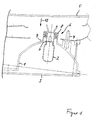
- FIG. 1 shows a housing 1 for such a lighting device, which in the area is designed in a pot shape by light sources 2.
- the housing 1 is on the outside completely through a preferably colored cover plate 3 covered.
- the housing 1 is mechanical by means of fastening elements 4 connected to a body part 5 of the vehicle.
- An opening 6 is provided in an apex region of the housing 1, into which the light source 2 is used.
- the light source 2 is in a light source carrier 7 stored, which engages in an annular adapter 8 and over the same is connected to a rear wall 9 of the housing 1.
- both the light source carrier 7 and also the adapter 8 fasteners such that on the one hand the light source carrier 7 with the adapter 8 and on the other hand the adapter 8 with the Rear wall 9 of the housing 1 is detachably connected.
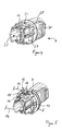
- the adapter 8 points opposite Sides each have a locking lug 10 with free ends arranged barbs 11 engage behind the rear wall 9 of the housing 1.
- the locking lugs 10 are relatively torsionally rigid and have an in Transversely extending recess 12, the width of which corresponds to the thickness of the rear wall 9 of the housing 1 corresponds. This is a safe mechanical one Ensures connection between the adapter 8 and the rear wall 9, unlocking the connection only by immediate attack a force at the end of the locking lug 10 can take place in the transverse direction.
- the adapter 8 not only serves as a mechanical connecting element between the light source support 7 and the rear wall 9 of the housing 1.
- the adapter 8 also serves as a contact ring for the electrical connection of the light source 2 to a remote voltage source.
- the Adapter 8 has a connection end receiving groove on opposite sides 13 for receiving connection ends of a leading to the voltage source electrical line 14 on.
- the receiving groove 13 is along a ring section of the adapter 8 on a side of the light source 2 facing away Adapters 8 arranged so that the connection ends as well as the electrical Lines 14 run outside the pot-shaped housing 1.
- the housing 1 is therefore advantageously free of electrical contacting means.
- connection ends of the electrical line 14 are by crimping in the Receiving groove 13 connected to electrical contact elements 15 of the adapter 8. So that the electrical contact between the connection ends of the electrical line 14 and the contact elements 15 protected from the outside is, the receiving groove 13 has an axial collar 16, which is the contact point covers and protects.
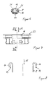
- the respectively the connection ends of the electrical Line 14 associated contact elements 15 of the adapter 8 are made made and extend an electrically conductive and bendable material from the contact point in the receiving groove 13 from an outside 17 of the adapter 8 with deflection in the direction of an assembly direction 18 by 180 ° on an inside 19 of the adapter 8, on which a further contact point is arranged.
- the contact elements 15 are each clamping attached to the adapter 8.
- contact elements 15 For electrical contacting of the light source carrier 7 with the respective the inside 19 of the adapter 8 arranged contact elements 15 has the Light source support 7 in the transverse direction contact springs 20, the opposite the outer edge forming a bulbous or convex shape form the light source carrier 7 in the area of the contact points.
- the Spring force of the contact springs 20 is designed such that mechanical Connection between the light source carrier 7 and the adapter 8 a predetermined Contacting force is exercised.
- the contact springs 20 are each via inwardly folded contact strips 21 to an internal contact point 22 out in which after inserting the light source 2 in a receptacle 23 of the light source carrier 7 an electrical connection to connections the light source 2 is made.
- the light source support 7 On opposite sides in the transverse direction to the same bendable locking lugs 24, which in the assembled state reach behind the inside 19 of the adapter 8.
- a tapering against the mounting direction 18 Inclined surface 26 provided that the light source support 7 is released from the frictional connection with the adapter 8.
- the inclined surface 26 is an acute angle to the longitudinal axis of the light source carrier 7 forms, is when attacking an unlocking force against Mounting direction 18 always before a shear force component, the radially inward is directed and causes the locking lugs 24 to pivot inwards. On in this way the light source carrier 7 can be unlocked by the adapter 8 and be pushed out.
- the light source carrier 7 has guide elements 27, so that with one exception the locking lugs 24 fit precisely through the annular adapter 8 with the Recording 23 can be inserted until a flange 28 of the light source carrier 7 strikes an annular surface 29 of the adapter 8. With the stop of the Flange 28 on the annular surface 29 of the adapter 8 is engaged Lugs 24 so that a secure mechanical connection between the Light source support 7 and the adapter 8 is made. Preferably done before introduction the light source carrier 7 in the adapter 8 already inserting the Light source 2 in the receptacle 23 of the light source carrier 7.
- the light source carrier 7 on the rear wall 9 of the housing 1 becomes the light source carrier 7 on a rear handle element 30 by a suitable handling device detected - this can also be done manually - with the light source 2 inserted through the opening of the adapter 8 until it locks into place he follows. Then the light source carrier 7 and the adapter 8 formed unit in the mounting direction 18 in the opening of the rear wall 9 of the Housing 1 used until the adapter 8 is locked by means of the locking lugs 10 with the rear wall 9 of the housing 1. The assembly is therefore done easily by moving the assembly in a longitudinal direction.
- the adapter 8 could also first enter the opening in the rear wall 9 be used, after which the light source carrier 7 in the opening of the adapter 8th is used.
- the adapter 8 has on the inside 19th opposing notches 31, which serve as protection against confusion.
- the light source 2 can be designed as an incandescent lamp or light-emitting diode.
Landscapes
- Engineering & Computer Science (AREA)
- General Engineering & Computer Science (AREA)
- Arrangement Of Elements, Cooling, Sealing, Or The Like Of Lighting Devices (AREA)
- Arrangements Of Lighting Devices For Vehicle Interiors, Mounting And Supporting Thereof, Circuits Therefore (AREA)
Applications Claiming Priority (2)
| Application Number | Priority Date | Filing Date | Title |
|---|---|---|---|
| DE10127965A DE10127965A1 (de) | 2001-06-08 | 2001-06-08 | Vorrichtung zur Beleuchtung von Fahrzeugen und Montageverfahren |
| DE10127965 | 2001-06-08 |
Publications (3)
| Publication Number | Publication Date |
|---|---|
| EP1265026A2 true EP1265026A2 (fr) | 2002-12-11 |
| EP1265026A3 EP1265026A3 (fr) | 2005-09-14 |
| EP1265026B1 EP1265026B1 (fr) | 2007-09-19 |
Family
ID=7687704
Family Applications (1)
| Application Number | Title | Priority Date | Filing Date |
|---|---|---|---|
| EP02012572A Expired - Lifetime EP1265026B1 (fr) | 2001-06-08 | 2002-06-06 | Dispositif d'éclairage pour véhicules et son procédé d'assemblage |
Country Status (2)
| Country | Link |
|---|---|
| EP (1) | EP1265026B1 (fr) |
| DE (2) | DE10127965A1 (fr) |
Cited By (1)
| Publication number | Priority date | Publication date | Assignee | Title |
|---|---|---|---|---|
| EP1479503A1 (fr) * | 2003-05-21 | 2004-11-24 | Hella KGaA Hueck & Co. | Pièce moulée par injection pour une lampe de véhicule et procédé de fabrication |
Citations (1)
| Publication number | Priority date | Publication date | Assignee | Title |
|---|---|---|---|---|
| DE4418399A1 (de) | 1994-05-26 | 1995-11-30 | Bosch Gmbh Robert | Beleuchtungseinrichtung für Fahrzeuge |
Family Cites Families (6)
| Publication number | Priority date | Publication date | Assignee | Title |
|---|---|---|---|---|
| DE3715532C2 (de) * | 1987-05-09 | 1995-08-31 | Bosch Gmbh Robert | Leuchte für Kraftfahrzeuge, insbesondere vordere Park- und/oder Begrenzungsleuchte für Personenkraftfahrzeuge |
| JPH0617003U (ja) * | 1992-06-12 | 1994-03-04 | スタンレー電気株式会社 | 車両用前照灯の電球取付部 |
| DE19822895A1 (de) * | 1997-08-22 | 1999-02-25 | Bosch Gmbh Robert | Beleuchtungseinrichtung für Fahrzeuge |
| FR2776050B1 (fr) * | 1998-03-11 | 2000-06-16 | Valeo Vision | Projecteur notamment pour vehicule automobile comportant un porte-lampe a connexion simplifiee |
| DE19927142C1 (de) * | 1999-06-15 | 2000-12-07 | Sidler Gmbh & Co | Reflektorleuchte |
| JP2001155514A (ja) * | 1999-11-30 | 2001-06-08 | Yazaki Corp | リアコンビネーションランプ |
-
2001
- 2001-06-08 DE DE10127965A patent/DE10127965A1/de not_active Withdrawn
-
2002
- 2002-06-06 EP EP02012572A patent/EP1265026B1/fr not_active Expired - Lifetime
- 2002-06-06 DE DE50210910T patent/DE50210910D1/de not_active Expired - Lifetime
Patent Citations (1)
| Publication number | Priority date | Publication date | Assignee | Title |
|---|---|---|---|---|
| DE4418399A1 (de) | 1994-05-26 | 1995-11-30 | Bosch Gmbh Robert | Beleuchtungseinrichtung für Fahrzeuge |
Cited By (1)
| Publication number | Priority date | Publication date | Assignee | Title |
|---|---|---|---|---|
| EP1479503A1 (fr) * | 2003-05-21 | 2004-11-24 | Hella KGaA Hueck & Co. | Pièce moulée par injection pour une lampe de véhicule et procédé de fabrication |
Also Published As
| Publication number | Publication date |
|---|---|
| EP1265026A3 (fr) | 2005-09-14 |
| DE50210910D1 (de) | 2007-10-31 |
| DE10127965A1 (de) | 2002-12-12 |
| EP1265026B1 (fr) | 2007-09-19 |
Similar Documents
| Publication | Publication Date | Title |
|---|---|---|
| EP1851830B1 (fr) | Systeme de liaison, notamment systeme de connexion electrique | |
| DE3629634C2 (fr) | ||
| DE4433704A1 (de) | Steckbuchse | |
| DE2943503A1 (de) | Kombination eines adapters und einer stromentnahmeschiene | |
| EP1155475B1 (fr) | Connecteur electrique a fiches | |
| DE102013104704B4 (de) | Kraftfahrzeugzündeinheit | |
| EP1671399B1 (fr) | Raccordement d'element de blindage | |
| EP0319633B1 (fr) | Connecteur cinch | |
| DE4410072A1 (de) | Koaxialkabel-Steckverbinderanordnung | |
| DE2323612A1 (de) | Elektrisches verbindungsglied | |
| DE3433822A1 (de) | Verbindungsvorrichtung | |
| DE102012110791A1 (de) | Kraftfahrzeugaktuator | |
| EP1265026A2 (fr) | Dispositif d'éclairage pour véhicules et son procédé d'assemblage | |
| DE3147654A1 (de) | "waermeschutzschild oder -abschirmung fuer elektrische maschine" | |
| DE19525801C2 (de) | Vorrichtung zum elektrisch leitenden Verbinden von zwei elektrischen Leitungen | |
| EP0129754A1 (fr) | Outil électrique à main avec un boîtier divisible | |
| DE69602143T2 (de) | Gehäuse für ein elektrisches Bauteil | |
| DE3001990A1 (de) | Lampenhalter | |
| EP1560303A2 (fr) | Elément de contact pour la connexion électrique des feux principaux d' éclairage à un socle | |
| DE10146430A1 (de) | Steckverbinder für Airbagsysteme | |
| DE4430161A1 (de) | Handwerkzeugmaschine | |
| DE202017102166U1 (de) | Vorrichtung zum positionsgerechten Befestigen einer Antennenanordnung | |
| DE2252145A1 (de) | Lampenhalter | |
| EP0705731A2 (fr) | Feu de véhicule en particulier pour plaque d'immatriculation | |
| DE102007025605A1 (de) | Fahrzeugantenne |
Legal Events
| Date | Code | Title | Description |
|---|---|---|---|
| PUAI | Public reference made under article 153(3) epc to a published international application that has entered the european phase |
Free format text: ORIGINAL CODE: 0009012 |
|
| AK | Designated contracting states |
Kind code of ref document: A2 Designated state(s): AT BE CH CY DE DK ES FI FR GB GR IE IT LI LU MC NL PT SE TR |
|
| AX | Request for extension of the european patent |
Free format text: AL;LT;LV;MK;RO;SI |
|
| RAP1 | Party data changed (applicant data changed or rights of an application transferred) |
Owner name: HELLA KGAA HUECK & CO. |
|
| PUAL | Search report despatched |
Free format text: ORIGINAL CODE: 0009013 |
|
| AK | Designated contracting states |
Kind code of ref document: A3 Designated state(s): AT BE CH CY DE DK ES FI FR GB GR IE IT LI LU MC NL PT SE TR |
|
| AX | Request for extension of the european patent |
Extension state: AL LT LV MK RO SI |
|
| 17P | Request for examination filed |
Effective date: 20060309 |
|
| AKX | Designation fees paid |
Designated state(s): DE ES FR GB IT |
|
| GRAP | Despatch of communication of intention to grant a patent |
Free format text: ORIGINAL CODE: EPIDOSNIGR1 |
|
| RIC1 | Information provided on ipc code assigned before grant |
Ipc: F21W 101/14 20060101ALI20070328BHEP Ipc: F21V 19/00 20060101AFI20070328BHEP |
|
| GRAS | Grant fee paid |
Free format text: ORIGINAL CODE: EPIDOSNIGR3 |
|
| GRAA | (expected) grant |
Free format text: ORIGINAL CODE: 0009210 |
|
| AK | Designated contracting states |
Kind code of ref document: B1 Designated state(s): DE ES FR GB IT |
|
| REG | Reference to a national code |
Ref country code: GB Ref legal event code: FG4D Free format text: NOT ENGLISH |
|
| REF | Corresponds to: |
Ref document number: 50210910 Country of ref document: DE Date of ref document: 20071031 Kind code of ref document: P |
|
| ET | Fr: translation filed | ||
| PG25 | Lapsed in a contracting state [announced via postgrant information from national office to epo] |
Ref country code: ES Free format text: LAPSE BECAUSE OF FAILURE TO SUBMIT A TRANSLATION OF THE DESCRIPTION OR TO PAY THE FEE WITHIN THE PRESCRIBED TIME-LIMIT Effective date: 20071230 |
|
| PG25 | Lapsed in a contracting state [announced via postgrant information from national office to epo] |
Ref country code: GB Free format text: LAPSE BECAUSE OF FAILURE TO SUBMIT A TRANSLATION OF THE DESCRIPTION OR TO PAY THE FEE WITHIN THE PRESCRIBED TIME-LIMIT Effective date: 20070919 |
|
| PLBE | No opposition filed within time limit |
Free format text: ORIGINAL CODE: 0009261 |
|
| STAA | Information on the status of an ep patent application or granted ep patent |
Free format text: STATUS: NO OPPOSITION FILED WITHIN TIME LIMIT |
|
| 26N | No opposition filed |
Effective date: 20080620 |
|
| REG | Reference to a national code |
Ref country code: FR Ref legal event code: PLFP Year of fee payment: 14 |
|
| PGFP | Annual fee paid to national office [announced via postgrant information from national office to epo] |
Ref country code: FR Payment date: 20150608 Year of fee payment: 14 |
|
| PGFP | Annual fee paid to national office [announced via postgrant information from national office to epo] |
Ref country code: IT Payment date: 20150625 Year of fee payment: 14 |
|
| REG | Reference to a national code |
Ref country code: FR Ref legal event code: ST Effective date: 20170228 |
|
| PG25 | Lapsed in a contracting state [announced via postgrant information from national office to epo] |
Ref country code: FR Free format text: LAPSE BECAUSE OF NON-PAYMENT OF DUE FEES Effective date: 20160630 |
|
| PG25 | Lapsed in a contracting state [announced via postgrant information from national office to epo] |
Ref country code: IT Free format text: LAPSE BECAUSE OF NON-PAYMENT OF DUE FEES Effective date: 20160606 |
|
| REG | Reference to a national code |
Ref country code: DE Ref legal event code: R082 Ref document number: 50210910 Country of ref document: DE Representative=s name: FIEDLER, OSTERMANN & SCHNEIDER - PATENTANWAELT, DE Ref country code: DE Ref legal event code: R082 Ref document number: 50210910 Country of ref document: DE Representative=s name: PATENTANWAELTE FIEDLER, OSTERMANN & SCHNEIDER, DE Ref country code: DE Ref legal event code: R081 Ref document number: 50210910 Country of ref document: DE Owner name: HELLA GMBH & CO. KGAA, DE Free format text: FORMER OWNER: HELLA KGAA HUECK & CO., 59557 LIPPSTADT, DE |
|
| PGFP | Annual fee paid to national office [announced via postgrant information from national office to epo] |
Ref country code: DE Payment date: 20190521 Year of fee payment: 18 |
|
| REG | Reference to a national code |
Ref country code: DE Ref legal event code: R119 Ref document number: 50210910 Country of ref document: DE |
|
| PG25 | Lapsed in a contracting state [announced via postgrant information from national office to epo] |
Ref country code: DE Free format text: LAPSE BECAUSE OF NON-PAYMENT OF DUE FEES Effective date: 20210101 |