EP1265374B1 - Procédé et dispositif de traitement de signal dans un récepteur de radiocommunication à étalement de spectre - Google Patents
Procédé et dispositif de traitement de signal dans un récepteur de radiocommunication à étalement de spectre Download PDFInfo
- Publication number
- EP1265374B1 EP1265374B1 EP02291319A EP02291319A EP1265374B1 EP 1265374 B1 EP1265374 B1 EP 1265374B1 EP 02291319 A EP02291319 A EP 02291319A EP 02291319 A EP02291319 A EP 02291319A EP 1265374 B1 EP1265374 B1 EP 1265374B1
- Authority
- EP
- European Patent Office
- Prior art keywords
- channel
- matched
- vector
- output vector
- channels
- Prior art date
- Legal status (The legal status is an assumption and is not a legal conclusion. Google has not performed a legal analysis and makes no representation as to the accuracy of the status listed.)
- Expired - Lifetime
Links
- 238000000034 method Methods 0.000 title claims abstract description 18
- 238000012545 processing Methods 0.000 title claims description 12
- 238000004891 communication Methods 0.000 title claims 3
- 238000001228 spectrum Methods 0.000 title abstract description 4
- 239000013598 vector Substances 0.000 claims abstract description 82
- 230000007480 spreading Effects 0.000 claims description 32
- 239000011159 matrix material Substances 0.000 claims description 12
- 230000004048 modification Effects 0.000 claims description 7
- 238000012986 modification Methods 0.000 claims description 7
- 108010003272 Hyaluronate lyase Proteins 0.000 claims description 6
- 238000003672 processing method Methods 0.000 claims description 2
- 230000008569 process Effects 0.000 abstract description 2
- 230000004044 response Effects 0.000 description 13
- 238000004458 analytical method Methods 0.000 description 5
- 238000012937 correction Methods 0.000 description 4
- 238000004364 calculation method Methods 0.000 description 3
- 230000001427 coherent effect Effects 0.000 description 3
- 230000001934 delay Effects 0.000 description 2
- 238000010586 diagram Methods 0.000 description 2
- 238000005562 fading Methods 0.000 description 2
- 238000001914 filtration Methods 0.000 description 2
- 230000010363 phase shift Effects 0.000 description 2
- 230000000630 rising effect Effects 0.000 description 2
- 241000861223 Issus Species 0.000 description 1
- 239000000654 additive Substances 0.000 description 1
- 230000000996 additive effect Effects 0.000 description 1
- 230000003321 amplification Effects 0.000 description 1
- 230000005540 biological transmission Effects 0.000 description 1
- 230000001413 cellular effect Effects 0.000 description 1
- 229940082150 encore Drugs 0.000 description 1
- 230000014509 gene expression Effects 0.000 description 1
- 238000013507 mapping Methods 0.000 description 1
- 238000003199 nucleic acid amplification method Methods 0.000 description 1
- 238000007493 shaping process Methods 0.000 description 1
- 230000001360 synchronised effect Effects 0.000 description 1
Images

Classifications
-
- H—ELECTRICITY
- H04—ELECTRIC COMMUNICATION TECHNIQUE
- H04B—TRANSMISSION
- H04B1/00—Details of transmission systems, not covered by a single one of groups H04B3/00 - H04B13/00; Details of transmission systems not characterised by the medium used for transmission
- H04B1/69—Spread spectrum techniques
- H04B1/707—Spread spectrum techniques using direct sequence modulation
- H04B1/7097—Interference-related aspects
- H04B1/7103—Interference-related aspects the interference being multiple access interference
- H04B1/7105—Joint detection techniques, e.g. linear detectors
-
- H—ELECTRICITY
- H04—ELECTRIC COMMUNICATION TECHNIQUE
- H04J—MULTIPLEX COMMUNICATION
- H04J13/00—Code division multiplex systems
- H04J13/16—Code allocation
-
- H—ELECTRICITY
- H04—ELECTRIC COMMUNICATION TECHNIQUE
- H04B—TRANSMISSION
- H04B1/00—Details of transmission systems, not covered by a single one of groups H04B3/00 - H04B13/00; Details of transmission systems not characterised by the medium used for transmission
- H04B1/69—Spread spectrum techniques
- H04B1/707—Spread spectrum techniques using direct sequence modulation
- H04B1/7097—Interference-related aspects
- H04B1/711—Interference-related aspects the interference being multi-path interference
- H04B1/7115—Constructive combining of multi-path signals, i.e. RAKE receivers
Definitions
- the present invention relates to radiocommunication systems with mobiles using multiple access distribution techniques codes (CDMA, “code-division multiple access”). It is located in the receivers used in the fixed stations of these systems and operating a coherent demodulation of spread spectrum signals from a set of radio terminals.
- CDMA multiple access distribution techniques codes
- Consistent demodulation requires different parameters representing the propagation channel between the transmitter and the receiver. Some of these parameters vary relatively slowly and can be estimated by statistical survey methods. This is the case for example of delays assigned to multiple propagation paths in the classical receiver in rake. The delays specific to the different routes can be put to day at a fairly low frequency, for example of the order of a hundred milliseconds. Other parameters have abrupt variations, on the scale of the duration of an information symbol, due to the fading phenomenon. It is in particular the case of the instantaneous amplitudes of reception of the symbols according to the propagation paths taken into consideration, which are necessary for coherent demodulation. These instantaneous amplitudes are complex amplitudes, accounting for the attenuation and phase shift experienced at all times along the routes. In general, these complex amplitudes are estimated from a priori known symbols, or pilot symbols, interspersed among the information symbols transmitted to allow the coherent demodulation.
- CDMA receptors are affected by the problem near-far ("near-far") according to which the emission of mobiles close to a base station tends to mask that of distant mobiles. The reason is that all these mobiles share the same rising frequency at the same time time, the distinction between them resulting from the quasi-orthogonality of the codes spreading.
- Transmission power control techniques are used implemented to limit the impact of this problem, but the fact remains that the station base does not receive with the same power the signals emitted by the different motives, especially when the spreading factors of different channels are not the same or when a mobile is moving quickly, this which can fault the power control algorithm.
- channel estimation methods assume that the noise present on a channel is white noise. If this assumption is correct in the case of thermal noise, it is not for the noise generated by the other transmitters. The estimation methods then generate errors, particularly sensitive when the power received on a channel dominates that received on one or more other channels.
- a method of channel estimation for a corresponding CDMA system in the preamble of claims 1 and 6 is described in the document EP 1 077 551.
- An object of the present invention is to make the estimates of overlapping CDMA channels to improve performance receptors.
- the invention thus provides a signal processing method in a base station of a code division multiple access radiocommunication system, in which a first signal received by the base station is subjected to a set of filters adapted to spreading codes allocated to pilot channels originating from respective radio terminals, and processing the output vectors of the filters adapted to estimate parameters representing said channels.
- the parameters estimated for a channel coming from a radio terminal include eigenvectors representing propagation paths between this radio terminal and the base station, respectively associated with reception amplitudes along said paths.
- the processing of the output vectors of the adapted filters comprises an estimation of parameters for at least a first channel on the basis of the output vector of a first filter adapted to the spreading code allocated to said first channel, a modification of the output vector of a second matched filter to the spreading code allocated to at least one second channel, the output vector of the second matched filter being on average less energetic than the output vector of the first matched filter, and an estimate of parameters for said second channel based on the modified output vector of the second matched filter.
- the modification of the output vector of the second matched filter comprises at least one subtraction of a vector proportional to a projection of said output vector of the second matched filter parallel to a vector of the form M H .M 1 .v 1, i , where M 1 and M are matrices determined by the spreading codes respectively allocated to said first and second channels, v 1, i is one of the eigenvectors estimated for the first channel, and (.) H denotes the conjugate transpose.
- the eigenvector v 1, i is advantageously the eigenvector estimated for the first channel which is associated with the amplitude whose modulus is on average the highest.
- This correction does not introduce a very significant complexity in the receiver, especially when short spread codes are used.
- the projection is preferably weighted.
- the method is applicable when the signals are transmitted on two parallel channels or channels between the transmitter and the receiver, for example two quadrature channels, one of which includes pilot symbols known a priori and the other of unknown information symbols.
- This case is that of connections rising in third generation type cellular systems UMTS (“Universal Mobile Telecommunications System”).
- Each of the pilot channels is then formed jointly with a quadrature data channel originating from the same radio terminal.
- a second signal received by the base station in quadrature phase with respect to said first signal, is subjected to a second set of filters adapted to spreading codes respectively allocated to the data channels originating from the radio terminals.
- At least some of the output vectors of the adapted filters of the second set are modified, and information symbols transmitted on a data channel originating from a radio terminal are estimated by subjecting the modified output vector of the second adapted filter to the code.
- spreading allocated to this data channel to a rake receiver defined by the parameters estimated for the pilot channel coming from said radio terminal.
- the modification of the output vector of said adapted filter of the second set comprises at least one subtraction of a vector proportional to a projection of said output vector parallel to a vector of the form M ' H .M 1 .v 1, i , where M 'is a matrix determined by the spreading code allocated to said data channel.
- the same projection correction is performed on the pilot channels and on the data channels.
- Another aspect of the present invention relates to a device for signal processing in a base station, suitable for implementing the above process.
- CDMA code division multiple access technique
- UMTS UMTS
- a channel of such a system on a carrier frequency is defined by a spreading code composed of discrete samples called “chips”, with real values ( ⁇ 1) or complex values ( ⁇ 1 ⁇ d) / 2 , which follow one another at a rate of F c .
- BPSK Binary Phase Shift Keying
- F c 3.84 Mchip / s.
- the two BPSK signals modulate two radio waves in quadrature.
- One of these two channels (channel l) carries user data, and the other (channel Q) carries control information.
- This control information includes known pilot bits a of the base station and which allow it to estimate the parameters of the propagation channel. In the following, reference will therefore be made to channel I as that pilot channel.
- Figure 1 shows the reception part of a base station (“node B ”) of a UMTS type network in FDD mode operating on the two channels in quadrature (I and Q).
- Channel I real part of the complex band signal base
- Q imaging part
- Q control bits
- Q spreading factor
- the base station illustrated in FIG. 1 includes a radio stage 1 which performs the analog processing required on the radio signal received by the antenna 2.
- the radio stage 1 delivers a complex analog signal, the real and imaginary parts of which are digitized by the analog-digital converters 3 on respective processing channels I and Q.
- a filter 4 adapted to the shaping of the pulses by the transmitter produces a digital signal r l , r Q at the rate of the chips of the spreading codes.
- the signals transmitted by a terminal to a base station are propagate in multiple paths, and reach the base station with signals transmitted by other terminals with other spreading codes.
- L the number of propagation paths taken counts by the receiver 5
- the receiver 5 uses a “rake” receiver 10 of the conventional type (FIGS. 2 and 3).
- the propagation profile of the channel is defined by a set of eigenvectors v i and associated eigenvalues ⁇ i for 0 ⁇ i ⁇ L, calculated with a relatively large periodicity (for example of the order of a hundred milliseconds) by a channel analysis module 11.
- Each eigenvector v i of dimension W, is a waveform associated with an echo in the impulse response of the channel.
- each eigenvector v i represents a pulse affected by a time shift.
- each eigenvector v i is associated with an amplitude a i which varies from one bit to another.
- the amplitude a i calculated for each bit by the module 11, is a random variable such as the mathematical expectation of
- 2 is equal to the eigenvalue ⁇ i .
- the “rake” receiver 10 receives an input vector of dimension W, calculates the dot product of this input vector with each of the eigenvectors v i , then the sum of these L dot products weighted by the amplitudes a i *. This weighted sum is a flexible estimate of the transmitted bit b.
- the real part r l of this signal r is subjected to a suitable filter 12 corresponding to the spreading code c 'assigned to the data bits of the channel.
- Figure 2 uses notations similar to those in Figure 3. There added a subscript 1 to signify that the receiver in Figure 2 is the one that treats the most energetic channel. This channel is easily identified, for example by maximizing the mean of the norm of vectors h and over the bet period update of eigenvectors by modules 11.
- This eigenvector v 1.0 defines in the signal space a direction in which interference is likely to affect the other channels.
- the matrices 1 / QM H .M 1 and 1 / Q.M ' H .M 1 occurring in expressions (5) and (6) are constant when short codes are used (periodicity of a bit time), which minimizes the calculations. Otherwise, the vectors J 0 and J ' 0 are to be calculated for each bit.
- These two matrices are calculated by respective modules 15 and 16 in the receivers of the type represented in FIG. 3, as a function of the codes c and c 1 and of the offset ⁇ for 1 / QM H .M 1 (module 15) and as a function codes c 'and c 1 and the offset ⁇ for 1 / Q.M' H .M 1 (module 16).
- the eigenvector v 1.0 is multiplied by the matrices 1 / QM H .M 1 and 1 / Q.M ' H .M 1 produced by modules 15 and 16 to obtain the normalized vectors J 0 and J ' 0 according to relations (5) and (6), respectively.
- a module 16 is also present in the receiver of FIG. 2 to calculate the matrix 1 / QM 'H / 1.M 1 according to the codes c' 1 and c 1 (the offset ⁇ is zero between the channels I and Q which are synchronous). This matrix is also used to determine an interferer direction J ′ 0 for the data channel.
- the interference direction J 0 is supplied to a module 17 which projects the estimation h and of the impulse response delivered by the matched filter 13 on a subspace orthogonal to J 0 , which gives rise to a corrected response vector h ⁇ .
- the correction consists more precisely in subtracting from h and a vector proportional to its projection in the direction J 0 .
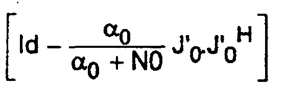
- We can take: where the weighted projection matrix is updated at relatively low frequency. It is the corrected vector h ⁇ X which is supplied to the module 11 for analyzing the channel.
- the interference direction J ' 0 is supplied to a module 18 which projects the output vector y and of the matched filter 12 onto a subspace orthogonal to J' 0 , which gives rise to a corrected vector y ⁇ .
- the correction consists in subtracting from y and a vector proportional to its projection in the direction J ' 0 .
- the method is also applicable in the case where the base station has several separate receiving antennas, the signals of which are combined to provide spatial diversity.
- the subspace described by the main interferer for a Q channel
- the weighted projection matrix of the relation (8) becomes: where ⁇ is the correlation factor between the two antennas.
Landscapes
- Engineering & Computer Science (AREA)
- Computer Networks & Wireless Communication (AREA)
- Signal Processing (AREA)
- Mobile Radio Communication Systems (AREA)
- Radio Relay Systems (AREA)
- Noise Elimination (AREA)
Description
- la figure 1 est un schéma synoptique de la partie réception d'une station de base selon l'invention ; et
- les figures 2 et 3 sont des schémas synoptiques de récepteurs appartenant à la station de base de la figure 1.
- calcul de l'espérance mathématique K de la matrice X.XH sur une durée typique de l'ordre de la centaine de millisecondes ;
- diagonalisation de la matrice K, et sélection des L valeurs propres de plus grands modules λi (0 ≤ i < L, avec |λ0| ≥ |λ1| ≥ ... ≥ |λL-1|), respectivement associées à des vecteurs propres vi;
- projection du vecteur X sur chacun des vecteurs propres retenus vi, pour obtenir les amplitudes ai. Ces amplitudes peuvent être obtenues par une projection simple (ai = vi H.X), ou par une projection pondérée pour réaliser l'estimation selon le critère du maximum a posteriori (MAP : ai = λi / λi + N0.vi H.X, N0 désignant une estimation de la puissance du bruit sur le canal). D'autres méthodes d'estimations connues sont encore utilisables (estimation au sens des moindres carrés, sous contrainte nulle, ...) ;
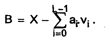
- calcul de la puissance du bruit N0 égale à l'espérance mathématique de
l'énergie par bit |B|2 du bruit résiduel
- h est un vecteur de dimension W contenant la réponse impulsionnelle du canal entre le terminal et la station de base, échantillonnée à la cadence des chips ;
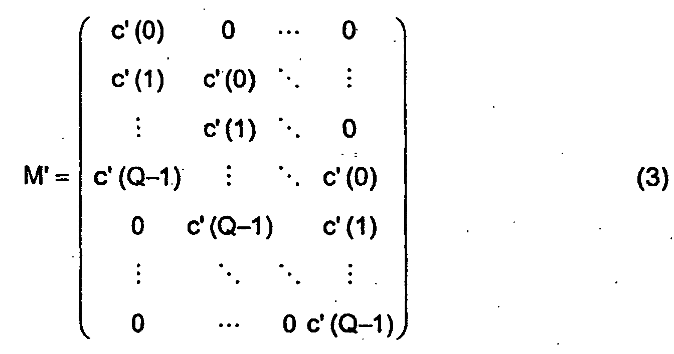
- M et M' sont des matrices de Toeplitz à Q+W-1 lignes et W colonnes,
dont les colonnes sont définies par les codes d'étalement
c = [c(0), c(1), ..., c(Q-1)] et c' = [c'(0), c'(1),.... c'(Q-1)] utilisés par
le terminal sur la voie Q et sur la voie l, respectivement :

- n est un vecteur contenant des échantillons de bruit additif. Ce bruit n'est pas nécessairement un bruit blanc car il comporte les contributions des autres canaux, issus des autres terminaux émettant en même temps.




Claims (10)
- Procédé de traitement de signal dans une station de base d'un système de radiocommunication à accès multiple à répartition par codes, dans lequel on soumet un premier signal (rQ) reçu par la station de base à un ensemble de filtres (13) adaptés à des codes d'étalement alloués à des canaux pilotes en provenance de terminaux radio respectifs, et on traite des vecteurs de sortie (h and1,h and) des filtres adaptés pour estimer des paramètres représentant lesdits canaux, les paramètres estimés pour un canal en provenance d'un terminal radio comprenant des vecteurs propres (v1,i, vi) représentant des trajets de propagation entre ledit terminal radio et la station de base, respectivement associés à des amplitudes (a1,i, ai) de réception suivant lesdits trajets, caractérisé en ce que le traitement des vecteurs de sortie des filtres adaptés comprend une estimation de paramètres (v1,i, a1,i) pour au moins un premier canal sur la base du vecteur de sortie (h and1) d'un premier filtre adapté au code d'étalement alloué audit premier canal, une modification du vecteur de sortie (h and) d'un second filtre adapté au code d'étalement alloué à au moins un second canal, le vecteur de sortie du second filtre adapté étant en moyenne moins énergétique que le vecteur de sortie du premier filtre adapté, et une estimation de paramètres (vi, ai) pour ledit second canal sur la base du vecteur de sortie modifié (h⊥) du second filtre adapté, et en ce que la modification du vecteur de sortie du second filtre adapté comporte au moins une soustraction d'un vecteur proportionnel à une projection dudit vecteur de sortie du second filtre adapté parallèlement à un vecteur de la forme MH.M1.v1,i, où M1 et M sont des matrices déterminées par les codes d'étalement respectivement alloués auxdits premier et second canaux, v1,i est un des vecteurs propres estimés pour le premier canal, et (.)H désigne le transposé conjugué.
- Procédé selon la revendication 1, dans lequel ledit vecteur propre v1,i est le vecteur propre estimé pour le premier canal qui est associé à l'amplitude dont le module est en moyenne le plus élevé.
- Procédé selon l'une quelconque des revendications précédentes, dans lequel les matrices M1 et M sont des matrices de Toeplitz dont les colonnes sont données par les codes d'étalement respectivement alloués aux premier et second canaux, en tenant compte d'un décalage temporel entre les premier et second canaux.
- Procédé selon l'une quelconque des revendications précédentes, dans lequel ledit vecteur soustrait est donné par αi / αi+N0 JiJi H.h and, où h and est le vecteur de sortie du second filtre adapté, Ji = 1 / Q.MH.M1.v1,i, Q est le facteur d'étalement sur les canaux pilotes, αi est une puissance moyenne de réception suivant le trajet de propagation représenté par.le vecteur propre v1,i et N0 est une puissance de bruit estimée sur le second canal.
- Procédé selon l'une quelconque des revendications précédentes, dans lequel chacun desdits canaux pilotes est formé conjointement à un canal de données en quadrature issu du même terminal radio, dans lequel on soumet un second signal (rl), reçu par la station de base en quadrature de phase par rapport audit premier signal (rQ), à un second ensemble de filtres (12) adaptés à des codes d'étalement respectivement alloués aux canaux de données en provenance des terminaux radio, on modifie certains au moins des vecteurs de sortie (y and) des filtres adaptés du second ensemble, et on estime des symboles d'information transmis sur un canal de données en provenance d'un terminal radio en soumettant le vecteur de sortie modifié (y⊥) du second filtre adapté au code d'étalement alloué audit canal de données à un récepteur en râteau (10) défini par les paramètres (vi, ai) estimés pour le canal pilote en provenance dudit terminal radio, et dans lequel la modification du vecteur de sortie dudit filtre adapté du second ensemble comporte au moins une soustraction d'un vecteur proportionnel à une projection dudit vecteur de sortie parallèlement à un vecteur de la forme M'H.M1.v1,i, où M' est une matrice déterminée par le code d'étalement alloué audit canal de données.
- Dispositif de traitement de signal dans une station de base d'un système de radiocommunication à accès multiple à répartition par codes, comprenant un ensemble de filtres (13) adaptés à des codes d'étalement alloués à des canaux pilotes en provenance de terminaux radio respectifs, pour recevoir un premier signal (rl) reçu par la station de base, et des moyens (11, 17) de traitement de vecteurs de sortie des filtres adaptés pour estimer des paramètres représentant lesdits canaux, les paramètres estimés pour un canal en provenance d'un terminal radio comprenant des vecteurs propres (v1,i, vi) représentant des trajets de propagation entre ledit terminal radio et la station de base, respectivement associés à des amplitudes (a1,i, ai) de réception suivant lesdits trajets, caractérisé en ce que lesdits moyens de traitement comprennent des moyens (11) d'estimation de paramètres (v1,i, a1,i) pour au moins un premier canal sur la base du vecteur de sortie (h and1) d'un premier filtre adapté au code d'étalement alloué audit premier canal, des moyens (17) de modification du vecteur de sortie (h and) d'un second filtre adapté au code d'étalement alloué à au moins un second canal, le vecteur de sortie du second filtre adapté étant en moyenne moins énergétique que le vecteur de sortie du premier filtre adapté, et des moyens (11 ) d'estimation de paramètres (vi, ai) pour ledit second canal sur la base du vecteur de sortie modifié (h⊥) du second filtre adapté, les moyens de modification étant agencés pour soustraire du vecteur de sortie du second filtre adapté au moins un vecteur proportionnel à une projection dudit vecteur de sortie du second filtre adapté parallèlement à un vecteur de la forme MH.M1.v1,i, où M1 et M sont des matrices déterminées par les codes d'étalement respectivement alloués auxdits premier et second canaux, v1,i est un des vecteurs propres estimés pour le premier canal, et (.)H désigne le transposé conjugué.
- Dispositif selon la revendication 6, dans lequel ledit vecteur propre v1,i est le vecteur propre estimé pour le premier canal qui est associé à l'amplitude dont le module est en moyenne le plus élevé.
- Dispositif selon la revendication 6 ou 7, dans lequel les matrices M1 et M sont des matrices de Toeplitz dont les colonnes sont données par les codes d'étalement respectivement alloués aux premier et second canaux, en tenant compte d'un décalage temporel entre les premier et second canaux.
- Dispositif selon l'une quelconque des revendications 6 à 8, dans lequel ledit vecteur soustrait est donné par αi / αi + N0 JiJi H.h and, où h and est le vecteur de sortie du second filtre adapté, Ji = 1 / (Q).MH.M1.v1,i, Q est le facteur d'étalement sur les canaux pilotes, αi est une puissance moyenne de réception suivant le trajet de propagation représenté par le vecteur propre v1,i et N0 est une puissance de bruit estimée sur le second canal.
- Dispositif selon l'une quelconque des revendications 6 à 9, comprenant en outre un second ensemble de filtres (12) adaptés à des codes d'étalement respectivement alloués à des canaux de données formés conjointement aux canaux pilotes en provenance des terminaux radio, pour recevoir un second signal (rl) reçu par la station de base en quadrature de phase par rapport audit premier signal (rQ), des moyens (18) de modification de certains au moins des vecteurs de sortie (y and) des filtres adaptés du second ensemble, et des moyens d'estimation de symboles d'information transmis sur au moins un canal de données en provenance d'un terminal radio, incluant un récepteur en râteau (10) défini par les paramètres (vi, ai) estimés pour le canal pilote en provenance dudit terminal radio et recevant le vecteur de sortie modifié (y⊥) ) du second filtre adapté au code d'étalement alloué audit canal de données, et dans lequel les moyens de modification du vecteur de sortie d'un filtre adapté du second ensemble comportent des moyens de soustraction d'un vecteur proportionnel à une projection dudit vecteur de sortie parallèlement à un vecteur de la forme M'H.M1.v1,i, où M' est une matrice déterminée par le code d'étalement alloué audit canal de données.
Applications Claiming Priority (2)
| Application Number | Priority Date | Filing Date | Title |
|---|---|---|---|
| FR0107399 | 2001-06-06 | ||
| FR0107399A FR2825856B1 (fr) | 2001-06-06 | 2001-06-06 | Procede et dispositif de traitement de signal dans un recepteur de radiocommunication a etalement de spectre |
Publications (3)
| Publication Number | Publication Date |
|---|---|
| EP1265374A2 EP1265374A2 (fr) | 2002-12-11 |
| EP1265374A3 EP1265374A3 (fr) | 2002-12-18 |
| EP1265374B1 true EP1265374B1 (fr) | 2003-12-17 |
Family
ID=8864016
Family Applications (1)
| Application Number | Title | Priority Date | Filing Date |
|---|---|---|---|
| EP02291319A Expired - Lifetime EP1265374B1 (fr) | 2001-06-06 | 2002-05-30 | Procédé et dispositif de traitement de signal dans un récepteur de radiocommunication à étalement de spectre |
Country Status (5)
| Country | Link |
|---|---|
| US (1) | US7184465B2 (fr) |
| EP (1) | EP1265374B1 (fr) |
| AT (1) | ATE256938T1 (fr) |
| DE (1) | DE60200137T2 (fr) |
| FR (1) | FR2825856B1 (fr) |
Families Citing this family (9)
| Publication number | Priority date | Publication date | Assignee | Title |
|---|---|---|---|---|
| JP4557331B2 (ja) * | 1999-05-20 | 2010-10-06 | キヤノン株式会社 | 情報処理装置、情報処理システム、動作制御方法、及びコンピュータ読み取り可能な記録媒体 |
| KR20050039883A (ko) * | 1999-09-21 | 2005-04-29 | 인터디지탈 테크날러지 코포레이션 | 가변 확산 인자용 멀티유저 검출기 |
| US6714527B2 (en) * | 1999-09-21 | 2004-03-30 | Interdigital Techology Corporation | Multiuser detector for variable spreading factors |
| FR2810820B1 (fr) * | 2000-06-22 | 2002-09-20 | Nortel Matra Cellular | Procede et dispositif de reception d'un signal radio |
| FR2853170A1 (fr) * | 2003-03-31 | 2004-10-01 | Nortel Networks Ltd | Procede de traitement d'un signal par un recepteur radio et recepteur radio pour la mise en oeuvre du procede |
| US7623596B2 (en) * | 2003-06-27 | 2009-11-24 | Ericsson, Inc. | Methods and systems for estimating a channel response by applying bias to an initial channel estimate |
| US7200190B2 (en) * | 2003-06-30 | 2007-04-03 | Motorola, Inc. | Unbiased signal to interference ratio in wireless communications devices and methods therefor |
| CN100512053C (zh) * | 2005-05-24 | 2009-07-08 | 上海原动力通信科技有限公司 | 一种确定时分同步码分多址系统用户信道冲激响应的方法 |
| US20230093484A1 (en) * | 2021-09-23 | 2023-03-23 | Apple Inc. | Systems and methods for de-correlating coded signals in dual port transmissions |
Family Cites Families (8)
| Publication number | Priority date | Publication date | Assignee | Title |
|---|---|---|---|---|
| US6157811A (en) * | 1994-01-11 | 2000-12-05 | Ericsson Inc. | Cellular/satellite communications system with improved frequency re-use |
| FI96651C (fi) * | 1994-08-25 | 1996-07-25 | Nokia Telecommunications Oy | Vastaanottomenetelmä ja vastaanotin |
| US6470044B1 (en) * | 1999-01-15 | 2002-10-22 | Sharp Laboratories Of America, Inc. | Computationally parsimonious forward link receiver for DS-CDMA systems and method for same |
| JP2000261412A (ja) * | 1999-03-06 | 2000-09-22 | Matsushita Electric Ind Co Ltd | 干渉信号除去装置 |
| US20020154705A1 (en) * | 2000-03-22 | 2002-10-24 | Walton Jay R. | High efficiency high performance communications system employing multi-carrier modulation |
| US7289570B2 (en) * | 2000-04-10 | 2007-10-30 | Texas Instruments Incorporated | Wireless communications |
| US7120657B2 (en) * | 2000-08-29 | 2006-10-10 | Science Applications International Corporation | System and method for adaptive filtering |
| US7027523B2 (en) * | 2001-06-22 | 2006-04-11 | Qualcomm Incorporated | Method and apparatus for transmitting data in a time division duplexed (TDD) communication system |
-
2001
- 2001-06-06 FR FR0107399A patent/FR2825856B1/fr not_active Expired - Fee Related
-
2002
- 2002-05-30 DE DE60200137T patent/DE60200137T2/de not_active Expired - Fee Related
- 2002-05-30 EP EP02291319A patent/EP1265374B1/fr not_active Expired - Lifetime
- 2002-05-30 AT AT02291319T patent/ATE256938T1/de not_active IP Right Cessation
- 2002-06-05 US US10/164,129 patent/US7184465B2/en not_active Expired - Fee Related
Also Published As
| Publication number | Publication date |
|---|---|
| DE60200137D1 (de) | 2004-01-29 |
| ATE256938T1 (de) | 2004-01-15 |
| FR2825856B1 (fr) | 2003-09-12 |
| EP1265374A3 (fr) | 2002-12-18 |
| FR2825856A1 (fr) | 2002-12-13 |
| EP1265374A2 (fr) | 2002-12-11 |
| US7184465B2 (en) | 2007-02-27 |
| US20030043893A1 (en) | 2003-03-06 |
| DE60200137T2 (de) | 2004-09-02 |
Similar Documents
| Publication | Publication Date | Title |
|---|---|---|
| EP0735702B1 (fr) | Procédé et dispositif de réception multicapteur d'une station de base fixe pour un système de communication mobile | |
| JP3202754B2 (ja) | 複数の多重アクセス伝送の処理方法 | |
| FR2706709A1 (fr) | Procédé de synchronisation pour des communications radiotéléphoniques à accès multiple à répartition par codes. | |
| US20040042531A1 (en) | System and method for CDMA communications | |
| FR2827445A1 (fr) | Dispositif et procede pour maximiser le rendement d'un amplificateur de puissance d'une station de base dans un systeme de communication mobile | |
| WO1997008849A1 (fr) | Procede et dispositif de multiplexage/demultiplexage spatial de signaux radioelectriques pour systeme radio mobile sdma | |
| EP1260071B1 (fr) | Procede et dispositif d'estimation d'un canal de propagation | |
| EP1265374B1 (fr) | Procédé et dispositif de traitement de signal dans un récepteur de radiocommunication à étalement de spectre | |
| EP1187366B1 (fr) | Récepteur CDMA adaptif uni-modulaire | |
| EP0643504A1 (fr) | Détecteur à seuil pour système à AMRC | |
| EP3900199A1 (fr) | Système de communication par rétrodiffusion ambiante, appareil et procédé associés | |
| EP1105975B1 (fr) | Recepteur en rateau iteratif et procede de reception correspondant | |
| EP0820157B1 (fr) | Procédé de démodulation différentielle numérique | |
| US20050118955A1 (en) | Method for prediction of a channel coefficient | |
| FR2851098A1 (fr) | Procede de traitement d'un signal par un recepteur radio et recepteur radio pour la mise en oeuvre du procede | |
| EP1235399B1 (fr) | Procédé et dispositif d'estimation de la matrice de covariance du canal de transmission d'un système UMTS | |
| EP1910862B1 (fr) | Appareil et procede d'estimation de delai | |
| EP1623514B1 (fr) | Modulateur et demodulateur a etalement de spectre | |
| EP1240759B1 (fr) | Dispositifs d'estimation de canal radio et de demodulation | |
| FR2882479A1 (fr) | Procede et dispositif de synchronisation de liaisons rectilignes ou quasi-rectilignes en presence d'interferences | |
| EP1280286B1 (fr) | Station radio à diversité d'émission en boucle fermée, et procédé de contrôle d'émission d'une telle station | |
| FR2818835A1 (fr) | Procede et dispositif de traitement de signal dans un recepteur de radiocommunication a etalement de spectre | |
| EP1221792A1 (fr) | Procédé et récepteur autodidacte pour déterminer les paramètres spatio-temporels d'un canal de propagation | |
| WO2005088999A1 (fr) | Procede d'optimisation de la planification dans un systeme de communications de type cdma | |
| EP1292047B1 (fr) | Procédé et dispositif de détection de sources dans un système de communications |
Legal Events
| Date | Code | Title | Description |
|---|---|---|---|
| PUAI | Public reference made under article 153(3) epc to a published international application that has entered the european phase |
Free format text: ORIGINAL CODE: 0009012 |
|
| PUAL | Search report despatched |
Free format text: ORIGINAL CODE: 0009013 |
|
| AK | Designated contracting states |
Kind code of ref document: A2 Designated state(s): AT BE CH CY DE DK ES FI FR GB GR IE IT LI LU MC NL PT SE TR |
|
| AX | Request for extension of the european patent |
Free format text: AL;LT;LV;MK;RO;SI |
|
| AK | Designated contracting states |
Kind code of ref document: A3 Designated state(s): AT BE CH CY DE DK ES FI FR GB GR IE IT LI LU MC NL PT SE TR |
|
| AX | Request for extension of the european patent |
Free format text: AL;LT;LV;MK;RO;SI |
|
| 17P | Request for examination filed |
Effective date: 20021125 |
|
| GRAP | Despatch of communication of intention to grant a patent |
Free format text: ORIGINAL CODE: EPIDOSNIGR1 |
|
| AKX | Designation fees paid |
Designated state(s): AT BE CH CY DE DK ES FI FR GB GR IE IT LI LU MC NL PT SE TR |
|
| GRAS | Grant fee paid |
Free format text: ORIGINAL CODE: EPIDOSNIGR3 |
|
| GRAA | (expected) grant |
Free format text: ORIGINAL CODE: 0009210 |
|
| AK | Designated contracting states |
Kind code of ref document: B1 Designated state(s): AT BE CH CY DE DK ES FI FR GB GR IE IT LI LU MC NL PT SE TR |
|
| PG25 | Lapsed in a contracting state [announced via postgrant information from national office to epo] |
Ref country code: IT Free format text: LAPSE BECAUSE OF FAILURE TO SUBMIT A TRANSLATION OF THE DESCRIPTION OR TO PAY THE FEE WITHIN THE PRESCRIBED TIME-LIMIT;WARNING: LAPSES OF ITALIAN PATENTS WITH EFFECTIVE DATE BEFORE 2007 MAY HAVE OCCURRED AT ANY TIME BEFORE 2007. THE CORRECT EFFECTIVE DATE MAY BE DIFFERENT FROM THE ONE RECORDED. Effective date: 20031217 Ref country code: CY Free format text: LAPSE BECAUSE OF FAILURE TO SUBMIT A TRANSLATION OF THE DESCRIPTION OR TO PAY THE FEE WITHIN THE PRESCRIBED TIME-LIMIT Effective date: 20031217 Ref country code: TR Free format text: LAPSE BECAUSE OF FAILURE TO SUBMIT A TRANSLATION OF THE DESCRIPTION OR TO PAY THE FEE WITHIN THE PRESCRIBED TIME-LIMIT Effective date: 20031217 Ref country code: FI Free format text: LAPSE BECAUSE OF FAILURE TO SUBMIT A TRANSLATION OF THE DESCRIPTION OR TO PAY THE FEE WITHIN THE PRESCRIBED TIME-LIMIT Effective date: 20031217 Ref country code: AT Free format text: LAPSE BECAUSE OF FAILURE TO SUBMIT A TRANSLATION OF THE DESCRIPTION OR TO PAY THE FEE WITHIN THE PRESCRIBED TIME-LIMIT Effective date: 20031217 Ref country code: NL Free format text: LAPSE BECAUSE OF FAILURE TO SUBMIT A TRANSLATION OF THE DESCRIPTION OR TO PAY THE FEE WITHIN THE PRESCRIBED TIME-LIMIT Effective date: 20031217 Ref country code: IE Free format text: LAPSE BECAUSE OF FAILURE TO SUBMIT A TRANSLATION OF THE DESCRIPTION OR TO PAY THE FEE WITHIN THE PRESCRIBED TIME-LIMIT Effective date: 20031217 |
|
| REG | Reference to a national code |
Ref country code: GB Ref legal event code: FG4D Free format text: NOT ENGLISH |
|
| REG | Reference to a national code |
Ref country code: CH Ref legal event code: EP |
|
| REG | Reference to a national code |
Ref country code: IE Ref legal event code: FG4D Free format text: FRENCH |
|
| REF | Corresponds to: |
Ref document number: 60200137 Country of ref document: DE Date of ref document: 20040129 Kind code of ref document: P |
|
| PG25 | Lapsed in a contracting state [announced via postgrant information from national office to epo] |
Ref country code: DK Free format text: LAPSE BECAUSE OF FAILURE TO SUBMIT A TRANSLATION OF THE DESCRIPTION OR TO PAY THE FEE WITHIN THE PRESCRIBED TIME-LIMIT Effective date: 20040317 Ref country code: SE Free format text: LAPSE BECAUSE OF FAILURE TO SUBMIT A TRANSLATION OF THE DESCRIPTION OR TO PAY THE FEE WITHIN THE PRESCRIBED TIME-LIMIT Effective date: 20040317 Ref country code: GR Free format text: LAPSE BECAUSE OF FAILURE TO SUBMIT A TRANSLATION OF THE DESCRIPTION OR TO PAY THE FEE WITHIN THE PRESCRIBED TIME-LIMIT Effective date: 20040317 |
|
| PG25 | Lapsed in a contracting state [announced via postgrant information from national office to epo] |
Ref country code: ES Free format text: LAPSE BECAUSE OF FAILURE TO SUBMIT A TRANSLATION OF THE DESCRIPTION OR TO PAY THE FEE WITHIN THE PRESCRIBED TIME-LIMIT Effective date: 20040328 |
|
| GBT | Gb: translation of ep patent filed (gb section 77(6)(a)/1977) |
Effective date: 20040308 |
|
| PGFP | Annual fee paid to national office [announced via postgrant information from national office to epo] |
Ref country code: DE Payment date: 20040528 Year of fee payment: 3 |
|
| PG25 | Lapsed in a contracting state [announced via postgrant information from national office to epo] |
Ref country code: LU Free format text: LAPSE BECAUSE OF NON-PAYMENT OF DUE FEES Effective date: 20040530 |
|
| PG25 | Lapsed in a contracting state [announced via postgrant information from national office to epo] |
Ref country code: MC Free format text: LAPSE BECAUSE OF NON-PAYMENT OF DUE FEES Effective date: 20040531 Ref country code: BE Free format text: LAPSE BECAUSE OF NON-PAYMENT OF DUE FEES Effective date: 20040531 |
|
| NLV1 | Nl: lapsed or annulled due to failure to fulfill the requirements of art. 29p and 29m of the patents act | ||
| REG | Reference to a national code |
Ref country code: IE Ref legal event code: FD4D |
|
| PLBE | No opposition filed within time limit |
Free format text: ORIGINAL CODE: 0009261 |
|
| STAA | Information on the status of an ep patent application or granted ep patent |
Free format text: STATUS: NO OPPOSITION FILED WITHIN TIME LIMIT |
|
| BERE | Be: lapsed |
Owner name: *NORTEL NETWORKS LTD Effective date: 20040531 |
|
| 26N | No opposition filed |
Effective date: 20040920 |
|
| PG25 | Lapsed in a contracting state [announced via postgrant information from national office to epo] |
Ref country code: DE Free format text: LAPSE BECAUSE OF NON-PAYMENT OF DUE FEES Effective date: 20051201 |
|
| PG25 | Lapsed in a contracting state [announced via postgrant information from national office to epo] |
Ref country code: CH Free format text: LAPSE BECAUSE OF NON-PAYMENT OF DUE FEES Effective date: 20060531 Ref country code: LI Free format text: LAPSE BECAUSE OF NON-PAYMENT OF DUE FEES Effective date: 20060531 |
|
| REG | Reference to a national code |
Ref country code: CH Ref legal event code: PL |
|
| PG25 | Lapsed in a contracting state [announced via postgrant information from national office to epo] |
Ref country code: PT Free format text: LAPSE BECAUSE OF NON-PAYMENT OF DUE FEES Effective date: 20040517 |
|
| PGFP | Annual fee paid to national office [announced via postgrant information from national office to epo] |
Ref country code: GB Payment date: 20080522 Year of fee payment: 7 |
|
| REG | Reference to a national code |
Ref country code: GB Ref legal event code: 732E Free format text: REGISTERED BETWEEN 20091112 AND 20091118 |
|
| GBPC | Gb: european patent ceased through non-payment of renewal fee |
Effective date: 20090530 |
|
| REG | Reference to a national code |
Ref country code: FR Ref legal event code: ST Effective date: 20100129 |
|
| PG25 | Lapsed in a contracting state [announced via postgrant information from national office to epo] |
Ref country code: FR Free format text: LAPSE BECAUSE OF NON-PAYMENT OF DUE FEES Effective date: 20090602 |
|
| PGFP | Annual fee paid to national office [announced via postgrant information from national office to epo] |
Ref country code: FR Payment date: 20080526 Year of fee payment: 7 |
|
| PG25 | Lapsed in a contracting state [announced via postgrant information from national office to epo] |
Ref country code: GB Free format text: LAPSE BECAUSE OF NON-PAYMENT OF DUE FEES Effective date: 20090530 |