EP1265383A2 - Optisches Übertragungssystem - Google Patents
Optisches Übertragungssystem Download PDFInfo
- Publication number
- EP1265383A2 EP1265383A2 EP02253954A EP02253954A EP1265383A2 EP 1265383 A2 EP1265383 A2 EP 1265383A2 EP 02253954 A EP02253954 A EP 02253954A EP 02253954 A EP02253954 A EP 02253954A EP 1265383 A2 EP1265383 A2 EP 1265383A2
- Authority
- EP
- European Patent Office
- Prior art keywords
- optical
- fiber
- connector
- pair
- terminal
- Prior art date
- Legal status (The legal status is an assumption and is not a legal conclusion. Google has not performed a legal analysis and makes no representation as to the accuracy of the status listed.)
- Withdrawn
Links
Images
Classifications
-
- H—ELECTRICITY
- H04—ELECTRIC COMMUNICATION TECHNIQUE
- H04B—TRANSMISSION
- H04B10/00—Transmission systems employing electromagnetic waves other than radio-waves, e.g. infrared, visible or ultraviolet light, or employing corpuscular radiation, e.g. quantum communication
- H04B10/27—Arrangements for networking
-
- H—ELECTRICITY
- H04—ELECTRIC COMMUNICATION TECHNIQUE
- H04B—TRANSMISSION
- H04B10/00—Transmission systems employing electromagnetic waves other than radio-waves, e.g. infrared, visible or ultraviolet light, or employing corpuscular radiation, e.g. quantum communication
- H04B10/27—Arrangements for networking
- H04B10/272—Star-type networks or tree-type networks
-
- H—ELECTRICITY
- H04—ELECTRIC COMMUNICATION TECHNIQUE
- H04J—MULTIPLEX COMMUNICATION
- H04J14/00—Optical multiplex systems
- H04J14/02—Wavelength-division multiplex systems
- H04J14/0227—Operation, administration, maintenance or provisioning [OAMP] of WDM networks, e.g. media access, routing or wavelength allocation
-
- H—ELECTRICITY
- H04—ELECTRIC COMMUNICATION TECHNIQUE
- H04J—MULTIPLEX COMMUNICATION
- H04J14/00—Optical multiplex systems
- H04J14/02—Wavelength-division multiplex systems
- H04J14/0227—Operation, administration, maintenance or provisioning [OAMP] of WDM networks, e.g. media access, routing or wavelength allocation
- H04J14/0241—Wavelength allocation for communications one-to-one, e.g. unicasting wavelengths
- H04J14/0242—Wavelength allocation for communications one-to-one, e.g. unicasting wavelengths in WDM-PON
- H04J14/0245—Wavelength allocation for communications one-to-one, e.g. unicasting wavelengths in WDM-PON for downstream transmission, e.g. optical line terminal [OLT] to ONU
- H04J14/0246—Wavelength allocation for communications one-to-one, e.g. unicasting wavelengths in WDM-PON for downstream transmission, e.g. optical line terminal [OLT] to ONU using one wavelength per ONU
-
- H—ELECTRICITY
- H04—ELECTRIC COMMUNICATION TECHNIQUE
- H04J—MULTIPLEX COMMUNICATION
- H04J14/00—Optical multiplex systems
- H04J14/02—Wavelength-division multiplex systems
- H04J14/0227—Operation, administration, maintenance or provisioning [OAMP] of WDM networks, e.g. media access, routing or wavelength allocation
- H04J14/0241—Wavelength allocation for communications one-to-one, e.g. unicasting wavelengths
- H04J14/0242—Wavelength allocation for communications one-to-one, e.g. unicasting wavelengths in WDM-PON
- H04J14/0245—Wavelength allocation for communications one-to-one, e.g. unicasting wavelengths in WDM-PON for downstream transmission, e.g. optical line terminal [OLT] to ONU
- H04J14/0247—Sharing one wavelength for at least a group of ONUs
-
- H—ELECTRICITY
- H04—ELECTRIC COMMUNICATION TECHNIQUE
- H04J—MULTIPLEX COMMUNICATION
- H04J14/00—Optical multiplex systems
- H04J14/02—Wavelength-division multiplex systems
- H04J14/0227—Operation, administration, maintenance or provisioning [OAMP] of WDM networks, e.g. media access, routing or wavelength allocation
- H04J14/0241—Wavelength allocation for communications one-to-one, e.g. unicasting wavelengths
- H04J14/0242—Wavelength allocation for communications one-to-one, e.g. unicasting wavelengths in WDM-PON
- H04J14/0249—Wavelength allocation for communications one-to-one, e.g. unicasting wavelengths in WDM-PON for upstream transmission, e.g. ONU-to-OLT or ONU-to-ONU
- H04J14/025—Wavelength allocation for communications one-to-one, e.g. unicasting wavelengths in WDM-PON for upstream transmission, e.g. ONU-to-OLT or ONU-to-ONU using one wavelength per ONU, e.g. for transmissions from-ONU-to-OLT or from-ONU-to-ONU
-
- H—ELECTRICITY
- H04—ELECTRIC COMMUNICATION TECHNIQUE
- H04J—MULTIPLEX COMMUNICATION
- H04J14/00—Optical multiplex systems
- H04J14/02—Wavelength-division multiplex systems
- H04J14/0227—Operation, administration, maintenance or provisioning [OAMP] of WDM networks, e.g. media access, routing or wavelength allocation
- H04J14/0241—Wavelength allocation for communications one-to-one, e.g. unicasting wavelengths
- H04J14/0242—Wavelength allocation for communications one-to-one, e.g. unicasting wavelengths in WDM-PON
- H04J14/0249—Wavelength allocation for communications one-to-one, e.g. unicasting wavelengths in WDM-PON for upstream transmission, e.g. ONU-to-OLT or ONU-to-ONU
- H04J14/0252—Sharing one wavelength for at least a group of ONUs, e.g. for transmissions from-ONU-to-OLT or from-ONU-to-ONU
-
- H—ELECTRICITY
- H04—ELECTRIC COMMUNICATION TECHNIQUE
- H04J—MULTIPLEX COMMUNICATION
- H04J14/00—Optical multiplex systems
- H04J14/02—Wavelength-division multiplex systems
- H04J14/0278—WDM optical network architectures
- H04J14/0282—WDM tree architectures
-
- H—ELECTRICITY
- H04—ELECTRIC COMMUNICATION TECHNIQUE
- H04J—MULTIPLEX COMMUNICATION
- H04J14/00—Optical multiplex systems
- H04J14/02—Wavelength-division multiplex systems
- H04J14/0287—Protection in WDM systems
- H04J14/0289—Optical multiplex section protection
- H04J14/0291—Shared protection at the optical multiplex section (1:1, n:m)
Definitions
- the present invention relates to methods and apparatus associated with broadband communications using optical fibers as the transmission media, and more specifically to methods and apparatus for on-demand upgrading of an existing optical network system with the capacity to service additional subscribers with broadband digital service with no installation of additional optical fibers and minimal replacement of existing infrastructure.
- Optical fibers have an extremely high bandwidth thereby allowing the transmission of significantly more information than can be carried by a copper wire.
- the carried information includes broadband digital data carrying digital television signals, computer data, etc.
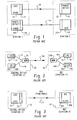
- fiber 10 is connected by an optical coupler 12 to an LED (light-emitting diode) 14 at one end and by optical coupler 16 to a PD (photodetection diode) 18 at the other end.
- fiber 10A is connected by an optical coupler 16A to PD 18 at one end and by optical coupler 12A to LED 14 at the other end.
- a single fiber is quite capable of carrying communications in both directions.
- WDM wavelength divisional multiplexing
- a central office 20 is connected to an immediate or RT (remote terminal) 22 by at least one pair of optical fibers 10B.
- the remote terminal 22 may be further connected to a multiplicity of destination terminals by other pairs of optical fibers.
- the central office includes a light-emitting diode 14 optically connected to fiber optics 10 by optical coupler 12 for converting electrical signals to optical signals and a photodetection diode 18A optically connected to optical fiber 10A by a coupler 16A for converting optical signals to electrical signals.
- the fiber optics 10 and fiber optics 10A are each connected to a wavelength division multiplexer 24 which in turn is connected by optical coupler 26 to optical fiber 10B. This arrangement is duplicated at the RDT 22 by light-emitting diode 14A, photodetection diode 18, and wavelength division multiplexer 24A.
- TCM time compression multiplexing
- Still other and more advanced systems carry telephony communication (either analog or digital) at one wavelength of light and television signals (digital and/or analog) at another wavelength.
- optical fibers have extremely high bandwidths and use of an optical fiber for any of the above-mentioned existing systems is a very ineffective use of the fiber and, in fact, the available bandwidth of an optical fiber makes it possible to use both active and passive optical transmission techniques which can be used to carry a significantly-increased number of individual bidirectional broadband communication channels or signals.
- the present invention seeks to provide apparatus for upgrading an optical communication transmission system so that it can carry a significantly-increased number of broadband bidirectional channels, without extensive installation of new optical fibers.
- apparatus for providing optical data transmission comprises a first optical device located in said intermediate terminal and having at least one input optical connector and an output optical connection; a second optical device located in said intermediate terminal having an input optical connector and at least one output optical connector; a transmission loop comprising a plurality of said selected destination
- apparatus for providing optical data transmission comprises a first conversion circuit located in said intermediate terminal having an input optical connector and an output optical connector said first conversion circuit for converting optical data to electrical data and electrical data to optical data, said first conversion circuitry further including electrical connections; a transmission loop comprising a plurality of
- apparatus for providing upgraded optical data transmission comprises a first conversion circuit located in said intermediate terminal having an output optical connector and an input optical connector for connecting said optical fibers to optically transmit and receive bidirectional data between said intermediate terminal and selected ones of said multiplicity of destination terminals, said first conversion circuit for converting optical data to electrical data and electrical data to optical data, said first optical conversion circuit further including electrical connections; a first and last OIU (optical interface unit) located in a first and last destination terminal, respectively, each of said first and last OIUs, including an input optical connector and an output optical connector, said OIUs for extracting and inserting data on lightwaves traveling over a pair of said
- apparatus for providing optical data transmission comprises a first optical device located in said intermediate terminal and having at least one input optical connector and an output optical connection; a second optical device located in said intermediate terminal having an input optical connector and at least one output optical connector; a transmission loop comprising a plurality of
- apparatus for providing optical data transmission comprises at least one optical coupler/splitter having a destination terminal side and a primary terminal side, said destination terminal side having at least two optical connectors, and said primary terminal side having at least one optical connector; a transmission loop comprising a plurality of said selected
- each first fiber of the plurality of pairs are connected to the output optical connectors of the OIU and the second fiber of each plurality of pairs are connected to the input optical connectors of the OIU.
- an intermediate distribution terminal 22 which is connected to optical communication equipment 40 at central office 20 by at least one primary pair of optical fibers 42, and preferably by two primary pairs of optical fibers 42 and 44. It is not uncommon for a spare pair of optical fibers to extend between an intermediate distribution terminal and a central office.
- Intermediate distribution terminal 22 is shown as including an optical splitter device 46 connected to one of the optical fibers 42a of fiber pair 42 and an optical combining device 48 connected to the other fiber 42b of fiber pair 42.
- optical splitter device 46 and optical combining device 48 may typically be devices having a ratio of 32:1. That is, the devices either receive light from or transmit light to thirty-two optical fibers, and this received or transmitted light is carried by a single fiber after either being split or combined, whichever is appropriate.
- splitter 46 receives light carrying information from fiber 42a of fiber pair 42 and splits the light into, for example only, thirty-two portions which are coupled to one of the fibers of thirty-two different pairs of fibers such as pairs 50, 52, 54, 56, 58, 60, 62 and 64 between intermediate terminal 22 and thirty-two destination terminals such as the thirty-two OIUs (optical interface unit), 66, 68, 70, 72, 74, 76, 78 and 80 found in thirty-two destination terminals at thirty-two different locations.
- OIUs optical interface unit
- combining device 48 located in intermediate terminal 22 receives light from the thirty-two OIUs on the other fiber of each of the fiber pairs 50 through 64, combines the received light and couples it to the single fiber 42b of fiber pair 42 such that it is transmitted to optical communication equipment 40 at central office 20.
- there are thirty-two separate OIUs which may be installed at thirty-two distinct and separate locations including OIU 66 through 80 which are connected by one of the fibers of each of the thirty-two pairs of optical fibers 50 through 64 to the optical splitter device 46 in intermediate terminal 22.
- the thirty-two OIUs are also connected by the other fiber of each pair to the optical combining or coupler unit 48 which is also located in intermediate terminal 22.
- the thirty-two OIUs, the thirty-two pairs of corresponding optical fibers and the 32:1 splitter unit 46 and 32:1 combining unit 48 represents a typical prior art passive optical network system. Also, as was discussed above with respect to individual fibers 42a and 42b which make up pair 42, it is not necessary that the individual fibers of the pairs 50 through 64 or any other pair of optical fibers discussed herein, run side by side in a common sheath. It is only necessary that the individual fibers in a pair start and terminate at the same locations. Other prior art systems may use equipment which supports a number of destination terminals and corresponding pairs of optical fibers which is different than thirty-two.
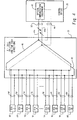
- FIG. 5 there is shown a first embodiment wherein an existing passive optical network such as was discussed with respect to FIG. 4 is suitable for being upgraded to an active optical network system for carrying broadband data signals.
- a primary pair of optical fibers 42 having individual fibers 42a and 42b extends between optical equipment 40 in the central office 20, and optical to electrical conversion equipment 82 in the intermediate distribution terminal 22.
- thirty-two corresponding pairs of optical fibers including the representative eight pairs of optical fibers 50 through 64 which extend between intermediate terminal 22 and thirty-two separate destination terminals, each of which in the embodiment of FIG.
- BOIU 5 contains a BOIU (broadband optical interface unit) such as represented by BOIUs 66a, 68a, 70a, 72a, 74a, 76a, 78a and 80a.
- BOIUs 66a, 68a, 70a, 72a, 74a, 76a, 78a and 80a In addition to optical/electrical data converting equipment 82 located in intermediate terminal 22, there are also included optical communication units such as units 84 and 86 each of which includes an output optical connector 88 and an input optical connector 90.
- a pair of optical fibers extend between the intermediate terminal 22 and each of the BOIUs 66a through 80a.
- the pair of optical fibers 50 include a first fiber 92 and second fiber 94, and as a further example, and only for convenience, the first fiber 92 is shown carrying light from to intermediate terminal 22 to BOIU 66a whereas the second fiber 94 is shown carrying light in the opposite direction from the BOIU 66a to intermediate terminal 22.
- the first fiber 92 of optical pair 50 includes a "first" optical connector at the intermediate end of fiber 92 such as optical connector 96 at the end of optical fiber 92 which terminates in intermediate terminal 22.
- optical connector 98 on the destination terminal end of fiber 92 which terminates at BOIU 66a.
- the second optical fiber 94 includes a "second" connector on the intermediate terminal 22 end of fiber 94 such as optical connector 100 at the end of optical fiber 94 and optical connector 102 on the other end which terminates at BOIU 66a.
- BOIU 66a includes an input optical connector 104 and an output optical connector 106 which are connected to optical connectors 98 and 102, respectively.
- the optical pair 52 which extends between BOIU 68a and intermediate terminal 22 also includes a first optical fiber 108 having a "first" optical connector 110 at the end of fiber 108 which terminates in intermediate terminal 22 and an optical connector 112 at the end of fiber 108 which terminates at BOIU 68a.
- the second optical fiber 114 of optical pair 52 includes a "second" optical connector 116 on the end which terminates at intermediate terminal 22 and optical connector 118 on the end of optical fiber 114 which terminates at the BOIU 68a.
- BOIU 68a also includes an input terminal 120 and an output terminal 122.
- FIGS. 5 and 6 it is seen that lightwaves carrying data information is provided at connector 88 of optical equipment 84.
- optical connector 96 of fiber 92 When optical connector 96 of fiber 92 is connected to optical connector 88 of optical equipment 84, light is provided from the unit 84 through the "first" optical fiber 92 to the BOIU 66a through connector 98 on fiber 92 to input optical connector 104 on BOIU 66a.
- data carried on "first" optical fiber 92 which is appropriate for or "addressed to" BOIU 66a will be extracted from the traveling lightwaves and put in suitable format for further transmission or use.
- BOIU 66a In addition to extracting data from the light coming into BIOU 66 on optical fiber 92, BOIU 66a also inserts new data onto the light traveling through the unit which exits BIOU 66a on connector 106 to connector 102 and onto "second" fiber 94 of pair 50. Thus, new data inserted by BOIU 66a is now carried on “second" fiber 94 to connector 100 located in intermediate terminal 22. However, it is noticed that connector 100 is not connected to the optical equipment 84, but is instead connected to the "first" optical connector 110 on another "first” optical fiber 108 of fiber pair 52.
- FIG. 5 there are a plurality of units similar to optical equipment 84, each of which is connected to a transmission loop with four separate BOIUs in the same manner as just discussed.
- electrical equipment 86 in intermediate terminal 22 is part of the transmission loop made up by BOIU 74a, 76a, 78a and 80a along with corresponding optical fiber pairs 58, 60, 62 and 64.
- BOIU 74a, 76a, 78a and 80a along with corresponding optical fiber pairs 58, 60, 62 and 64.
- the number of BOIUs could be greater or less than four.
- one of the BOIU units may necessarily have to be taken out of the loop so that there might be only three BOIU units in the loop because of the increased traffic.
- the BOIU unit taken out of the overloaded transmission loop would then be combined into another transmission loop and perhaps with a new piece of optical equipment similar to that of optical equipment 84.
- each of the optical fiber pairs 50 through 56 are handling four times the number of channels because of the serial transmission loop than would be handled by each pair if each BOIU unit went to a separate piece of optical equipment such as optical equipment 84.
- FIG. 7 illustrate two embodiments for upgrading an optical system which does not require active elements, and only incorporates passive elements at the intermediate or remote distribution terminal.
- the embodiment of FIG. 7 use passive elements such as an optical coupler/splitter to combine various wavelengths of light arriving on a plurality of optical fibers such that all of the optical signals can be carried on a single optical fiber.
- passive elements such as an optical coupler/splitter to combine various wavelengths of light arriving on a plurality of optical fibers such that all of the optical signals can be carried on a single optical fiber.
- an optical coupler/splitter with CWDM continuous wave division multiplexing
- a single fiber may be used to carry light having a wavelength of 1,310 nanometers as is typically used for telephony service as well as four different wavelengths, such as 1,510, 1530, 1,550 and 1,570 rather than a single nominal wavelength of 1,550 nanometers.
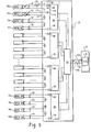
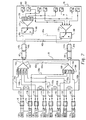
- central office 20 is connected to intermediate or remote distribution terminal 22 by at least two primary optical fibers such as optical fiber pair 42 which has individual fibers 42a and 42b.
- Intermediate terminal 22 is also connected to a plurality (such as thirty-two) of BOIU (broadband optical interface unit) by a like plurality of pairs of optical fibers.
- BOIU terminals 130 and 132 represent the first and eighth BOIUs forming a first optical loop of eight different BOIUs.
- the loop is connected by a corresponding eight pairs of optical fibers as represented by optical fiber pairs 134 and 136 in the same manner as the loop of four different BOIUs discussed with respect to FIGS. 5 and 6.
- the ninth BOIU 138 and the sixteenth BOIU 140, along with a first optical fiber pair 142 and an eighth optical fiber pair 144 represent a second optical loop of eight additional BOIUs and their corresponding eight pairs of optical fibers.
- each of the four optical data loops carry light at slightly different wavelengths.
- the optical loops 1, 2, 3 and 4 operate at 1,510, 1,530, 1,550 and 1,570 nanometers of light, respectively.
- intermediate or remote distribution terminal 22 also includes an optical combination device or coupler 162 having its output side optically connected to optical fiber 42a of optical pair 42.
- the four inputs of optical coupler 162 are fibers 134a from optical fiber pair 134, optical fiber 142a from fiber pair 142, optical fiber 150a from fiber pair 150 and optical fiber 158a from fiber pair 150.
- each of the four serial transmission loops has an input to the optical coupling device 162.
- the splitter/coupler 164 has its input 168 connected to optical fiber 42b of optical fiber 42.
- Each of the four outputs are connected to one output of the four-way filter 166 and are in turn connected one each to the last fiber of each of the four loops.
- fiber 136b from the first loop is connected to the filter 166 and then to splitter/coupler 164 and the optical fiber 144b from the second optical loop is also connected to filter 166 and then to coupler 164.
- optical fiber 152b from the third optical loop and optical fiber 160b from the fourth optical loop are connected through the filter 166 to the splitter/coupler 164.
- route protection switch such as switches 170 and 172 located between each of the BOIUs and their corresponding fiber optical pair.
- protection switch 170 is located between BOIU 130 and optical pair 134.
- route protection switch 172 is located between BOIU 132 and optical pair 136.
- the purpose of the route protection switches is that in the event a single BOIU, such as for example BOIU 130, were to fail, the route protection switch would operate to bypass that BOIU such that only the customers or subscribers associated with and receiving service through BOIU 30 would lose service.
- the fault protection switch simply bypasses BOIU 130 and couples the optical signal directly from the optical fiber 134a to optical fiber 134b of the optical pair 134.
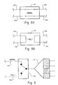
- FIGS. 8A and 8B illustrate the normal light path and the fault light path, respectively, through the fault protection switches. Thus, the seven remaining BOIUs can continue to cover and provide service without interruption.
- control office 20 includes an optical splitter/coupler 174 in combination with a CWDM filter 176 connected to optical fiber 42a of pair 42. Similarly, optical coupler/splitter 178 connected to optical fiber 42b of pair 42. Also as shown, there are four optical receivers and four optical transmitters such as receiver 180 and transmitter 182. Each of the four receivers and transmitters are for receiving and transmitting light having one of the four different wavelengths. Thus, each receiver such as receiver 180 is coupled to the wave division multiplexer filter 176 such that only light of the proper wavelength is directed to the proper receiver. Similarly, each transmitter is connected to optical coupler 178.
- redundancy may be provided such that if a fiber in the first primary pair 42 were to be cut or otherwise damaged, a fiber in the second fiber pair 184 can take over.
- This is accomplished by a pair of route protection switches 186 and 188 which are connected so that if, for example, fiber 42a of pair 42 were to be damaged or separated, switch 186 would activate such that the input of the optical coupler/splitter 174 would be connected to optical fiber 184a of fiber pair 184 rather than fiber 42a of pair 42.
- FIG. 9 illustrates the normal and fault positions of the route protection switches. It should be also be noted, however, that this alternate embodiment also requires that the optical coupler/splitter 162 and 164 discussed with respect to intermediate terminal 22 should have two outputs rather than a single output as was discussed before. That is, the optical coupler/splitters should be a 4:2 rather than a 4:1 splitter/coupler. Thus, it is seen there has been described a method of using existing fiber optical pairs to upgrade a system to a passive system with minimal change of equipment and no additional fibers required to be installed.
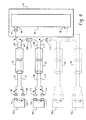
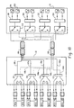
- FIG. 10 there is shown still another alternate embodiment of the present invention where only two single wavelengths of light 1,550 and 1,310 are used. It is noted that the four optical loops are substantially the same as discussed with respect to FIG. 6. However, instead of a single pair 42 of fibers 42a and 42b, the primary optical fiber bundle 186 is not made up of two fibers but is made up of four fibers 186a, 186b, 186c and 186d. Further, if there is to be redundancy of the primary fiber 186, it will be necessary to include a second four-fiber bundle 188 made up of fibers 188a, 188b, 188c and 188d.
- each of the fibers are connected to its own receiver and transmitter, such as receiver 206 and transmitter 208.
- switch 210 which operate similarly to the switches 186 and 187 with respect to FIG 7 above.
- the appropriate switch such as switch 210, would switch positions such that the information is now routed through the appropriate fiber of fiber bundle 188 and then back to its appropriate optical splitter 190.
Landscapes
- Engineering & Computer Science (AREA)
- Computer Networks & Wireless Communication (AREA)
- Signal Processing (AREA)
- Computing Systems (AREA)
- Physics & Mathematics (AREA)
- Electromagnetism (AREA)
- Optical Communication System (AREA)
- Use Of Switch Circuits For Exchanges And Methods Of Control Of Multiplex Exchanges (AREA)
- Small-Scale Networks (AREA)
Applications Claiming Priority (2)
| Application Number | Priority Date | Filing Date | Title |
|---|---|---|---|
| US09/876,439 US6898206B2 (en) | 2001-06-06 | 2001-06-06 | Wavelength division multiplexed (WDM) ring passive optical network (PON) with route protection for replacement of splitter based passive optical networks |
| US876439 | 2001-06-06 |
Publications (2)
| Publication Number | Publication Date |
|---|---|
| EP1265383A2 true EP1265383A2 (de) | 2002-12-11 |
| EP1265383A3 EP1265383A3 (de) | 2005-07-20 |
Family
ID=25367705
Family Applications (1)
| Application Number | Title | Priority Date | Filing Date |
|---|---|---|---|
| EP02253954A Withdrawn EP1265383A3 (de) | 2001-06-06 | 2002-06-06 | Optisches Übertragungssystem |
Country Status (2)
| Country | Link |
|---|---|
| US (3) | US6898206B2 (de) |
| EP (1) | EP1265383A3 (de) |
Cited By (1)
| Publication number | Priority date | Publication date | Assignee | Title |
|---|---|---|---|---|
| GB2418088A (en) * | 2004-09-10 | 2006-03-15 | Marconi Comm Ltd | Upgrading optical telecommunications networks |
Families Citing this family (35)
| Publication number | Priority date | Publication date | Assignee | Title |
|---|---|---|---|---|
| US6898206B2 (en) * | 2001-06-06 | 2005-05-24 | Advanced Fibre Access Corporation | Wavelength division multiplexed (WDM) ring passive optical network (PON) with route protection for replacement of splitter based passive optical networks |
| DE10133749B4 (de) * | 2001-07-11 | 2010-09-16 | Robert Bosch Gmbh | Netzwerkkomponente für ein optisches Netzwerk mit Notlauffunktion, insbesondere für ein optisches Netzwerk in Ringtopologie |
| US6853811B2 (en) * | 2001-09-12 | 2005-02-08 | Pts Corporation | Dual-wave optical shared protection ring |
| US7283739B2 (en) * | 2002-05-29 | 2007-10-16 | Fujitsu Limited | Multiple subnets in an optical ring network and method |
| US7283740B2 (en) * | 2002-05-29 | 2007-10-16 | Fujitsu Limited | Optical ring network with optical subnets and method |
| US7184663B2 (en) | 2002-05-29 | 2007-02-27 | Fujitsu Limited | Optical ring network with hub node and method |
| US7321729B2 (en) * | 2003-05-29 | 2008-01-22 | Fujitsu Limited | Optical ring network with selective signal regeneration and wavelength conversion |
| US8233800B2 (en) | 2003-06-26 | 2012-07-31 | Fujitsu Limited | Method and system for upgrading a fiber optics network |
| US20050089332A1 (en) * | 2003-10-03 | 2005-04-28 | Near Margalit | Long reach optical transmission over a single fiber |
| US20050089331A1 (en) * | 2003-10-03 | 2005-04-28 | Near Margalit | Assured connectivity fiber-optic communications link |
| US7483637B2 (en) * | 2003-11-26 | 2009-01-27 | Fujitsu Limited | Optical ring network with optical subnets and method |
| US20050175346A1 (en) * | 2004-02-10 | 2005-08-11 | Fujitsu Limited | Upgraded flexible open ring optical network and method |
| US7386235B2 (en) * | 2004-06-28 | 2008-06-10 | Lucent Technologies Inc. | Protocol and line-rate transparent WDM passive optical network |
| US20050286896A1 (en) * | 2004-06-29 | 2005-12-29 | Fujitsu Limited | Hybrid optical ring network |
| US7120360B2 (en) * | 2005-01-06 | 2006-10-10 | Fujitsu Limited | System and method for protecting traffic in a hubbed optical ring network |
| US7440701B2 (en) * | 2005-12-13 | 2008-10-21 | Broadway Networks, Ltd. | Fiber-to-the-premise optical communication system |
| US7805073B2 (en) * | 2006-04-28 | 2010-09-28 | Adc Telecommunications, Inc. | Systems and methods of optical path protection for distributed antenna systems |
| US7450848B2 (en) * | 2006-04-28 | 2008-11-11 | Broadway Networks, Ltd, | High-speed fiber-to-the-premise optical communication system |
| KR100762637B1 (ko) * | 2006-05-03 | 2007-10-01 | 삼성전자주식회사 | Tdd 방식의 무선 시스템 신호 전송을 위한 단일 파장양방향 rof 링크 장치 |
| US7317874B2 (en) * | 2006-06-02 | 2008-01-08 | Broadway Networks, Inc. | Adaptive optical transceiver for fiber access communications |
| US20080089699A1 (en) * | 2006-10-17 | 2008-04-17 | Wen Li | Methods for automatic tuning optical communication system |
| US20080279567A1 (en) * | 2007-05-09 | 2008-11-13 | Wen Huang | Asymmetric ethernet optical network system |
| CN101414932B (zh) * | 2007-10-15 | 2012-09-05 | 华为技术有限公司 | 长距离无源光网络系统中告警管理的方法、系统及装置 |
| US20090116845A1 (en) * | 2007-11-02 | 2009-05-07 | Wen Li | Tetintelligent optical transceiver capable of optical-layer management |
| DE102008005942A1 (de) * | 2008-01-24 | 2009-07-30 | Adva Ag Optical Networking | Verfahren zur Protection eines passiven optischen Übertragungsnetzes sowie passives optisches Übertragungsnetz mit entsprechendem Protection-Mechanismus |
| US7933518B2 (en) * | 2008-02-21 | 2011-04-26 | Finisar Corporation | Intelligent optical systems and methods for optical-layer management |
| US7974537B2 (en) * | 2008-06-05 | 2011-07-05 | Finisar Corporation | Intelligent pluggable transceiver stick capable of diagnostic monitoring and optical network management |
| US7957650B2 (en) * | 2008-06-26 | 2011-06-07 | Finisar Corporation | Pluggable optical network unit capable of status indication |
| US9246590B2 (en) * | 2009-02-22 | 2016-01-26 | Finisar Corporation | Smart optical transceiver having integrated optical dying gasp function |
| US8155516B2 (en) * | 2009-05-05 | 2012-04-10 | Alphion Corporation | Apparatus and method for ensuring continuity of fiber optic |
| US9641245B2 (en) | 2015-05-12 | 2017-05-02 | Saudi Arabian Oil Company | System, method, and apparatus for daisy chain network protection from node malfunction or power outage |
| US20170346553A1 (en) * | 2016-05-27 | 2017-11-30 | Corning Optical Communications LLC | Fiber optic assemblies for tapping live optical fibers in fiber optic networks employing wdm technology |
| EP3625904B1 (de) | 2017-05-17 | 2022-04-27 | Alcatel Submarine Networks | Verwendung von bandpassfiltern in überwachungssignalbahnen eines optischen transportsystems |
| EP3599726B1 (de) | 2018-07-25 | 2021-05-19 | Alcatel Submarine Networks | Überwachungsvorrichtung für ein optisches transportsystem |
| EP3696997B1 (de) | 2019-02-15 | 2022-06-15 | Alcatel Submarine Networks | Symmetrische optische überwachungsschaltung für einen bidirektionalen optischen verstärker |
Family Cites Families (19)
| Publication number | Priority date | Publication date | Assignee | Title |
|---|---|---|---|---|
| JPS61264835A (ja) * | 1985-05-17 | 1986-11-22 | Kawamura Denki Sangyo Kk | 光フアイバ−デ−タリンクシステム |
| NZ243764A (en) * | 1991-07-30 | 1995-05-26 | Alcatel Australia | Optical fibre network: mechanised subscriber loop testing |
| JP3158213B2 (ja) * | 1991-09-12 | 2001-04-23 | 富士通株式会社 | 並列伝送方法および装置 |
| US5784377A (en) * | 1993-03-09 | 1998-07-21 | Hubbell Incorporated | Integrated digital loop carrier system with virtual tributary mapper circuit |
| IT1265018B1 (it) * | 1993-08-10 | 1996-10-17 | Cselt Centro Studi Lab Telecom | Dispositivo per l'estrazione e il reinserimento di una portante ottica in reti di comunicazione ottica. |
| US5907417A (en) * | 1994-12-30 | 1999-05-25 | Lucent Technologies Inc. | Passive optical network with diagnostic loop-back |
| US5521734A (en) * | 1994-12-30 | 1996-05-28 | At&T Corp. | One-dimensional optical data arrays implemented within optical networks |
| JPH08205105A (ja) * | 1995-01-26 | 1996-08-09 | Hitachi Denshi Ltd | ディジタル信号伝送システム |
| US6088371A (en) * | 1995-04-05 | 2000-07-11 | Hitachi, Ltd. | Up-grading method for transmission apparatus |
| US5898828A (en) * | 1995-12-29 | 1999-04-27 | Emc Corporation | Reduction of power used by transceivers in a data transmission loop |
| US5903370A (en) * | 1996-06-28 | 1999-05-11 | Mci Communications Corporation | System for an optical domain |
| US6046833A (en) * | 1997-02-10 | 2000-04-04 | Optical Networks, Inc. | Method and apparatus for operation, protection, and restoration of heterogeneous optical communication networks |
| JPH11112430A (ja) * | 1997-10-08 | 1999-04-23 | Fujitsu Ltd | 光加入者ネットワークシステム及び光加入者ネットワークシステムにおける障害監視方法 |
| JPH11275028A (ja) * | 1998-03-20 | 1999-10-08 | Fujitsu Ltd | 光通信システム |
| US6307653B1 (en) * | 1999-03-24 | 2001-10-23 | Tellium, Inc | Optical matrix protection system |
| IL148462A0 (en) * | 1999-09-03 | 2002-09-12 | Oni Systems Corp | Optical power management in an optical network |
| DE69939017D1 (de) * | 1999-09-22 | 2008-08-14 | Lucent Technologies Inc | Optisches Netzwerk mit Leistungsteilern |
| US6977966B1 (en) * | 2000-11-28 | 2005-12-20 | Tellabs Bedford, Inc. | Bidirectional optical communications having quick data recovery without first establishing timing and phase lock |
| US6898206B2 (en) * | 2001-06-06 | 2005-05-24 | Advanced Fibre Access Corporation | Wavelength division multiplexed (WDM) ring passive optical network (PON) with route protection for replacement of splitter based passive optical networks |
-
2001
- 2001-06-06 US US09/876,439 patent/US6898206B2/en not_active Expired - Fee Related
-
2002
- 2002-06-06 EP EP02253954A patent/EP1265383A3/de not_active Withdrawn
-
2005
- 2005-03-23 US US11/088,070 patent/US7212541B2/en not_active Expired - Fee Related
-
2007
- 2007-04-30 US US11/741,813 patent/US20070201873A1/en not_active Abandoned
Cited By (1)
| Publication number | Priority date | Publication date | Assignee | Title |
|---|---|---|---|---|
| GB2418088A (en) * | 2004-09-10 | 2006-03-15 | Marconi Comm Ltd | Upgrading optical telecommunications networks |
Also Published As
| Publication number | Publication date |
|---|---|
| US7212541B2 (en) | 2007-05-01 |
| US6898206B2 (en) | 2005-05-24 |
| US20050163147A1 (en) | 2005-07-28 |
| US20020186439A1 (en) | 2002-12-12 |
| US20070201873A1 (en) | 2007-08-30 |
| EP1265383A3 (de) | 2005-07-20 |
Similar Documents
| Publication | Publication Date | Title |
|---|---|---|
| US6898206B2 (en) | Wavelength division multiplexed (WDM) ring passive optical network (PON) with route protection for replacement of splitter based passive optical networks | |
| US7433594B2 (en) | Node apparatus, optical wavelength division multiplexing network, and system switching method | |
| US6587235B1 (en) | Method and apparatus for capacity-efficient restoration in an optical communication system | |
| JP4256910B2 (ja) | 光ネットワーク及びプロテクションスイッチング方法 | |
| US6590681B1 (en) | Optical WDM network having an efficient use of wavelengths and a node therefor | |
| CA2308435C (en) | Telecommunications network having shared protect capacity architecture | |
| US7072580B2 (en) | Autoprotected optical communication ring network | |
| EP1876736A1 (de) | Passives optisches netzwerksystem auf der basis von wellenlängenschutz und schutz-backup-verfahren dafür | |
| US6687463B1 (en) | Communication system and method with optical banding | |
| USH2075H1 (en) | Restorable architectures for fiber-based broadband local access networks | |
| US6061482A (en) | Channel layered optical cross-connect restoration system | |
| US6728486B1 (en) | Communication system and method with optical management bus | |
| CN1305668A (zh) | Wdm信道的保护 | |
| WO2000076105A1 (en) | Communication system and method with optical banding and optical management bus | |
| KR20140073538A (ko) | 수동 광 네트워크에 연결된 노드들을 상호접속하기 위한 시스템 | |
| US6922530B1 (en) | Method and apparatus for optical channel switching in an optical add/drop multiplexer | |
| AU711802B2 (en) | Wavelength division multiplexed hybrid ring suitable for use in regional area networks | |
| WO1999018679A1 (en) | An optical network with protection path for failure recovery | |
| CN101005319B (zh) | 环形光传输网接入节点 | |
| KR100509819B1 (ko) | 링형 wdm pon 시스템 | |
| EP1206060A1 (de) | Multiplexer Struktur | |
| KR100967973B1 (ko) | 광순환기와 방향성광결합기를 구성한 다중화 및 역다중화장치 | |
| NZ233359A (en) | Optical communications system with wavelength-division multiplexing | |
| JP2002077049A (ja) | 波長多重伝送装置 |
Legal Events
| Date | Code | Title | Description |
|---|---|---|---|
| PUAI | Public reference made under article 153(3) epc to a published international application that has entered the european phase |
Free format text: ORIGINAL CODE: 0009012 |
|
| AK | Designated contracting states |
Kind code of ref document: A2 Designated state(s): AT BE CH CY DE DK ES FI FR GB GR IE IT LI LU MC NL PT SE TR |
|
| AX | Request for extension of the european patent |
Free format text: AL;LT;LV;MK;RO;SI |
|
| RIN1 | Information on inventor provided before grant (corrected) |
Inventor name: WAWRO, DEBRA D. Inventor name: VOLK, THOMAS Inventor name: TRICK, ULRICH Inventor name: ZUHDI, MUNEER Inventor name: BUABBUD, GEORGE H. |
|
| RAP1 | Party data changed (applicant data changed or rights of an application transferred) |
Owner name: MARCONI INTELLECTUAL PROPERTY (RINGFENCE) INC. |
|
| PUAL | Search report despatched |
Free format text: ORIGINAL CODE: 0009013 |
|
| STAA | Information on the status of an ep patent application or granted ep patent |
Free format text: STATUS: THE APPLICATION IS DEEMED TO BE WITHDRAWN |
|
| AK | Designated contracting states |
Kind code of ref document: A3 Designated state(s): AT BE CH CY DE DK ES FI FR GB GR IE IT LI LU MC NL PT SE TR |
|
| AX | Request for extension of the european patent |
Extension state: AL LT LV MK RO SI |
|
| RIC1 | Information provided on ipc code assigned before grant |
Ipc: 7H 04J 14/08 B Ipc: 7H 04J 14/02 B Ipc: 7H 04B 10/17 B Ipc: 7H 04B 10/20 A |
|
| 18D | Application deemed to be withdrawn |
Effective date: 20050101 |