EP1265420B1 - Verfahren zur Unterscheidung von Teilnehmer eines Kommunikationssystems, Kommunikationssystem und Kommunikationsgerät - Google Patents
Verfahren zur Unterscheidung von Teilnehmer eines Kommunikationssystems, Kommunikationssystem und Kommunikationsgerät Download PDFInfo
- Publication number
- EP1265420B1 EP1265420B1 EP02396076A EP02396076A EP1265420B1 EP 1265420 B1 EP1265420 B1 EP 1265420B1 EP 02396076 A EP02396076 A EP 02396076A EP 02396076 A EP02396076 A EP 02396076A EP 1265420 B1 EP1265420 B1 EP 1265420B1
- Authority
- EP
- European Patent Office
- Prior art keywords
- access network
- client
- communication system
- examined
- resolution
- Prior art date
- Legal status (The legal status is an assumption and is not a legal conclusion. Google has not performed a legal analysis and makes no representation as to the accuracy of the status listed.)
- Expired - Lifetime
Links
- 238000004891 communication Methods 0.000 title claims abstract description 104
- 238000000034 method Methods 0.000 title claims abstract description 50
- 230000005540 biological transmission Effects 0.000 claims description 23
- GWWNCLHJCFNTJA-UHFFFAOYSA-N nicandrenone-2 Natural products C12OC2C2(O)CC=CC(=O)C2(C)C(CCC23C)C1C3CCC2(O)C(C)C1OC(O)C2(C)OC2(C)C1 GWWNCLHJCFNTJA-UHFFFAOYSA-N 0.000 claims description 10
- 101100388299 Arabidopsis thaliana DTX54 gene Proteins 0.000 claims description 9
- 101100294133 Arabidopsis thaliana NIC2 gene Proteins 0.000 claims description 9
- 101100388291 Arabidopsis thaliana DTX49 gene Proteins 0.000 claims description 7
- 101100268840 Danio rerio chrna1 gene Proteins 0.000 claims description 7
- 101150065731 NIC1 gene Proteins 0.000 claims description 7
- PWHVEHULNLETOV-UHFFFAOYSA-N Nic-1 Natural products C12OC2C2(O)CC=CC(=O)C2(C)C(CCC2=C3)C1C2=CC=C3C(C)C1OC(O)C2(C)OC2(C)C1 PWHVEHULNLETOV-UHFFFAOYSA-N 0.000 claims description 7
- 239000010410 layer Substances 0.000 description 66
- 230000011664 signaling Effects 0.000 description 6
- 238000012546 transfer Methods 0.000 description 5
- 230000008878 coupling Effects 0.000 description 3
- 238000010168 coupling process Methods 0.000 description 3
- 238000005859 coupling reaction Methods 0.000 description 3
- 238000010586 diagram Methods 0.000 description 2
- 230000009365 direct transmission Effects 0.000 description 2
- 238000004821 distillation Methods 0.000 description 2
- 230000006870 function Effects 0.000 description 2
- 239000002346 layers by function Substances 0.000 description 2
- 230000008569 process Effects 0.000 description 2
- 230000004044 response Effects 0.000 description 2
- 230000006978 adaptation Effects 0.000 description 1
- 238000005516 engineering process Methods 0.000 description 1
- 230000007246 mechanism Effects 0.000 description 1
- 230000008520 organization Effects 0.000 description 1
- 238000012545 processing Methods 0.000 description 1
Images




Classifications
-
- H—ELECTRICITY
- H04—ELECTRIC COMMUNICATION TECHNIQUE
- H04L—TRANSMISSION OF DIGITAL INFORMATION, e.g. TELEGRAPHIC COMMUNICATION
- H04L69/00—Network arrangements, protocols or services independent of the application payload and not provided for in the other groups of this subclass
- H04L69/08—Protocols for interworking; Protocol conversion
- H04L69/085—Protocols for interworking; Protocol conversion specially adapted for interworking of IP-based networks with other networks
-
- H—ELECTRICITY
- H04—ELECTRIC COMMUNICATION TECHNIQUE
- H04L—TRANSMISSION OF DIGITAL INFORMATION, e.g. TELEGRAPHIC COMMUNICATION
- H04L69/00—Network arrangements, protocols or services independent of the application payload and not provided for in the other groups of this subclass
- H04L69/08—Protocols for interworking; Protocol conversion
-
- Y—GENERAL TAGGING OF NEW TECHNOLOGICAL DEVELOPMENTS; GENERAL TAGGING OF CROSS-SECTIONAL TECHNOLOGIES SPANNING OVER SEVERAL SECTIONS OF THE IPC; TECHNICAL SUBJECTS COVERED BY FORMER USPC CROSS-REFERENCE ART COLLECTIONS [XRACs] AND DIGESTS
- Y10—TECHNICAL SUBJECTS COVERED BY FORMER USPC
- Y10S—TECHNICAL SUBJECTS COVERED BY FORMER USPC CROSS-REFERENCE ART COLLECTIONS [XRACs] AND DIGESTS
- Y10S707/00—Data processing: database and file management or data structures
- Y10S707/99941—Database schema or data structure
- Y10S707/99943—Generating database or data structure, e.g. via user interface
Definitions
- the present invention relates to a method for distinguishing clients in a communication system comprising at least one wireless access network and at least one wired access network, said at least one wireless access network comprising means for connecting at least one wireless client in communication to said at least one wireless access network, said at least one wired access network comprising means for connecting at least one wired client in communication to said at least one wired access network, and said communication system comprising means for communicating between said at least one wireless access network and said at least one wired access network.
- the invention also relates to a communication system comprising at least one wireless access network and at least one wired access network, said at least one wireless access network comprising means for connecting at least one wireless client in communication to said at least one wireless access network, said at least one wired access network comprising means for connecting at least one wired client in communication to said at least one wired access network, and said communication system comprising means for communicating between said at least one wireless access network and said at least one wired access network.
- the invention further relates to a communication device comprising means for communicating with a communication system comprising at least one wireless access network and at least one wired access network, said at least one wireless access network comprising means for connecting at least one wireless client in communication to said at least one wireless access network, said at least one wired access network comprising means for connecting at least one wired client in communication to said at least one wired access network, and said communication system comprising means for communicating between said at least one wireless access network and said at least one wired access network.
- Such a communication system typically comprises at least one server and a number of clients.
- the clients can communicate with the server and other clients through different parts of the network.
- the wireless access network has one or more access point devices.
- the wireless clients can have access to the wireless access network through the access point devices.
- access point devices typically operate as link layer bridges between a wired access network such as Ethernet and the wireless access network such as WLAN.
- the wired access network and the wireless access network usually belong to a single IP sub-network. Every device (client, server, access point, etc.) connected to the network must have a unique IP address which is used when the device sends packets to the network and when unicast or multicast packets are sent via the network to the device. Normally such an IP sub-network has an address range in which addresses of all the devices of the sub-network belong.
- the invention is based on the idea that a resolution request message is transmitted from a requesting node to the network.
- a resolution reply message is transmitted to the requesting node only if the client belongs to the wired access network.
- a resolution reply message is transmitted to the requesting node only if the client belongs to the wireless access network.
- the method according to the present invention is primarily characterized in that the method comprises at least the following steps:
- a communication device is primarily characterized in that the communication device also comprises:
- the present invention shows remarkable advantages compared to solutions of prior art.
- clients belonging to the wireless access network can be distinguished from clients belonging to the wired access network without the need of performing manual configuration.
- inserting and removing of clients is easier.
- the node of the network can perform the checking which can be performed e.g. every time the node receives a packet which should be forwarded to a client, or a lifetime can be defined for the configuration information of a client wherein the node performs the check only if the lifetime has expired. This latter alternative can e.g. be used to reduce the amount of information to be transmitted in the communication system.
- Fig. 1 shows an example of a communication system 1 according to an advantageous embodiment of the present invention.
- the communication system 1 comprises at least one wireless access network 2 and at least one wired access network 3. It is obvious that there may exist more than one wireless access network and/or more than one wired access network in the communication system in which the present invention can be applied.
- the communication system 1 comprises access points AP1, AP2, AP3 which have transmitting and receiving means for providing communication with wireless clients WC1, WC2 and the wireless access network 2.
- the wireless client WC1, WC2 can, for example, be a wireless terminal having data processing means, such as a laptop PC, and wireless communication means, such as a radio modem.
- Some wireless access networks may comprise one or more access point controllers separate from the access points. The function of the access point controllers is to control the operation of the access points. The communication between the wireless clients and the rest of the communication system is routed via the access point controller(s). However, in Fig. 1 all the access points AP1, AP2, AP3 and (possible) access point controllers are shown as single units.
- the access points AP1, AP2, AP3 are directly connected to the wired network in the communication system 1 of Fig. 1, wherein all the access points AP1, AP2, AP3 can directly communicate with other access points and other devices connected to the wired access network 3.
- a radio connection is arranged between the access point AP1, AP2 and the wireless clients WC1, WC2 for transmitting e.g. signals required for setting up a connection and, during the connection, information, such as data packets of an Internet application.
- the wired access network 3 comprises one or more servers S, one or more routers R and it may also comprise one or more wired clients C.
- the server S controls the operation of the wired access network 3, and it can communicate with other devices connected to the wired access network 3.
- the router R is implemented in such communication systems 1 in which communication with other networks e.g. Internet is necessary.
- the router R routes data packets from the wired and wireless access network to other networks and, respectively, receives packets from other networks and retransmits the received packets to the intended receiver, or to another router.
- a TCP/IP protocol stack is generally used, which can be divided into five functional layers. These five layers are, listed from bottom to top: the physical layer (Layer 1), the link layer (Layer 2), the network layer (Layer 3), the transport layer (Layer 4), and the application layer (Layer 5). All the nodes of the Internet data network contain at least the first three layers. Of these nodes, routers, which are primarily responsible for the couplings of the data network, do not need the transport and application layers. However, hosts, between which the actual data transmission connection is set up, contain all the said five layers. Even though all the upper level layers use the services of the underlying layer for data transmission, logically the corresponding layers of the hosts communicate with each other by using the protocol typical for the layer.
- the actual data transmission is conducted in the physical layer by using a data transmission means, such as a wireless radio network or landline cabling.
- the link layer attends to solutions required by different network technologies, wherein the upper level layers do not have to know how the data transmission network used at a given time is constructed.
- the link layer processes different addressing and frame modes and is responsible for the data transmission between two terminals in the same communication network.
- the task of the network layer is to route packets between terminals in the communication network.
- the network layer provides the coupling between different data networks, wherein the upper level layers do not have to know about the structure of the data network.
- protocols IP Internet Protocol
- ICMP Internet Control Message Protocol
- IGMP Internet Group Management Protocol
- the transport layer provides a generic end-to-end data transmission connection for the application layer.
- the application layer uses for instance a TCP protocol (Transmission Control Protocol) and a UDP protocol (User Datagram Protocol).
- TCP Transmission Control Protocol
- UDP User Datagram Protocol
- the application layer protocols operate above the transport layer and provide application-specific services, such as file transfer services or access network remote login services.
- the application layer protocols operate above the transport layer and provide application-specific services, such as file transfer services or access network remote login services.
- applications running on the application layer in the wireless client WC1 and in the wired host S communicate with each other via the access point AP1.
- HTTP protocol HyperText Transfer Protocol
- HTTP protocol is generally used in the Internet data network for loading and presenting the data contained in so-called home pages in the display device of a computer.
- Other application layer protocols are, for example, Telnet, the file transfer protocol FTP and the simple mail transfer protocol SMTP.
- each client or host has its own identifying IP address.
- the IP address is in the Internet protocol version IPv4 a 32 bit, i.e. 4 byte number which is split into an organization-specific network address and a network-specific device address.
- IPv6 the length of the address fields is increased to 128 bits, which, in practice, means that it is possible to allocate an individual address for all the devices which are connected to the Internet data network.
- An Internet host connected to the Internet data network via a access network 2, 3 has either a permanently specified Internet address or the address is a dynamic address established by the access network server (for example by using dynamic host configuration protocol DHCP).
- the host has to request for an Internet address from the Internet service provider, to which the Internet host is registered. This is conducted, for example, according to a point-to-point protocol PPP.
- PPP point-to-point protocol
- the Internet protocol IP specifies the data transmission in packets ("Datagrams").
- Datagrams data transmission in packets
- the first step is to examine whether the packet is intended precisely for the router or client in question. If the packet is intended precisely for this router or client, the packet is transferred from the network layer to the upper layer in this node. If the packet is intended to another node, a so-called routing algorithm is executed in the network layer for concluding how the packet should be processed. First, it is examined whether the packet is intended for another node in the same network. If this is the case, the node can transmit the packet to the destination address by using the mechanisms of the link layer. Thus, the IP address of the network layer level is connected to the corresponding link layer address by using the so-called address resolution protocol ARP. In this node, the packet is also framed into a packet corresponding to the link layer and transmitted further.
- ARP address resolution protocol
- the routing algorithm runs through a routing table in order to find out to which address the packet should be transmitted.
- the routing table typically contains a so-called default address, to which all such packets are transmitted whose routing address cannot be found in the routing table.
- the transmission of IP packets between different coupled data networks on the network layer level is conducted on the basis of IP addresses.
- the devices connected to the Internet data network also have a so-called link layer address, which is also called a device address.
- link layer address which is also called a device address.
- terminals use link layer services in packet transmission with terminals connected to the same data network, the terminals need the address resolution protocol ARP for connecting the IP addresses to the corresponding link layer addresses.
- the reverse address resolution protocol RARP connects the link layer addresses to the corresponding IP addresses.
- the function of the address resolution protocol ARP depends on the structure of the data transmission connection used at a given time.
- the address resolution program typically uses four different messages: an ARP request, an ARP reply, an RARP request, and an RARP reply.
- a requesting node such as some of the access points AP1, AP2, AP3, needs to find out whether a target node resides on the wireless access network 2 or on the wired access network 3, a resolution request message is formed in the requesting node and transmitted to the wired access network 3. If the requesting node is an access point AP1, AP2, AP3, it transmits the message over the wired network interface NIC2 of the access point AP1, AP2, AP3 (Fig. 7) to the wired access network 3. The requesting node also starts a controlling timer T (Fig. 7).
- the resolution request message can be transmitted as a unicast message addressed directly to the link-layer address of the target node wherein the message comprises the link-layer address of the target node.
- the target node is one of the access points AP1, AP2, AP3 of the wireless access network 2, or one of the wired nodes S, R of the wired access network 3.
- the resolution request message may also be transmitted as a multicast message wherein it comprises a special multicast address. It is also possible to use broadcast transmission wherein the resolution request message is marked as a broadcast message wherein all nodes of the wired access network 3 receive and process the message.
- the target node AP1, AP2, AP3, S, R receives the resolution request message which is either addressed to it or is a broadcast message
- the target node examines the contents of the message.
- the message comprises identification information of the target node.
- the identification information is usually the address of the target node.
- the target node S, R examines whether the identification information of the message equals the identification information of the target node, and if it does the target node will form a resolution reply message.
- the target node will then transmit the resolution reply message preferably as a unicast message to the requesting node.
- the steps of the method of the present invention are advantageously implemented mainly on the link-layer level procedures of the protocol stack of the nodes.
- the lower level layers of the protocol stack perform necessary steps to forward the messages between physical layer and the link-layer of the protocol stack.
- the target node cannot support the resolution request message according to the invention.
- the requesting node When the requesting node receives the resolution reply message, it examines the address of the sender or some other information of the message to find out to which resolution request message the reply was transmitted. The requesting node can then determine that the target node in question is connected to the wired access network 3. The requesting node may store the resolution information of the target node into memory means MEM (e.g. cache) so that it is not necessary to send the resolution request message every time the requesting node needs to find out on which access network 2, 3 the target node is situated. The requesting node may also define a lifetime for the resolution information.
- MEM e.g. cache
- the requesting node first examines if the lifetime of the resolution information is expired. If it is not yet expired the requesting node uses the stored resolution information. Otherwise, the requesting node sends the resolution request message and waits for an answer.
- the target node does not receive the resolution request message. Neither does any proxy of the wired access network 3 have information of the target node. In that kind of situation the resolution reply message is not transmitted in the wired access network 3, wherein the requesting node will not receive the resolution reply message as is shown in Fig. 3.
- the requesting node may schedule a retransmission timer for the resolution request so that the resolution request message is retransmitted a couple of times if no response has been received.
- the requesting node determines that the target node in question does not belong to the wired access network 3, if the requesting node does not receive a resolution reply message within a certain time period.
- the requesting node can perform the above described checking procedure for more than one target node and save the resolution information of each checked target node.
- RARP Reverse Address Resolution Protocol
- the requesting node can send a RARP request message as the resolution request message in order to resolve whether a target node is on the wired access network.
- Target nodes which are on the wired access network 3 can then reply with a RARP reply message, or if the replying node is a proxy on behalf of the target node, a proxy RARP reply message can be used. If RARP is used, the access points must not forward the resolution request messages over the wireless access network.
- a requesting node such as some of the wired nodes S, R or access points AP1, AP2, AP3 needs to find out whether a target node resides on the wireless access network 2 or on the wired access network 3, a resolution request message is formed e.g. in the link-layer of the requesting node. Then, the requesting node transmits the resolution request message to the wired access network 3.
- the requesting node is an access point AP1, AP2, AP3, it transmits the message over the wired network interface NIC2 of the access point AP1, AP2, AP3 to the wired access network 3.
- This resolution request message can be transmitted as a unicast message addressed directly to the link-layer address of the target node wherein the message comprises the link-layer address of the target node.
- the target node is one of the access points AP1, AP2, AP3 of the wireless access network 2, or one of the wired nodes S, R of the wired access network 3.
- the resolution request message may also be transmitted as a multicast message wherein it comprises a special multicast address. It is also possible to use broadcast transmission wherein the resolution request message is marked as a broadcast message.
- the access points AP1, AP2, AP3 of the wireless access network need to maintain information of wireless clients which are associated with the access point AP1, AP2, AP3.
- an access point AP1, AP2, AP3 receives the resolution request message which is either addressed to it or is a broadcast message, the message is transferred to the link-layer of the protocol stack of the access point AP1, AP2, AP3. Then the link-layer level procedures of the access point AP1, AP2, AP3 examine the contents of the message.
- the message comprises identification information of the target node. In the access point AP1, AP2, AP3 it is examined if the message has information of the target node.
- the access point AP1, AP2, AP3 it is examined which wireless clients are connected with the access point AP1, AP2, AP3. If the identification information of the message indicates that the target node is a wireless client connected to the access point, a resolution reply message is formed in the access point AP1, AP2, AP3 and transmitted to the requesting node over the wired network interface of the access point.
- the requesting node When the requesting node receives the resolution reply message, message is transferred to the link-layer of the protocol stack of the requesting node. Then the link-layer level procedures of the requesting node examine the address of the sender or some other information of the message to find out to which resolution request message the reply was transmitted. The requesting node can then determine that the target node in question is connected to the wireless access network 2. The requesting node may save the resolution information of the target node so that it is not necessary to send the resolution request message every time the requesting node needs to find out on which access network 2, 3 the target node is situated. The requesting node may also define a lifetime for the resolution information.
- the requesting node first examines if the lifetime of the resolution information is expired. If it has not yet expired the requesting node uses the stored resolution information. Otherwise, the requesting node sends the resolution request message and waits for an answer.
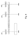
- the target node is not in the wireless access network 2, no access point has identification information similar to the identification information of the resolution request message. Therefore the resolution reply message is not formed and transmitted in the wired access network 3 and the requesting node will not receive the resolution reply message as is shown in Fig. 5.
- the requesting node may schedule a retransmission timer for the resolution request so that the resolution request message is retransmitted a couple of times if no response has been received.
- the requesting node determines that the target node in question does not belong to the wireless access network 2, if the requesting node does not receive a resolution reply message within a certain time period.
- the requesting node can perform the above described check for more than one target node and save the resolution information of each checked target node.
- the requesting node can use the resolution information for different purposes. For example, there may exist situations in which transmission of information should be restricted only to devices of the wired access network 3.
- the node When a node of the wired access network receives a packet which should be forwarded to a client, the node first examines the resolution information of the client. If the resolution information indicates that the client is connected to a part of the network where the packet is not allowed to be forwarded, the node will not forward the packet to the client. Otherwise the packet will be forwarded normally.
- the direct transmission between clients of the wireless access network can be prevented by examining at the access point the resolution information prior to packets from one client are forwarded to another client.
- the resolution reply message is transmitted independent of whether the target node is a wireless client or a wired client. This is possible, for example, in a communication system 1 in which the access point AP1, AP2, AP3 transmits the resolution reply message if the target node is a wireless client, and the target node or proxy transmits the resolution reply message if the target node is a wired client. Therefore the requesting device can determine from the sender of the resolution reply message whether the target node is a wireless client or a wired client.
- the appended Fig. 7 presents in a reduced manner the features of the access point AP1, AP2, AP3 which are meaningful when implementing the present invention.
- the hardware part includes, for instance, a microprocessor ⁇ P, memory means MEM, a connection logic I/O, and retransmission timer T.
- the network interface architecture comprises a wireless network interface NIC1 and a wired network interface NIC 2, by means of which the actual physical data transmission connection is established.
- the practical implementation of these network interfaces depends, for instance, on the type of the network interface in question.
- a network interface card intended for a wireless access network comprises a radio modem, or the like, whereby it is possible to set up a wireless data transmission connection to the radio modem of the access network.
- the network interfaces NIC1, NIC2 constitute said physical layer and can also contain features of the link layer.
Landscapes
- Engineering & Computer Science (AREA)
- Computer Security & Cryptography (AREA)
- Computer Networks & Wireless Communication (AREA)
- Signal Processing (AREA)
- Mobile Radio Communication Systems (AREA)
- Small-Scale Networks (AREA)
- Communication Control (AREA)
Claims (37)
- Verfahren zum Unterscheiden von Clients (WC1, WC2) in einem Kommunikationssystem (1), welches wenigstens ein drahtloses Zugangsnetz (2) und wenigstens ein drahtgebundenes Zugangsnetz (3) umfasst, wobei das wenigstens eine drahtlose Zugangsnetz (2) Mittel zum Verbinden wenigstens eines drahtlosen Clients (WC1, WC2) in Kommunikation mit dem wenigstens einen drahtlosen Zugangsnetz (2) umfasst, das wenigstens eine drahtgebundene Zugangsnetz (3) Mittel zum Verbinden wenigstens eines drahtgebundenen Clients (C) in Kommunikation mit dem wenigstens einen drahtgebundenen Zugangsnetz (3) umfasst, und das Kommunikationssystem (1) Mittel zum Kommunizieren zwischen dem wenigstens einen drahtlosen Zugangsnetz (2) und dem wenigstens einen drahtgebundenen Zugangsnetz (3) umfasst, dadurch gekennzeichnet, dass das Verfahren wenigstens die folgenden Schritte umfasst:- einen Sendeschritt zum Senden einer Auflösungsanfragenachricht, welche einen zu überprüfenden Client (WC1, WC2, C) angibt, von einem anfragenden Knoten (AP1, AP2, AP3, S, R) an das Kommunikationssystem (1);- einen Empfangsschritt zum Empfangen der Auflösungsanfragenachricht in wenigstens einem anderen Knoten (AP1, AP2, AP3, S, R) des Kommunikationssystems (1), und- einen Entscheidungsschritt zum Folgern auf der Basis einer Auflösungsantwortnachricht, ob der zu überprüfende Client (WC1, WC2, C) mit dem drahtlosen Zugangsnetz (2) oder dem drahtgebundenen Zugangsnetz (3) verbunden ist.
- Verfahren nach Anspruch 1, wobei das Verfahren ferner einen Schritt zum Überprüfen der Auflösungsanfragenachricht in dem wenigstens einen anderen Knoten (AP1, AP2, AP3, S, R) des Kommunikationssystems (1) und zum Entscheiden, ob die Auflösungsantwortnachricht von dem wenigstens einen anderen Knoten (AP1, AP2, AP3, S, R) des Kommunikationssystems (1) an das Kommunikationssystem (1) zu senden ist.
- Verfahren nach Anspruch 2, wobei im Entscheidungsschritt eine Überprüfung dessen erfolgt, ob die Auflösungsantwortnachricht von wenigstens einem anderen Knoten (AP1, AP2, AP3, S, R) des Kommunikationssystems (1) gesendet wird, wobei die Entscheidung darüber, ob der zu überprüfende Client (WC1, WC2, C) mit dem drahtlosen Zugangsnetz (2) oder mit dem drahtgebundenen Zugangsnetz (3) verbunden ist, auf der Basis dessen, ob die Auflösungsantwortnachricht in dem anfragenden Knoten (AP1, AP2, AP3, S, R) empfangen wird, getroffen wird.
- Verfahren nach Anspruch 2, wobei die Auflösungsantwortnachricht von wenigstens einem anderen Knoten (AP1, AP2, AP3, S, R) des Kommunikationssystems (1) gesendet wird, wobei die Entscheidung darüber, ob der zu überprüfende Client (WC1, WC2, C) mit dem drahtlosen Zugangsnetz (2) oder mit dem drahtgebundenen Zugangsnetz (3) verbunden ist, auf der Basis dessen getroffen wird, ob die Auflösungsantwortnachricht von einem Knoten (AP1, AP2, AP3), der dem drahtlosen Zugangsnetz (2) angehört, oder von einem Knoten (S, R), der dem drahtgebundenen Zugangsnetz (3) angehört, gesendet wird.
- Verfahren nach Anspruch 1, wobei die Auflösungsanfragenachricht eine Adresse des zu überprüfenden Clients (WC1, WC2, C) angibt.
- Verfahren nach Anspruch 5, wobei die Adresse eine Sicherungsschichtadresse des zu überprüfenden Clients (WC1, WC2, C) ist.
- Verfahren nach Anspruch 1, wobei eine Steuerzeit definiert wird und, wenn die Auflösungsantwortnachricht nicht während der Steuerzeit empfangen wird, die Entscheidung darüber, ob der zu überprüfende Client (WC1, WC2, C) mit dem drahtlosen Zugangsnetz (2) oder mit dem drahtgebundenen Zugangsnetz (3) verbunden ist, getroffen wird.
- Verfahren nach Anspruch 1, wobei eine Steuerzeit definiert wird, eine maximale Wiederholungszählung definiert wird und, wenn die Auflösungsantwortnachricht nicht während der Steuerzeit empfangen wird, die Auflösungsanfragenachricht wieder gesendet wird, wenn die Anzahl von Wiederholungssendungen kleiner als die maximale Wiederholungszählung ist.
- Verfahren nach Anspruch 1, wobei die Auflösungsantwortnachricht gesendet wird, wenn der zu überprüfende Client (WC1, WC2, C) mit dem wenigstens einen drahtgebundenen Zugangsnetz (3) verbunden ist.
- Verfahren nach Anspruch 9, wobei die Auflösungsantwortnachricht von dem zu überprüfenden Client (WC1, WC2, C) gesendet wird.
- Verfahren nach Anspruch 9, wobei das drahtgebundene Zugangsnetz (3) wenigstens einen Proxy aufweist und die Auflösungsanfragenachricht in dem wenigstens einen Proxy empfangen wird, wobei, wenn der zu überprüfende Client (WC1, WC2, C) mit dem wenigstens einen drahtgebundenen Zugangsnetz (3) verbunden ist, die Auflösungsantwortnachricht von dem Proxy gesendet wird.
- Verfahren nach Anspruch 1, wobei die Auflösungsantwortnachricht gesendet wird, wenn der zu überprüfende Client (WC1, WC2, C) mit dem wenigstens einen drahtlosen Zugangsnetz (2) verbunden ist.
- Verfahren nach Anspruch 12, wobei das drahtgebundene Zugangsnetz (3) wenigstens einen Zugangspunkt aufweist und die Auflösungsanfragenachricht in dem wenigstens einen Zugangspunkt empfangen wird, wobei, wenn der zu überprüfende Client (WC1, WC2, C) mit dem wenigstens einen drahtlosen Zugangsnetz (2) verbunden ist, die Auflösungsantwortnachricht von dem Zugangspunkt gesendet wird.
- Verfahren nach Anspruch 1, wobei das drahtgebundene Zugangsnetz (3) wenigstens einen Zugangspunkt aufweist, wobei, wenn der zu überprüfende Client (WC1, WC2, C) mit dem wenigstens einen drahtgebundenen Zugangsnetz (3) verbunden ist, die Auflösungsantwortnachricht von dem zu überprüfenden Client (WC1, WC2, C) gesendet wird, und, wenn der zu überprüfende Client (WC1, WC2, C) mit dem wenigstens einen drahtlosen Zugangsnetz (2) verbunden ist, die Auflösungsantwortnachricht von dem Zugangspunkt gesendet wird.
- Verfahren nach Anspruch 1, wobei das drahtgebundene Zugangsnetz (3) wenigstens einen Proxy aufweist und das drahtgebundene Zugangsnetz (3) wenigstens einen Zugangpunkt (S, R) aufweist, wobei, wenn der zu überprüfende Client (WC1, WC2, C) mit dem wenigstens einen drahtgebundenen Zugangsnetz (3) verbunden ist, die Auflösungsantwortnachricht von dem Proxy gesendet wird, und, wenn der zu überprüfende Client (WC1, WC2, C) mit dem wenigstens einen drahtlosen Zugangsnetz (2) verbunden ist, die Auflösungsantwortnachricht von dem Zugangspunkt (S, R) gesendet wird.
- Verfahren nach Anspruch 1, in welchem das umgekehrte Adressauflösungsprotokoll (RARP) verwendet wird, wobei eine RARP-Anfragenachricht als die Auflösungsanfragenachricht verwendet wird.
- Verfahren nach Anspruch 16, wobei eine RARP-Antwortnachricht als die Auflösungsantwortnachricht verwendet wird, wenn die Auflösungsantwortnachricht von dem zu überprüfenden Client (MC1, MC2, C) gesendet wird, und es wird eine Proxy-RARP-Antwortnachricht als die Auflösungsantwortnachricht verwendet, wenn die Auflösungsantwortnachricht von einem anderen Knoten (AP1, AP2, AP3, S, R) des Kommunikationssystems (1) als dem zu überprüfenden Client (WC1, WC2, C) gesendet wird.
- Verfahren nach Anspruch 1, wobei Informationen darüber gespeichert werden, ob ein zu überprüfender Client (WC1, WC2, C) mit dem drahtlosen Zugangsnetz (2) oder dem drahtgebundenen Zugangsnetz (3) verbunden ist.
- Verfahren nach Anspruch 18, wobei die Informationen im anfragenden Knoten (AP1, AP2, AP3, S, R) gespeichert werden.
- Kommunikationssystem (1), umfassend wenigstens ein drahtloses Zugangsnetz (2) und wenigstens ein drahtgebundenes Zugangsnetz (3), wobei das wenigstens eine drahtlose Zugangsnetz (2) Mittel zum Verbinden wenigstens eines drahtlosen Clients (WC1, WC2) in Kommunikation mit dem wenigstens einen drahtlosen Zugangsnetz (2) umfasst, das wenigstens eine drahtgebundene Zugangsnetz (3) Mittel (S, 4) zum Verbinden wenigstens eines drahtgebundenen Clients (C) in Kommunikation mit dem wenigstens einen drahtgebundenen Zugangsnetz (3) umfasst, und das Kommunikationssystem (1) Mittel (AP1, AP2, AP3) zum Kommunizieren zwischen dem wenigstens einen drahtlosen Zugangsnetz (2) und dem wenigstens einen drahtgebundenen Zugangsnetz (3) umfasst, dadurch gekennzeichnet, dass das Kommunikationsnetz (1) auch umfasst:- Mittel (NIC1, NIC2) zum Senden einer Auflösungsanfragenachricht, die einen zu überprüfenden Client (WC1, WC2, C) angibt, von einem anfragenden Knoten (AP1, AP2, AP3, S, R) an das Kommunikationssystem (1),- Mittel (NIC1, NIC2) zum Empfangen der Auflösungsanfragenachricht in wenigstens einem anderen Knoten (AP1, AP2, AP3, S, R) des Kommunikationssystems (1), und- Mittel (µP, I/O) zum Entscheiden auf der Basis einer Auflösungsantwortnachricht, ob der zu überprüfende Client (WC1, WC2) mit dem drahtlosen Zugangsnetz (2) oder dem drahtgebundenen Zugangsnetz (3) verbunden ist.
- Kommunikationssystem (1) nach Anspruch 20, umfassend Mittel (µP) zum Überprüfen der Auflösungsanfragenachricht in dem wenigstens einen anderen Knoten (AP1, AP2, AP3, S, R) des Kommunikationssystems (1) und zum Entscheiden, ob die Auflösungsantwortnachricht von dem wenigstens einen anderen Knoten (AP1, AP2, AP3, S, R) des Kommunikationssystems (1) an das Kommunikationssystem (1) zu senden ist.
- Kommunikationssystem (1) nach Anspruch 21, umfassend Mittel (µP) zum Überprüfen, ob die Auflösungsanfragenachricht von dem wenigstens einen anderen Knoten (AP1, AP2, AP3, S, R) des Kommunikationssystems (1) gesendet wurde, wobei die Mittel (µP, I/O) zum Entscheiden, ob der zu überprüfende Client (WC1, WC2, C) mit dem drahtlosen Zugangsnetz (2) oder mit dem drahtgebundenen Zugangsnetz (3) verbunden ist, Mittel (µP) zum Treffen der Entscheidung auf der Basis dessen, ob die Auflösungsantwortnachricht in dem anfragenden Knoten (AP1, AP2, AP3, S, R) empfangen wird, umfassen.
- Kommunikationssystem (1) nach Anspruch 21, wobei die Mittel (µP, I/O) zum Entscheiden, ob der zu überprüfende Client (WC1, WC2, C) mit dem drahtlosen Zugangsnetz (2) oder mit dem drahtgebundenen Zugangsnetz (3) verbunden ist, Mittel (µP) zum Überprüfen, ob die Auflösungsantwortnachricht von einem Knoten (AP1, AP2, AP3, S, R), der dem drahtlosen Zugangsnetz (2) angehört, oder von einem Knoten gesendet wurde, der dem drahtgebundenen Zugangsnetz (3) angehört, umfassen.
- Kommunikationssystem (1) nach Anspruch 20, wobei die Auflösungsanfragenachricht eine Adresse des zu überprüfenden Clients (WC1, WC2, C) angibt.
- Kommunikationssystem (1) nach Anspruch 24, wobei die Adresse eine Sicherungsschichtadresse des zu überprüfenden Clients (WC1, WC2, C) ist.
- Kommunikationssystem (1) nach Anspruch 20, wobei es ferner einen Steuerzeitgeber (T) zum Definieren einer Steuerzeit umfasst, wobei Mittel (µP) zum Entscheiden, ob der zu überprüfende Client (WC1, WC2, C) mit dem drahtlosen Zugangsnetz (2) oder mit dem drahtgebundenen Zugangsnetz (3) verbunden ist, Mittel (µP) zum Überprüfen der Steuerzeitgebers umfassen.
- Kommunikationssystem (1) nach Anspruch 20, wobei es ferner einen Steuerzeitgeber (T) zum Definieren einer Steuerzeit, Mittel (µP) zum Definieren einer maximalen Wiederholungszählung und Mittel (NIC1, NIC2) zum Wiedersenden der Auflösungsanfragenachricht, wenn die Auflösungsantwortnachricht nicht während der Steuerzeit empfangen wird und wenn die Anzahl von Widerholungssendungen kleiner als die maximale Wiederholungszählung ist, umfasst.
- Kommunikationssystem (1) nach Anspruch 20, wobei die Auflösungsantwortnachricht gesendet wird, wenn der zu überprüfende Client (WC1, WC2, C) mit dem wenigstens einen drahtgebundenen Zugangsnetz (3) verbunden ist.
- Kommunikationssystem (1) nach Anspruch 28, wobei der Client (WC1, WC2, C) Mittel zum Senden der Auflösungsantwortnachricht umfasst.
- Kommunikationssystem (1) nach Anspruch 28, wobei das drahtgebundene Zugangsnetz (3) wenigstens einen Proxy aufweist, der Mittel zum Empfangen der Auflösungsanfragenachricht und Mittel zum Senden der Auflösungsantwortnachricht, wenn der zu überprüfende Client (WC1, WC2, C) mit dem wenigstens einen drahtgebundenen Zugangsnetz (3) verbunden ist, umfasst.
- Kommunikationssystem (1) nach Anspruch 20, wobei die Auflösungsantwortnachricht gesendet wird, wenn der zu überprüfende Client (WC1, WC2, C) mit dem wenigstens einen drahtlosen Zugangsnetz (2) verbunden ist.
- Kommunikationssystem (1) nach Anspruch 21, wobei das drahtgebundene Zugangsnetz (3) wenigstens einen Zugangspunkt (AP1, AP2, AP3) aufweist, der Mittel (NIC1, NIC2) zum Empfangen der Auflösungsanfragenachricht und Mittel (NIC1, NIC2) zum Senden Auflösungsantwortnachricht, wenn der zu überprüfende Client (WC1, WC2, C) mit dem wenigstens einen drahtlosen Zugangsnetz (2) verbunden ist, umfasst.
- Kommunikationssystem (1) nach Anspruch 2, wobei die Mittel (AP1, AP2, AP3) zum Kommunizieren zwischen dem wenigstens einen drahtlosen Zugangsnetz (2) und dem wenigstens einen drahtgebundenen Zugangsnetz (3) wenigstens einen Zugangspunkt (AP1, AP2, AP3) umfassen, wobei der anfragende Knoten (AP1, AP2, AP3, S, R) der Zugangspunkt (AP1, AP2, AP3) ist.
- Kommunikationsgerät (AP1, AP2, AP3), umfassend Mittel zum Kommunizieren mit einem Kommunikationssystem (1), welches wenigstens ein drahtloses Zugangsnetz (2) und wenigstens ein drahtgebundenes Zugangnetz (3) umfasst, wobei das wenigstens eine drahtlose Zugangsnetz (2) Mittel zum Verbinden wenigstens eines drahtlosen Clients (WC1, WC2) in Kommunikation mit dem wenigstens einen drahtlosen Zugangsnetz (2) umfasst, das wenigstens eine drahtgebundene Zugangsnetz (3) Mittel (S, R) zum Verbinden wenigstens eines drahtgebundenen Clients (C) in Kommunikation mit dem wenigstens einen drahtgebundenen Zugangsnetz (3) umfasst, und das Kommunikationssystem (1) Mittel (AP1, AP2, AP3) zum Kommunizieren zwischen dem wenigstens einen drahtlosen Zugangsnetz (2) und dem wenigstens einen drahtgebundenen Zugangsnetz (3) umfasst, dadurch gekennzeichnet, dass das Kommunikationsgerät (AP1, AP2, AP3) auch umfasst:- Mittel (NIC1, NIC2) zum Senden einer Auflösungsanfragenachricht, die einen zu überprüfenden Client (WC1, WC2, C) angibt, von einem anfragenden Knoten (AP1, AP2, AP3, S, R) an das Kommunikationssystem (1),- Mittel (µP, I/O) zum Entscheiden auf der Basis einer Auflösungsantwortnachricht, ob der zu überprüfende Client (WC1, WC2) mit dem drahtlosen Zugangsnetz (2) oder dem drahtgebundenen Zugangsnetz (3) verbunden ist.
- Kommunikationsgerät (AP1, AP2, AP3) nach Anspruch 34, umfassend Mittel (µP) zum Überprüfen, ob die Auflösungsanfragenachricht von dem wenigstens einen anderen Knoten (AP1, AP2, AP3, S, R) des Kommunikationssystems (1) gesendet wurde, wobei die Mittel (µP, I/0) zum Entscheiden, ob der zu überprüfende Client (WC1, WC2, C) mit dem drahtlosen Zugangsnetz (2) oder mit dem drahtgebundenen Zugangsnetz (3) verbunden ist, Mittel (µP) zum Treffen der Entscheidung auf der Basis dessen, ob die Auflösungsantwortnachricht in dem anfragenden Knoten (AP1, AP2, AP3, S, R) empfangen wird, umfassen.
- Kommunikationsgerät (AP1, AP2, AP3) nach Anspruch 34, wobei die Mittel (µP, I/O) zum Entscheiden, ob der zu überprüfende Client (WC1, WC2, C) mit dem drahtlosen Zugangsnetz (2) oder mit dem drahtgebundenen Zugangsnetz (3) verbunden ist, Mittel (µP) zum Überprüfen, ob die Auflösungsantwortnachricht von einem Knoten, der dem drahtlosen Zugangsnetz (2) angehört, oder von einem Knoten gesendet wurde, der dem drahtgebundenen Zugangsnetz (3) angehört, umfassen.
- Kommunikationsgerät (AP1, AP2, AP3) nach Anspruch 34, umfassend Mittel (MEM) zum Speichern von Informationen darüber, ob der zu überprüfende Client (WC1, WC2, C) mit dem drahtlosen Zugangsnetz (2) oder mit dem drahtgebundenen Zugangsnetz (3) verbunden ist.
Applications Claiming Priority (2)
| Application Number | Priority Date | Filing Date | Title |
|---|---|---|---|
| US09/876,480 US7085808B2 (en) | 2001-06-07 | 2001-06-07 | Method for distinguishing clients in a communication system, a communication system; and a communication device |
| US876480 | 2001-06-07 |
Publications (3)
| Publication Number | Publication Date |
|---|---|
| EP1265420A2 EP1265420A2 (de) | 2002-12-11 |
| EP1265420A3 EP1265420A3 (de) | 2003-07-02 |
| EP1265420B1 true EP1265420B1 (de) | 2006-02-01 |
Family
ID=25367811
Family Applications (1)
| Application Number | Title | Priority Date | Filing Date |
|---|---|---|---|
| EP02396076A Expired - Lifetime EP1265420B1 (de) | 2001-06-07 | 2002-05-28 | Verfahren zur Unterscheidung von Teilnehmer eines Kommunikationssystems, Kommunikationssystem und Kommunikationsgerät |
Country Status (6)
| Country | Link |
|---|---|
| US (1) | US7085808B2 (de) |
| EP (1) | EP1265420B1 (de) |
| CN (1) | CN1270494C (de) |
| AT (1) | ATE317195T1 (de) |
| DE (1) | DE60208990T2 (de) |
| ES (1) | ES2256432T3 (de) |
Families Citing this family (17)
| Publication number | Priority date | Publication date | Assignee | Title |
|---|---|---|---|---|
| EP1606904B1 (de) | 2003-03-14 | 2018-11-28 | Thomson Licensing | Flexible wlan-zugangspunktarchitektur mit der fähigkeit der berücksichtigung verschiedener benutzereinrichtungen |
| KR100716968B1 (ko) * | 2003-06-19 | 2007-05-10 | 삼성전자주식회사 | 유무선 복합 통신 장치 및 통신 방법 |
| US7370098B2 (en) * | 2003-08-06 | 2008-05-06 | International Business Machines Corporation | Autonomic management of autonomic systems |
| US20050097199A1 (en) * | 2003-10-10 | 2005-05-05 | Keith Woodard | Method and system for scanning network devices |
| US20050239496A1 (en) * | 2004-04-14 | 2005-10-27 | Nortel Networks Limited | Mobile terminal with wired and wireless network interfaces |
| US7424007B2 (en) * | 2004-05-12 | 2008-09-09 | Cisco Technology, Inc. | Power-save method for 802.11 multicast paging applications |
| CN100421400C (zh) * | 2005-04-07 | 2008-09-24 | 华为技术有限公司 | 一种无线有线网络的综合接入系统 |
| CN100396041C (zh) * | 2005-09-01 | 2008-06-18 | 华为技术有限公司 | 无线与有线综合接入的网络通信系统 |
| US7690002B2 (en) * | 2005-10-11 | 2010-03-30 | Hewlett-Packard Development Company, L.P. | System, method, and computer program product for system event notification and tracking |
| US8606939B1 (en) * | 2005-11-14 | 2013-12-10 | Cisco Technology, Inc. | Method of configuring an on-demand secure connection between a control site and a client network |
| CN1852080B (zh) * | 2005-11-30 | 2010-04-14 | 华为技术有限公司 | 一种处理组播业务异常的方法 |
| US8316427B2 (en) | 2007-03-09 | 2012-11-20 | International Business Machines Corporation | Enhanced personal firewall for dynamic computing environments |
| US8695081B2 (en) * | 2007-04-10 | 2014-04-08 | International Business Machines Corporation | Method to apply network encryption to firewall decisions |
| DE102009041821A1 (de) * | 2009-09-18 | 2011-03-24 | Phoenix Contact Gmbh & Co. Kg | Netzwerk |
| JP6759011B2 (ja) * | 2016-09-02 | 2020-09-23 | キヤノン株式会社 | 通信装置、通信方法、及びプログラム |
| CN107517533B (zh) * | 2017-08-11 | 2019-10-29 | 四川华体照明科技股份有限公司 | 一种基于NB-IoT的自适应式路灯回路归属快速检测系统及方法 |
| WO2020161527A2 (ar) * | 2019-02-10 | 2020-08-13 | احمد محمد سيد | السنترال السلكي اللاسلكي |
Family Cites Families (6)
| Publication number | Priority date | Publication date | Assignee | Title |
|---|---|---|---|---|
| US5526489A (en) | 1993-03-19 | 1996-06-11 | 3Com Corporation | System for reverse address resolution for remote network device independent of its physical address |
| JP2980024B2 (ja) * | 1996-03-28 | 1999-11-22 | 日本電気株式会社 | 通信方法 |
| US6304564B1 (en) * | 1996-11-29 | 2001-10-16 | Lucent Technologies Inc. | Method for transmitting messages in wireless communication system using a server process |
| EP0926591B1 (de) * | 1997-12-26 | 2005-08-24 | Casio Computer Co., Ltd. | System und Verfahren zur Netzzugriffsverwaltung |
| US6654607B1 (en) * | 2000-02-14 | 2003-11-25 | Toshiba America Research, Inc. | Method and apparatus for enabling and monitoring mobile communication across platforms |
| US6944760B2 (en) * | 2001-05-24 | 2005-09-13 | Openwave Systems Inc. | Method and apparatus for protecting identities of mobile devices on a wireless network |
-
2001
- 2001-06-07 US US09/876,480 patent/US7085808B2/en not_active Expired - Lifetime
-
2002
- 2002-05-28 DE DE60208990T patent/DE60208990T2/de not_active Expired - Lifetime
- 2002-05-28 EP EP02396076A patent/EP1265420B1/de not_active Expired - Lifetime
- 2002-05-28 AT AT02396076T patent/ATE317195T1/de not_active IP Right Cessation
- 2002-05-28 ES ES02396076T patent/ES2256432T3/es not_active Expired - Lifetime
- 2002-06-07 CN CNB02122854XA patent/CN1270494C/zh not_active Expired - Fee Related
Also Published As
| Publication number | Publication date |
|---|---|
| US7085808B2 (en) | 2006-08-01 |
| US20020194353A1 (en) | 2002-12-19 |
| EP1265420A3 (de) | 2003-07-02 |
| CN1391384A (zh) | 2003-01-15 |
| ATE317195T1 (de) | 2006-02-15 |
| EP1265420A2 (de) | 2002-12-11 |
| ES2256432T3 (es) | 2006-07-16 |
| DE60208990D1 (de) | 2006-04-13 |
| DE60208990T2 (de) | 2006-07-27 |
| CN1270494C (zh) | 2006-08-16 |
Similar Documents
| Publication | Publication Date | Title |
|---|---|---|
| EP1265420B1 (de) | Verfahren zur Unterscheidung von Teilnehmer eines Kommunikationssystems, Kommunikationssystem und Kommunikationsgerät | |
| US6006272A (en) | Method for network address translation | |
| KR100317443B1 (ko) | 인터넷프로토콜필터 | |
| EP0943201B1 (de) | Verfahren zur überschreibung von gelernten ip-adressen unter verwendung von dhcp | |
| US6128664A (en) | Address-translating connection device | |
| US6681259B1 (en) | Method for coupling a wireless terminal to a data transmission network and a wireless terminal | |
| EP1340337B1 (de) | Ortunabhängige paket-leitweglenkung und gesicherter zugang in einer drahtlosen netzumgebung kurzer reichweite | |
| US6049834A (en) | Layer 3 switch unicast protocol | |
| EP2357570A1 (de) | System und Verfahren für einen Netzwerkzugang ohne Neukonfiguration | |
| US7860105B2 (en) | Connections of nodes on different networks | |
| US7567573B2 (en) | Method for automatic traffic interception | |
| US7373407B2 (en) | Communications system for establishing PPP connections between IEEE 1394 terminals and IP networks | |
| CN101321111A (zh) | 通信方法和设备、服务器、及计算机可读记录介质 | |
| US20050044196A1 (en) | Method of and system for host based configuration of network devices | |
| USH2065H1 (en) | Proxy server | |
| CN1719808A (zh) | 在基于无线分组的网络中的节能 | |
| JP4292897B2 (ja) | 中継装置とポートフォワード設定方法 | |
| US20030031173A1 (en) | Multilayer internet protocol (MLIP) for peer-to-peer service of private internet and method for transmitting/receiving MLIP packet | |
| EP2124397A1 (de) | Verfahren zum transfer der ip-übertragungssitzung und geräte dafür | |
| US20080215754A1 (en) | Bridging Data Network Communications | |
| Racherla et al. | IPv6 Introduction and Configuration | |
| JP2001285370A (ja) | リモートアクセスサーバ装置およびdhcpサーバ装置 | |
| KR100642056B1 (ko) | 컴퓨터 네트워크에서의 레이어3 프락시 장치 | |
| Banoth et al. | The Transport Layer, Network Services, Network Communication Devices | |
| JP6787587B2 (ja) | 無線通信装置、及び方法 |
Legal Events
| Date | Code | Title | Description |
|---|---|---|---|
| PUAI | Public reference made under article 153(3) epc to a published international application that has entered the european phase |
Free format text: ORIGINAL CODE: 0009012 |
|
| AK | Designated contracting states |
Kind code of ref document: A2 Designated state(s): AT BE CH CY DE DK ES FI FR GB GR IE IT LI LU MC NL PT SE TR |
|
| AX | Request for extension of the european patent |
Free format text: AL;LT;LV;MK;RO;SI |
|
| PUAL | Search report despatched |
Free format text: ORIGINAL CODE: 0009013 |
|
| AK | Designated contracting states |
Designated state(s): AT BE CH CY DE DK ES FI FR GB GR IE IT LI LU MC NL PT SE TR |
|
| AX | Request for extension of the european patent |
Extension state: AL LT LV MK RO SI |
|
| 17P | Request for examination filed |
Effective date: 20031205 |
|
| 17Q | First examination report despatched |
Effective date: 20040116 |
|
| AKX | Designation fees paid |
Designated state(s): AT BE CH CY DE DK ES FI FR GB GR IE IT LI LU MC NL PT SE TR |
|
| GRAP | Despatch of communication of intention to grant a patent |
Free format text: ORIGINAL CODE: EPIDOSNIGR1 |
|
| GRAS | Grant fee paid |
Free format text: ORIGINAL CODE: EPIDOSNIGR3 |
|
| GRAA | (expected) grant |
Free format text: ORIGINAL CODE: 0009210 |
|
| AK | Designated contracting states |
Kind code of ref document: B1 Designated state(s): AT BE CH CY DE DK ES FI FR GB GR IE IT LI LU MC NL PT SE TR |
|
| PG25 | Lapsed in a contracting state [announced via postgrant information from national office to epo] |
Ref country code: FI Free format text: LAPSE BECAUSE OF FAILURE TO SUBMIT A TRANSLATION OF THE DESCRIPTION OR TO PAY THE FEE WITHIN THE PRESCRIBED TIME-LIMIT Effective date: 20060201 Ref country code: LI Free format text: LAPSE BECAUSE OF FAILURE TO SUBMIT A TRANSLATION OF THE DESCRIPTION OR TO PAY THE FEE WITHIN THE PRESCRIBED TIME-LIMIT Effective date: 20060201 Ref country code: NL Free format text: LAPSE BECAUSE OF FAILURE TO SUBMIT A TRANSLATION OF THE DESCRIPTION OR TO PAY THE FEE WITHIN THE PRESCRIBED TIME-LIMIT Effective date: 20060201 Ref country code: AT Free format text: LAPSE BECAUSE OF FAILURE TO SUBMIT A TRANSLATION OF THE DESCRIPTION OR TO PAY THE FEE WITHIN THE PRESCRIBED TIME-LIMIT Effective date: 20060201 Ref country code: BE Free format text: LAPSE BECAUSE OF FAILURE TO SUBMIT A TRANSLATION OF THE DESCRIPTION OR TO PAY THE FEE WITHIN THE PRESCRIBED TIME-LIMIT Effective date: 20060201 Ref country code: CH Free format text: LAPSE BECAUSE OF FAILURE TO SUBMIT A TRANSLATION OF THE DESCRIPTION OR TO PAY THE FEE WITHIN THE PRESCRIBED TIME-LIMIT Effective date: 20060201 |
|
| REG | Reference to a national code |
Ref country code: GB Ref legal event code: FG4D |
|
| REG | Reference to a national code |
Ref country code: CH Ref legal event code: EP |
|
| REG | Reference to a national code |
Ref country code: IE Ref legal event code: FG4D |
|
| REF | Corresponds to: |
Ref document number: 60208990 Country of ref document: DE Date of ref document: 20060413 Kind code of ref document: P |
|
| PG25 | Lapsed in a contracting state [announced via postgrant information from national office to epo] |
Ref country code: DK Free format text: LAPSE BECAUSE OF FAILURE TO SUBMIT A TRANSLATION OF THE DESCRIPTION OR TO PAY THE FEE WITHIN THE PRESCRIBED TIME-LIMIT Effective date: 20060501 Ref country code: SE Free format text: LAPSE BECAUSE OF FAILURE TO SUBMIT A TRANSLATION OF THE DESCRIPTION OR TO PAY THE FEE WITHIN THE PRESCRIBED TIME-LIMIT Effective date: 20060501 |
|
| PG25 | Lapsed in a contracting state [announced via postgrant information from national office to epo] |
Ref country code: IE Free format text: LAPSE BECAUSE OF NON-PAYMENT OF DUE FEES Effective date: 20060529 |
|
| PG25 | Lapsed in a contracting state [announced via postgrant information from national office to epo] |
Ref country code: MC Free format text: LAPSE BECAUSE OF NON-PAYMENT OF DUE FEES Effective date: 20060531 |
|
| NLV1 | Nl: lapsed or annulled due to failure to fulfill the requirements of art. 29p and 29m of the patents act | ||
| PG25 | Lapsed in a contracting state [announced via postgrant information from national office to epo] |
Ref country code: PT Free format text: LAPSE BECAUSE OF FAILURE TO SUBMIT A TRANSLATION OF THE DESCRIPTION OR TO PAY THE FEE WITHIN THE PRESCRIBED TIME-LIMIT Effective date: 20060703 |
|
| REG | Reference to a national code |
Ref country code: ES Ref legal event code: FG2A Ref document number: 2256432 Country of ref document: ES Kind code of ref document: T3 |
|
| REG | Reference to a national code |
Ref country code: CH Ref legal event code: PL |
|
| ET | Fr: translation filed | ||
| PLBE | No opposition filed within time limit |
Free format text: ORIGINAL CODE: 0009261 |
|
| STAA | Information on the status of an ep patent application or granted ep patent |
Free format text: STATUS: NO OPPOSITION FILED WITHIN TIME LIMIT |
|
| 26N | No opposition filed |
Effective date: 20061103 |
|
| PG25 | Lapsed in a contracting state [announced via postgrant information from national office to epo] |
Ref country code: GR Free format text: LAPSE BECAUSE OF FAILURE TO SUBMIT A TRANSLATION OF THE DESCRIPTION OR TO PAY THE FEE WITHIN THE PRESCRIBED TIME-LIMIT Effective date: 20060502 |
|
| PG25 | Lapsed in a contracting state [announced via postgrant information from national office to epo] |
Ref country code: LU Free format text: LAPSE BECAUSE OF NON-PAYMENT OF DUE FEES Effective date: 20060528 Ref country code: TR Free format text: LAPSE BECAUSE OF FAILURE TO SUBMIT A TRANSLATION OF THE DESCRIPTION OR TO PAY THE FEE WITHIN THE PRESCRIBED TIME-LIMIT Effective date: 20060201 |
|
| PG25 | Lapsed in a contracting state [announced via postgrant information from national office to epo] |
Ref country code: CY Free format text: LAPSE BECAUSE OF FAILURE TO SUBMIT A TRANSLATION OF THE DESCRIPTION OR TO PAY THE FEE WITHIN THE PRESCRIBED TIME-LIMIT Effective date: 20060201 |
|
| REG | Reference to a national code |
Ref country code: DE Ref legal event code: R082 Ref document number: 60208990 Country of ref document: DE Representative=s name: ZACCO DR. PETERS UND PARTNER, DE |
|
| REG | Reference to a national code |
Ref country code: GB Ref legal event code: 732E Free format text: REGISTERED BETWEEN 20121004 AND 20121010 |
|
| REG | Reference to a national code |
Ref country code: DE Ref legal event code: R081 Ref document number: 60208990 Country of ref document: DE Owner name: VRINGO INFRASTRUCTURE INC., US Free format text: FORMER OWNER: NOKIA CORP., ESPOO, FI Effective date: 20121023 Ref country code: DE Ref legal event code: R082 Ref document number: 60208990 Country of ref document: DE Representative=s name: ZACCO DR. PETERS UND PARTNER, DE Effective date: 20121023 Ref country code: DE Ref legal event code: R081 Ref document number: 60208990 Country of ref document: DE Owner name: VRINGO INFRASTRUCTURE INC., NEW YORK, US Free format text: FORMER OWNER: NOKIA CORP., 02610 ESPOO, FI Effective date: 20121023 Ref country code: DE Ref legal event code: R082 Ref document number: 60208990 Country of ref document: DE Representative=s name: ZACCO PATENTANWALTS- UND RECHTSANWALTSGESELLSC, DE Effective date: 20121023 |
|
| REG | Reference to a national code |
Ref country code: FR Ref legal event code: TP Owner name: VRINGO INFRASTRUCTURE, INC., US Effective date: 20130107 |
|
| REG | Reference to a national code |
Ref country code: ES Ref legal event code: PC2A Owner name: VRINGO INFRASTRUCTURE INC. Effective date: 20130322 |
|
| REG | Reference to a national code |
Ref country code: FR Ref legal event code: PLFP Year of fee payment: 15 |
|
| REG | Reference to a national code |
Ref country code: FR Ref legal event code: PLFP Year of fee payment: 16 |
|
| REG | Reference to a national code |
Ref country code: FR Ref legal event code: PLFP Year of fee payment: 17 |
|
| PGFP | Annual fee paid to national office [announced via postgrant information from national office to epo] |
Ref country code: ES Payment date: 20180601 Year of fee payment: 17 |
|
| PGFP | Annual fee paid to national office [announced via postgrant information from national office to epo] |
Ref country code: GB Payment date: 20180523 Year of fee payment: 17 |
|
| PGFP | Annual fee paid to national office [announced via postgrant information from national office to epo] |
Ref country code: IT Payment date: 20190527 Year of fee payment: 18 |
|
| PGFP | Annual fee paid to national office [announced via postgrant information from national office to epo] |
Ref country code: FR Payment date: 20190410 Year of fee payment: 18 |
|
| GBPC | Gb: european patent ceased through non-payment of renewal fee |
Effective date: 20190528 |
|
| PG25 | Lapsed in a contracting state [announced via postgrant information from national office to epo] |
Ref country code: GB Free format text: LAPSE BECAUSE OF NON-PAYMENT OF DUE FEES Effective date: 20190528 |
|
| REG | Reference to a national code |
Ref country code: ES Ref legal event code: FD2A Effective date: 20200928 |
|
| PG25 | Lapsed in a contracting state [announced via postgrant information from national office to epo] |
Ref country code: ES Free format text: LAPSE BECAUSE OF NON-PAYMENT OF DUE FEES Effective date: 20190529 |
|
| PG25 | Lapsed in a contracting state [announced via postgrant information from national office to epo] |
Ref country code: FR Free format text: LAPSE BECAUSE OF NON-PAYMENT OF DUE FEES Effective date: 20200531 |
|
| PGFP | Annual fee paid to national office [announced via postgrant information from national office to epo] |
Ref country code: DE Payment date: 20210505 Year of fee payment: 20 |
|
| PG25 | Lapsed in a contracting state [announced via postgrant information from national office to epo] |
Ref country code: IT Free format text: LAPSE BECAUSE OF NON-PAYMENT OF DUE FEES Effective date: 20200528 |
|
| REG | Reference to a national code |
Ref country code: DE Ref legal event code: R079 Ref document number: 60208990 Country of ref document: DE Free format text: PREVIOUS MAIN CLASS: H04L0029060000 Ipc: H04L0065000000 |
|
| REG | Reference to a national code |
Ref country code: DE Ref legal event code: R082 Ref document number: 60208990 Country of ref document: DE Representative=s name: ZACCO LEGAL RECHTSANWALTSGESELLSCHAFT MBH, DE |
|
| REG | Reference to a national code |
Ref country code: DE Ref legal event code: R071 Ref document number: 60208990 Country of ref document: DE |