EP1265686B1 - Dispositif de filtrage a structures lamellaires servant a filtrer des liquides - Google Patents
Dispositif de filtrage a structures lamellaires servant a filtrer des liquides Download PDFInfo
- Publication number
- EP1265686B1 EP1265686B1 EP01916800A EP01916800A EP1265686B1 EP 1265686 B1 EP1265686 B1 EP 1265686B1 EP 01916800 A EP01916800 A EP 01916800A EP 01916800 A EP01916800 A EP 01916800A EP 1265686 B1 EP1265686 B1 EP 1265686B1
- Authority
- EP
- European Patent Office
- Prior art keywords
- filter unit
- liquid
- prefilter
- inlet
- housing
- Prior art date
- Legal status (The legal status is an assumption and is not a legal conclusion. Google has not performed a legal analysis and makes no representation as to the accuracy of the status listed.)
- Expired - Lifetime
Links
Images


Classifications
-
- B—PERFORMING OPERATIONS; TRANSPORTING
- B01—PHYSICAL OR CHEMICAL PROCESSES OR APPARATUS IN GENERAL
- B01D—SEPARATION
- B01D35/00—Filtering devices having features not specifically covered by groups B01D24/00 - B01D33/00, or for applications not specifically covered by groups B01D24/00 - B01D33/00; Auxiliary devices for filtration; Filter housing constructions
- B01D35/02—Filters adapted for location in special places, e.g. pipe-lines, pumps, stop-cocks
- B01D35/027—Filters adapted for location in special places, e.g. pipe-lines, pumps, stop-cocks rigidly mounted in or on tanks or reservoirs
- B01D35/0276—Filtering elements with a vertical rotation or symmetry axis mounted on tanks or reservoirs
-
- B—PERFORMING OPERATIONS; TRANSPORTING
- B01—PHYSICAL OR CHEMICAL PROCESSES OR APPARATUS IN GENERAL
- B01D—SEPARATION
- B01D29/00—Filters with filtering elements stationary during filtration, e.g. pressure or suction filters, not covered by groups B01D24/00 - B01D27/00; Filtering elements therefor
- B01D29/11—Filters with filtering elements stationary during filtration, e.g. pressure or suction filters, not covered by groups B01D24/00 - B01D27/00; Filtering elements therefor with bag, cage, hose, tube, sleeve or like filtering elements
- B01D29/13—Supported filter elements
- B01D29/15—Supported filter elements arranged for inward flow filtration
-
- B—PERFORMING OPERATIONS; TRANSPORTING
- B01—PHYSICAL OR CHEMICAL PROCESSES OR APPARATUS IN GENERAL
- B01D—SEPARATION
- B01D29/00—Filters with filtering elements stationary during filtration, e.g. pressure or suction filters, not covered by groups B01D24/00 - B01D27/00; Filtering elements therefor
- B01D29/11—Filters with filtering elements stationary during filtration, e.g. pressure or suction filters, not covered by groups B01D24/00 - B01D27/00; Filtering elements therefor with bag, cage, hose, tube, sleeve or like filtering elements
- B01D29/13—Supported filter elements
- B01D29/23—Supported filter elements arranged for outward flow filtration
-
- B—PERFORMING OPERATIONS; TRANSPORTING
- B01—PHYSICAL OR CHEMICAL PROCESSES OR APPARATUS IN GENERAL
- B01D—SEPARATION
- B01D29/00—Filters with filtering elements stationary during filtration, e.g. pressure or suction filters, not covered by groups B01D24/00 - B01D27/00; Filtering elements therefor
- B01D29/44—Edge filtering elements, i.e. using contiguous impervious surfaces
-
- B—PERFORMING OPERATIONS; TRANSPORTING
- B01—PHYSICAL OR CHEMICAL PROCESSES OR APPARATUS IN GENERAL
- B01D—SEPARATION
- B01D29/00—Filters with filtering elements stationary during filtration, e.g. pressure or suction filters, not covered by groups B01D24/00 - B01D27/00; Filtering elements therefor
- B01D29/44—Edge filtering elements, i.e. using contiguous impervious surfaces
- B01D29/46—Edge filtering elements, i.e. using contiguous impervious surfaces of flat, stacked bodies
-
- B—PERFORMING OPERATIONS; TRANSPORTING
- B01—PHYSICAL OR CHEMICAL PROCESSES OR APPARATUS IN GENERAL
- B01D—SEPARATION
- B01D29/00—Filters with filtering elements stationary during filtration, e.g. pressure or suction filters, not covered by groups B01D24/00 - B01D27/00; Filtering elements therefor
- B01D29/50—Filters with filtering elements stationary during filtration, e.g. pressure or suction filters, not covered by groups B01D24/00 - B01D27/00; Filtering elements therefor with multiple filtering elements, characterised by their mutual disposition
- B01D29/56—Filters with filtering elements stationary during filtration, e.g. pressure or suction filters, not covered by groups B01D24/00 - B01D27/00; Filtering elements therefor with multiple filtering elements, characterised by their mutual disposition in series connection
- B01D29/58—Filters with filtering elements stationary during filtration, e.g. pressure or suction filters, not covered by groups B01D24/00 - B01D27/00; Filtering elements therefor with multiple filtering elements, characterised by their mutual disposition in series connection arranged concentrically or coaxially
-
- B—PERFORMING OPERATIONS; TRANSPORTING
- B01—PHYSICAL OR CHEMICAL PROCESSES OR APPARATUS IN GENERAL
- B01D—SEPARATION
- B01D29/00—Filters with filtering elements stationary during filtration, e.g. pressure or suction filters, not covered by groups B01D24/00 - B01D27/00; Filtering elements therefor
- B01D29/88—Filters with filtering elements stationary during filtration, e.g. pressure or suction filters, not covered by groups B01D24/00 - B01D27/00; Filtering elements therefor having feed or discharge devices
- B01D29/90—Filters with filtering elements stationary during filtration, e.g. pressure or suction filters, not covered by groups B01D24/00 - B01D27/00; Filtering elements therefor having feed or discharge devices for feeding
- B01D29/902—Filters with filtering elements stationary during filtration, e.g. pressure or suction filters, not covered by groups B01D24/00 - B01D27/00; Filtering elements therefor having feed or discharge devices for feeding containing fixed liquid displacement elements or cores
Definitions
- the present invention relates in general to the field of filter devices for filtering liquids containing particulate matters, more specifically waste water. More particularly, it concerns a filter unit for use in a filter housing adapted to be mounted at the outlet of a septic tank. It also concerns a combination of a filter unit with a filter housing suitable for use in a septic tank, such combination being hereinafter called a prefilter.
- prefilters to favour the retention of solid matters inside septic tanks goes back about 40 years (US patent no. 2 900 084). Such prefilters have spread during the last 20 years, and more particularly during the last 10 years. As an illustration, many American states legally require the installation of prefilters at the outlet of the tanks, in order to limit the charge of particulate matters to be treated at the purifying element following the septic tank.
- prefilters composed of one or many hollow vertical elements of various forms perforated with openings or slits and enclosed in a housing having an inlet for receiving the waste water and an outlet connected to the outlet of the septic tank in order to allow the evacuation of the filtered water.
- Examples of such prior art prefilters are given in US 4,439,323; US 5,492,635; US 5,580,453; US 5,382,357; and US 5,482,621.
- these prefilters do not provide decantation and/or coalescence phenomenon of the finer particles. The retention is thus assured essentially by the chosen size of the openings whether they be orifices or slits.
- the feed of these vertical filtering structures can be done from the interior of the element towards the exterior or from the exterior towards the interior, depending on the selected hydraulic flow model.
- the recourse to such hollow vertical structures favours a partial detachment of the biomass but requires either a filtering element of large dimension, as disclosed in US 4,439,323 or the multiplication of the number of filtering elements, as disclosed in US 5,492,635, and US 5,580,453. If this is not the case, the total available filtration area requires more than one cleaning per year for residences producing a discharge corresponding to an occupation of more than four people.
- the water to be filtered enters the housing and flows upwardly in vertical channels and then in the horizontal channels formed between each disc where it is filtered.
- the control of the particles to be retained is done first at the first filtration interstice.
- the water then flows horizontally and is further filtered by the dam wall.
- the larger particles are retained on the outside of the disc-dam unit and the finer particles have the possibility of decanting in the zone between two horizontal discs leading to the outlet zone.
- prefilters offer a better efficiency than what was known previously, one goal in this field is still to uncover or develop a prefilter being the least voluminous possible and which can offer the maximum filtration capacity.
- An object of the present invention is to propose a filter unit that satisfies the above-mentioned need.
- the filter unit comprises superposed and spaced-apart inclined lamellar structures each having a lower end side opposite an upper end side; and a passage for a flow of liquid between each two of the lamellar structures.
- Each passage has an inlet for receiving an inflow of liquid to be filtered and an outlet for discharging an outflow of filtered liquid.
- the filter unit further comprises filtering means in each of the passages for obstructing the flow of liquid and retaining particulate matter contained in the liquid.
- Mounting means for mounting the filter unit vertically in the filter housing are also provided.
- the inclined configuration of the lamellar structure allows an increase of the filtration capacity of the filter unit in comparison to a filter unit composed of flat structures, such as described in the American patents nos. 2,900,084; 3,332,552; 4,710,295; 5,582,716; and 5,593,584.
- the filter housing of the prefilter of the present invention has an inlet in a bottom portion thereof for receiving an inflow of liquid to be filtered and an outlet in a top portion thereof for discharging an outflow of filtered liquid.
- the filter unit is mounted vertically in the filter housing by means of the mounting means.
- the prefilter further comprises:
- all the lamellar structures are similar and have the shape of hollow truncated cones.
- this configuration of the lamellar structures makes it easier to stack the same on top of each other.
- each of the passages is located on the lower end side of the respective lamellar structures and the outlet is located on the upper end side of the respective lamellar structures, whereby the flow of liquid in the passages is ascendant and the particulate matters retained by the filtering means, which is preferably an overflow dam wall, accumulate on the lower side of the lamellar structures.
- the filtering means which is preferably an overflow dam wall
- each of the lamellar structures in the form of hollow truncated cones has an outer peripheral edge and an inner edge smaller than the outer peripheral edge, the outer peripheral edge being the upper end side of the lamellar structure and the inner edge being the lower end side of the lamellar structure, whereby the reception chamber of the prefilter is located in a central zone of the filter unit and the discharge chamber is located all around the same.
- each of the lamellar structures in the form of hollow truncated cones has an outer peripheral edge and an inner edge smaller than the outer peripheral edge, the outer peripheral edge being the lower end side of the lamellar structure and the inner edge being the upper end side of the lamellar structure, whereby the reception chamber of the prefilter is located all around the filter unit and the discharge chamber is located in a central zone of the same.
- a prefilter comprising:
- any of the preferred embodiments of the invention may further comprise an inlet chamber extending at the bottom end of the filter housing.
- Such inlet chamber is in fluid communication with the reception chamber of the filter housing via an outlet of the inlet chamber hermetically connected to the inlet of the filter housing.
- the inlet chamber further has a sidewall provided with a plurality of slots sized and shaped for receiving and prefiltering a liquid to be filtered, whereby the liquid to be filtered enters the inlet chamber via the slots thereof and then flows across the inlet chamber and upwardly in the reception chamber of the filter housing.
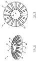
- FIGS. 1, 5 and 6 relate to the present invention, they concern a prefilter (2) comprising a filter unit (4) mounted vertically in a filter housing (6).
- the filter housing (6) has an inlet (8) in a bottom portion (10) thereof for receiving an inflow of liquid to be filtered and an outlet (12) in a top portion (14) thereof for discharging an outflow of filtered liquid.
- the filter unit (4) for each of these preferred embodiments has the following common characteristics. It comprises superposed and spaced-apart inclined lamellar structures (16) each having a lower end side (18) opposite an upper end side (20). As can be appreciated, a passage (22) for a flow of liquid is defined between each two of the lamellar structures (16). Each passage (22) has an inlet (24) for receiving an inflow of liquid to be filtered and an outlet (26) for discharging an outflow of filtered liquid.
- the filter unit (4) further comprises filtering means in each of the passages (22) for obstructing the flow of liquid and retaining particulate matter contained in the liquid.
- the filtering means is preferably an overflow dam wall (28), as best shown in either figures 2 or 8.
- the prefilter (2) also comprises a reception chamber (30) in the filter housing (6) in fluid communication with the inlet (8) of the housing (6) and with the inlets (24) of the filter unit (4).
- the liquid to be filtered enters the housing (6) via the inlet (8) thereof and is flowing across the reception chamber (30) to enter the inlets of the filter unit (24).
- the prefilter (2) further comprises a discharge chamber (32) in the filter housing (4) in fluid communication with the outlets (26) of the filter unit (4) and the outlet (12) of the filter housing (6). Therefore, the filtered liquid discharged at the outlets (26) of the filter unit (4) is flowing across the discharge chamber (32) towards the outlet (12) of the filter housing (6).
- prefilters (2) may advantageously be used at the outlet of a septic tank in order to limit the charge of particulate matters to treat at the purifying element following the septic tank.
- a prefilter (2) according to the invention may also be suitable for use with any tank having an outlet for discharging a liquid containing particulate matters.
- all the lamellar structures (16) are similar and have the shape of hollow truncated cones, as best shown in figures 2 and 8.
- this configuration of the lamellar structures (16) makes it easier to stack the same on top of each other.
- lamellar structures (16) of the filter unit are not limited to that conical configuration. They could have the shape of inclined discs or any other shape as long as they have an inclined surface once superposed with other like lamellar structures.
- the inlet (24) of each of the passages (22) is located on the lower end side (18) of the respective lamellar structures (16) and the outlet (26) is located on the upper end side (20) of the respective lamellar structures (16), whereby the flow of liquid in the passages (22) is ascendant and the particulate matters retained by the dam walls (28) accumulate on the lower side of the lamellar structures (16).
- the particulate matters accumulated behind the dam walls (28) of each lamellar structure (16) to detach from the same and to fall down by gravity into the reception chamber (30). It also allows an easy cleaning of the structure with a jet of water.
- the water enters the filter housing (6) preferably via an inlet structure (34) extending at the bottom end of the filter housing (6), which inlet structure (34) will be described hereinafter.
- the water flows vertically in the reception chamber (30) which is either a cylindrical zone at the centre of the filter unit (4), as in the first preferred embodiment shown in figure 1, or a peripheral zone, as in the second and third preferred embodiments shown in figures 5 and 6.
- the reception chamber (30) is either a cylindrical zone at the centre of the filter unit (4), as in the first preferred embodiment shown in figure 1, or a peripheral zone, as in the second and third preferred embodiments shown in figures 5 and 6.
- the reception chamber (30) is formed by the superposition of the lamellar structures (16), preferably having the shape of a hollow truncated cone.
- the stacked lamellar structures (16) form a series of channels or passages (22) inclined with respect to the horizontal where the water circulates following an ascending radial trajectory, from the centre towards the perimeter or from the perimeter towards the centre.
- the inlet structure (34) extending at the bottom end of the filter housing (6) is in fluid communication with the reception chamber (30) of the filter housing (6) via an outlet (36) of the inlet chamber (34) hermetically connected to the inlet (8) of the filter housing (6).
- the inlet chamber (34) has a sidewall (38) provided with a plurality of slots (40) sized and shaped for receiving and prefiltering liquid to be filtered, whereby the liquid to be filtered enters the inlet chamber (34) via the slots (40) thereof and then flows across the inlet chamber (34) and upwardly in the reception chamber (30) of the filter housing (6).
- the inlet chamber (34) which preferably has a nozzle shape, limits the carry over of fine particles associated with gas bubbles and ensures a better control of the velocity of the liquids entering the filter housing (6). More specifically, it can ensure a velocity of liquids inferior to 0.6 cm/s in order to limit the carry over of the heavier solids.
- the outlet (36) of the inlet structure (34) can be designed so as to be screwable to the inlet (8) of the filter housing (6) or it could also be integrally formed with the filter housing.
- the conical lamellar structures (16) forming the filter unit (4) are disposed such that their outer peripheral edge corresponds to the lower end side (18) of the lamellar structure (16) and that the inner edge corresponds to the upper end side (20), whereby the reception chamber (30) of the prefilter (2) is located all around the filter unit (4) and the discharge chamber (32) is located in a central zone of the filter unit (4).
- the filter housing (6) for both embodiments comprises an annular restriction (66) separating the bottom and top portions (10,14).
- the filter unit (4) is located in the bottom portion (10) of the filter housing (6) and the discharge chamber (32) is in fluid communication with the outlet (12) of the filter housing (6) via an outlet chamber (68) located in the top portion (14) of the filter housing (6).
- the prefilter (2) further comprises an annular watertight liner (70) mounted on an inside rim (72) formed by the restriction (66). The liner (70) is used to hermetically seal the joint between the outlet chamber (68) and the reception chamber (30) of the filter housing (6).
- the invention comprises an upper filter unit (5) located in the top portion (14) of the housing (6) on top of the filter unit (4) previously described and hereinafter referred to as the lower filter unit (4).
- the upper filter unit (5) is used for further filtering liquid previously filtered in the lower filter unit (4).
- the upper filter unit (5) comprises superposed and spaced-apart truncated hollow cones (16) similar in shape and size with the truncated cones (16) of the lower filter unit (4) and being in registry with the same.
- the upper filter unit (5) has a lowermost truncated cone superposed on an uppermost truncated cone of the lower filter unit (4).
- the upper filter unit (5) has a centrally located zone (82) on top of the centrally located zone of the lower filter unit (4).
- a passage (22) for a flow of liquid is formed between each two of the spaced-apart truncated cones (16) of the upper filter unit (5).
- Each of the . passages (22) has an inlet (24) at the upper end side (20) of the conical lamellar structure (16) for receiving an inflow of liquid to be filtered and an outlet (26) at the lower end side (18) thereof for discharging an outflow of filtered liquid, whereby the water flowing in the upper filter unit (5) follows a descending path.
- a filtering means is provided in each of the passages (22) for obstructing the flow of liquid and retaining particulate matter contained in the liquid.
- the filtering means in each passage is an overflow dam wall as described above.
- the hollow truncated cone of the upper filter unit may be set with the inner edge of the cone as the lower end side of the control lamellar structure.
- Each of the passages would then have its inlet at the lower end side of the lamellar structure, whereby the water flowing in the upper filter unit would follow an ascending path.
- the prefilter (2) according to the invention further comprises a reception chamber (84) for the upper filter unit (5) located in the centrally located zone (82) thereof.
- the reception chamber (84) of the upper filter unit (5) is in fluid communication with the discharge chamber (32) of the lower filter unit (4) and with the inlet (24) of each of the passages (22) of the upper filter unit (5).
- a discharge chamber (86) is also provided for the upper filter unit (5). It is located in the top portion (14) of the filter housing (6) all around the upper filter unit (5) and it is in fluid communication with the outlet (26) of each of the passages (22) between the spaced-apart truncated cones (16) and with the outlet (12) of the housing (6).
- An annular watertight liner (70) is provided on the inside rim (72) of the housing (6) formed by the restriction (66) for hermetically separating the reception chamber (30) of the lower filter unit (4) and the discharge chamber (86) of the upper filter unit (5).
- FIG. 8 a preferred version of a hollow truncated cone (16) that can be used with the second and third preferred embodiments is illustrated.
- it comprises an overflow dam wall (28) extending upright from an upper surface thereof.
- the top edge (29) of the dam wall (28) has a corrugated relief and a plurality of vertical slots (88) are provided along the wall (28).
- the inclined configuration of the lamellar structure allows to increase the length of the linear filtration interstice formed with the dam wall and thus greatly increases the filtration capacity of the filter unit in comparison to a flat structure, such as it is described in the American patents nos. 2,900,084; 3,332,552; 4,710,295; 5,582,716 and 5,593,584.
- the addition of vertical slits, perpendicular to the plane of the conical elements allows to increase the total interstitial surface available for filtration.
- a prefilter according to the invention of the hollow conical truncated type, as illustrated in figure 3, with a circular section of 20 cm in diameter, presents an interstitial surface comparable to what is observed with prefilters of horizontal planar structures of 30 cm presently on the market (1080 cm 2 for the 20 cm truncated cone type vs 958 cm 2 for the 30 cm).
- a prefilter according to the present invention as illustrated in figure 5, with a circular section of 18,75 cm in diameter, presents an interstitial surface comparable to that observed with prefilters with planar horizontal structures of 30 cm currently on the market (645 cm 2 of useful surface for the 18,75 cm truncated type cone vs 700 cm 2 for the 30 cm).
- the detachment of the particles and the biological film accumulated allows to reduce the number of cleanings and facilitates them.
- the detachment of the accumulated material is accentuated by the natural wiping and dripping phenomenon resulting from the removal of the filtering structure from the water.
- the inclined configuration of the lamellar structure also eases the cleaning operation of the filter unit with a jet of water.
- each element can either be towards the interior or towards the exterior, depending on the chosen direction of the flow (from the centre to the perimeter or from the perimeter to the centre).
Landscapes
- Chemical & Material Sciences (AREA)
- Chemical Kinetics & Catalysis (AREA)
- Filtration Of Liquid (AREA)
- Centrifugal Separators (AREA)
- Separation Using Semi-Permeable Membranes (AREA)
- Biological Treatment Of Waste Water (AREA)
- Cyclones (AREA)
Claims (15)
- Un pré-filtre comprenant :un boítier de filtration ayant une entrée dans une portion inférieure du boítier pour recevoir un débit entrant de liquide à être filtré et une sortie dans une portion supérieure du boítier pour évacuer un débit sortant de liquide filtré ;une unité de filtration inférieure localisée dans la portion inférieure dudit boítier, comprenant :des structures lamellaires, superposées et espacées l'une de l'autre, ayant la forme de structures creuses tronquées, chacune ayant un côté inférieur opposé à un côté supérieur ;un passage pour un écoulement de liquide entre chacune de deux desdites structures lamellaires, chaque passage ayant une entrée pour recevoir un débit entrant de liquide à être filtré et une sortie pour évacuer un débit sortant d'un liquide filtré ;des moyens de filtration dans chacun desdits passages pour obstruer l'écoulement de liquide et retenir des matières particulaires contenues dans le liquide ; etune chambre d'évacuation en communication fluide avec les sorties de l'unité de filtration inférieure, la chambre d'évacuation étant localisée dans une zone centrale de l'unité de filtration inférieure ;une chambre de réception dans le boítier en communication fluide avec l'entrée dudit boítier et avec les entrées de l'unité de filtration inférieure; le liquide à être filtré entrant dans le boítier via l'entrée du boítier et s'écoulant à travers la chambre de réception pour pénétrer les entrées de l'unité de filtration inférieure; et le liquide filtré sortant des sorties de l'unité de filtration inférieure et s'écoulant à travers la chambre d'évacuation vers la sortie du boítier ;une unité de filtration supérieure localisée dans la partie supérieure du boítier au-dessus de l'unité de filtration inférieure, pour filtrer davantage le liquide précédemment filtré dans l'unité de filtration inférieure, l'unité de filtration supérieure comprenant:des structures creuses tronquées, superposées et espacées similaires en forme et en dimension aux structures tronquées de l'unité de filtration inférieure disposées directement au-dessus de celles-ci, l'unité de filtration supérieure ayant une structure tronquée de bas superposée à une structure tronquée de haut de l'unité de filtration inférieure, les structures creuses tronquées de l'unité de filtration supérieure ayant un côté supérieur et un côté inférieur, et une zone centrale localisée au-dessus de la zone centrale de l'unité de filtration inférieure;un passage pour un écoulement de liquide entre chacune de deux desdites structures tronquées et espacées, ayant une entrée pour recevoir un débit entrant de liquide à être filtré et une sortie pour évacuer un débit sortant de liquide filtré; etdes moyens de filtration dans chacun desdits passages pour obstruer l'écoulement de liquide et retenir des matières particulaires contenues dans le liquide;une chambre de réception localisée dans ladite zone centrale, la chambre de réception étant en communication fluide avec la chambre d'évacuation de l'unité de filtration inférieure et avec l'entrée de chacun des passages de l'unité de filtration supérieure;une chambre d'évacuation pour l'unité de filtration supérieure localisée dans la partie supérieure du boítier autour de ladite unité de filtration supérieure, la chambre d'évacuation étant en communication fluide avec la sortie de chaque passage de l'unité de filtration supérieure et avec la sortie du boítier ;des moyens pour séparer hermétiquement la chambre de réception de l'unité de filtration inférieure et la chambre d'évacuation de l'unité de filtration supérieure ; etdes moyens de montage pour monter les unités de filtration verticalement dans le boítier.
- Un pré-filtre selon la revendication 1, dans lequel l'entrée de chacun desdits passages de l'unité de filtration inférieure est localisée sur le côté inférieur de la structure lamellaire respective et la sortie est localisée sur le côté supérieur de la structure lamellaire respective, de sorte que l'écoulement de liquide dans les passages est ascendant dans l'unité de filtration inférieure.
- Un pré-filtre selon la revendication 2, dans lequel chacune desdites structures lamellaires en forme de structures creuses tronquées a une arête périphérique extérieure et une arête intérieure plus petite que l'arête périphérique extérieure, l'arête périphérique extérieure étant sur le côté inférieur de la structure lamellaire et l'arête intérieure étant sur le côté supérieur de la structure lamellaire, le liquide entrant ainsi dans le passage entre deux desdites structures tronquées dans l'unité de filtration inférieure depuis l'arête périphérique extérieure et s'écoulant en ascension vers l'arête intérieure.
- Un pré-filtre selon l'une quelconque des revendications 1 à 3, dans lequel chacune desdites deux structures lamellaires des unités de filtration inférieure et supérieure inclut une structure lamellaire supérieure, une structure lamellaire inférieure, et les moyens de filtration dans chacun desdits passages comprennent :un barrage de débordement s'étendant en hauteur depuis ladite structure lamellaire inférieure et ayant un bord supérieur espacé d'une sous-face de la structure lamellaire supérieure ; etun interstice linéaire entre le bord supérieur du barrage de débordement et la sous-face du bas de la structure lamellaire supérieure.
- Un pré-filtre selon la revendication 4, dans lequel le barrage de débordement de chacun desdits passages suit un tracé sinueux.
- Un pré-filtre selon la revendication 5, dans lequel le barrage continu dans chacun desdits passages a un bord supérieur avec un relief ondulé.
- Un pré-filtre selon la revendication 4, dans lequel le barrage de débordement dans chacun desdits passages comprend une pluralité de fentes verticales pour filtrer davantage les liquides.
- Un pré-filtre selon la revendication 3, comprenant des moyens de jonction pour joindre les structures lamellaires les unes aux autres en superposition.
- Un pré-filtre selon la revendication 8, dans lequel les moyens de jonction comprennent :une pluralité de languettes s'étendant verticalement depuis l'arête intérieure de chacune des structures tronquées ; etune pluralité d'éléments d'appui de languette dans l'arête intérieure de la structure tronquée, chaque élément d'appui de languettes étant moulé pour s'interconnecter avec une languette d'un autre cône tronqué.
- Un bloc de filtre selon la revendication 9, dans lequel chacune desdites languettes a un bout en forme de crochet et chaque élément d'appui de languettes a la forme d'une rainure verticale dans laquelle une languette d'une autre structure tronquée est insérable par glissement.
- Un pré-filtre selon la revendication 1, dans lequel ladite structure creuse tronquée est un cône creux tronqué.
- Un pré-filtre selon la revendication 1, dans lequel le boítier a une extrémité supérieure et une extrémité inférieure, l'entrée du boítier étant une ouverture dans l'extrémité inférieure, la combinaison comprenant :une chambre d'admission s'étendant dans l'extrémité inférieure du boítier, la chambre d'admission étant en communication fluide avec la chambre de réception du boítier via une sortie de la chambre d'admission connectée hermétiquement à l'entrée du boítier, la chambre d'admission ayant une paroi munie d'une pluralité de fentes de dimensions et de forme prévues pour recevoir et pré-filtrer du liquide à filtrer, le liquide à filtrer entrant ainsi dans la chambre d'admission via lesdites fentes et s'écoulant à travers la chambre d'admission puis en ascension dans la chambre de réception du boítier.
- Un pré-filtre selon l'une quelconque des revendications 1 à 12, comprenant un couvercle adapté pour s'ajuster hermétiquement sur l'extrémité supérieure du boítier.
- Un pré-filtre selon la revendication 13, dans lequel les moyens de montage comprennent:un dispositif de suspension disposé dans le couvercle, le dispositif de suspension ayant une partie inférieure s'étendant vers le bas dans le boítier ; etdes supports localisés à ladite partie inférieure pouvant se connecter à un cône tronqué supérieur pour suspendre les unités de filtration supérieure et inférieure dans le boítier.
- Un pré-filtre selon la revendication 14, dans lequel le moyen pour séparer hermétiquement la chambre de réception de l'unité de filtration inférieure et la chambre d'évacuation de l'unité de filtration supérieure comprend :une restriction dans la paroi du boítier séparant la partie inférieure de la partie supérieure ;etun recouvrement étanche monté à ladite restriction.
Applications Claiming Priority (3)
| Application Number | Priority Date | Filing Date | Title |
|---|---|---|---|
| CA2301992 | 2000-03-23 | ||
| CA002301992A CA2301992A1 (fr) | 2000-03-23 | 2000-03-23 | Pre-filtre pour fosse septique |
| PCT/CA2001/000385 WO2001070370A1 (fr) | 2000-03-23 | 2001-03-22 | Dispositif de filtrage a structures lamellaires servant a filtrer des liquides |
Publications (2)
| Publication Number | Publication Date |
|---|---|
| EP1265686A1 EP1265686A1 (fr) | 2002-12-18 |
| EP1265686B1 true EP1265686B1 (fr) | 2004-05-26 |
Family
ID=4165617
Family Applications (1)
| Application Number | Title | Priority Date | Filing Date |
|---|---|---|---|
| EP01916800A Expired - Lifetime EP1265686B1 (fr) | 2000-03-23 | 2001-03-22 | Dispositif de filtrage a structures lamellaires servant a filtrer des liquides |
Country Status (7)
| Country | Link |
|---|---|
| US (1) | US6942796B2 (fr) |
| EP (1) | EP1265686B1 (fr) |
| AT (1) | ATE267636T1 (fr) |
| AU (1) | AU2001243995A1 (fr) |
| CA (1) | CA2301992A1 (fr) |
| DE (1) | DE60103513D1 (fr) |
| WO (1) | WO2001070370A1 (fr) |
Families Citing this family (17)
| Publication number | Priority date | Publication date | Assignee | Title |
|---|---|---|---|---|
| US6814863B2 (en) | 2002-07-26 | 2004-11-09 | Dennis F. Hallahan | Radial flow septic tank |
| US7210585B2 (en) * | 2002-12-09 | 2007-05-01 | Caterpillar Inc | Edge filter assembly |
| FR2862632B1 (fr) * | 2003-11-25 | 2006-04-14 | Simop | Cuve de pretraitement des eaux usees equipee d'un dispositif de prefiltration ainsi que dispositif de prefiltration destine a une telle cuve |
| ITTO20040557A1 (it) * | 2004-08-06 | 2004-11-06 | Buscemi S N C Di Buscemi Lucia | Elemento filtrante e filtro comprendente una pluralita' di elementi filtranti impilati assialmente |
| US7740756B2 (en) * | 2005-10-04 | 2010-06-22 | Peter W. Gavin | Wastewater filter system |
| US8226833B1 (en) | 2007-04-25 | 2012-07-24 | Theophilus B. Terry, III | Multi-level filter device |
| US8333894B1 (en) | 2007-04-25 | 2012-12-18 | Theophilus B. Terry, III | Multi-level filter device |
| US7682512B2 (en) * | 2007-04-25 | 2010-03-23 | Theophilus B. Terry, III | Multi-level filter device |
| ES2426068T3 (es) * | 2008-09-25 | 2013-10-21 | Nestec S.A. | Cartucho de filtro para una máquina de bebidas y una máquina de bebidas con un cartucho de filtro |
| US8182676B2 (en) | 2009-08-07 | 2012-05-22 | Bear Onsite, Llc | Wastewater effluent filter case with gas baffle |
| US8342338B2 (en) * | 2010-03-22 | 2013-01-01 | Hydro International Plc | Separator for separating solids from an influent |
| SE535177C2 (sv) * | 2010-04-14 | 2012-05-08 | Nanospace Ab | Mikromekaniska filter |
| KR101014159B1 (ko) * | 2010-04-19 | 2011-02-14 | 케이원에코텍 주식회사 | 원형 여과판 및 이 여과판이 구성된 여과장치 |
| PL2675541T3 (pl) | 2011-02-17 | 2023-07-17 | Flamco B.V. | Ulepszone urządzenie usuwające mikropęcherzyki i cząstki zanieczyszczeń |
| CA3008149C (fr) * | 2018-06-27 | 2020-05-05 | Aly Gomaa | Systeme de recuperation de residus |
| US20240091680A1 (en) * | 2019-09-30 | 2024-03-21 | Orenco Systems, Inc. | Passive self-cleaning filtration method and apparatus |
| CN112138451B (zh) * | 2020-09-28 | 2022-05-24 | 迈邦(北京)环保工程有限公司 | 一种可快速处理污水堵塞的过滤装置 |
Family Cites Families (26)
| Publication number | Priority date | Publication date | Assignee | Title |
|---|---|---|---|---|
| NL30162C (fr) * | ||||
| US653012A (en) * | 1899-12-20 | 1900-07-03 | Charles Herschel Koyl | Apparatus for purifying water. |
| US2670851A (en) * | 1949-06-07 | 1954-03-02 | Hawley Products Co | Disposable liquid filter element |
| US2750045A (en) * | 1953-01-26 | 1956-06-12 | Melville C Hoffmann | Filter |
| US2900084A (en) | 1956-07-18 | 1959-08-18 | Robert L Zabel | Outlet trap for septic tanks |
| US3332552A (en) | 1963-09-27 | 1967-07-25 | Robert L Zabel | Sewage disposal septic tanks |
| US3515280A (en) * | 1968-12-03 | 1970-06-02 | Watson H Parker | Stacked element filter apparatus |
| JPS5623647B1 (fr) * | 1971-05-25 | 1981-06-01 | ||
| CH563180A5 (fr) * | 1973-09-13 | 1975-06-30 | Escher Wyss Ag | |
| US3951818A (en) * | 1974-12-09 | 1976-04-20 | Milovan Bosnjak | Chevron clarifier |
| GB2039766A (en) * | 1978-12-19 | 1980-08-20 | Fram Europ | Corrugated plate oil/water separator |
| DE3031412C2 (de) * | 1980-08-20 | 1985-02-14 | Reinhart von Dr.-Ing. 8011 Solalinden Nordenskjöld | Vorrichtung zum Nachklären von Abwasser |
| US4439323A (en) | 1981-07-02 | 1984-03-27 | Orenco Systems, Inc. | Method of discharging septic tank filtered effluent |
| US4402829A (en) * | 1982-01-04 | 1983-09-06 | R & G Sloane Manufacturing Company, Inc. | Disc-type filter |
| US4707259A (en) * | 1984-03-29 | 1987-11-17 | Charles Doucet | Filter with superposed rings for filtering liquids |
| US4710295A (en) | 1984-08-09 | 1987-12-01 | Robert Zabel | Septic tank filters |
| EP0233953A1 (fr) * | 1985-12-20 | 1987-09-02 | Mordeki Drori | Filtres à anneaux superposés |
| AU640258B2 (en) * | 1991-08-16 | 1993-08-19 | Kotobuki Techrex Ltd. | Sedimentation centrifuge |
| US5382357A (en) | 1993-11-01 | 1995-01-17 | Nurse; Harry L. | Septic tank outlet filter |
| US5492635A (en) | 1994-12-09 | 1996-02-20 | Orenco Systems, Inc. | Septic tank effluent filtering method |
| US5593584A (en) | 1995-05-08 | 1997-01-14 | Nurse, Jr.; Harry L. | Septic tank filter |
| US5582716A (en) * | 1995-05-08 | 1996-12-10 | Nurse, Jr.; Harry L. | Filter for septic tanks |
| US5580453A (en) | 1995-08-11 | 1996-12-03 | Nurse, Jr.; Harry L. | Filter apparatus for waste water discharge system |
| US5683577A (en) | 1996-05-22 | 1997-11-04 | Nurse, Jr.; Harry L. | Filter device for wastewater treatment system |
| US6360898B1 (en) * | 2000-04-06 | 2002-03-26 | Harry L. Nurse, Jr. | Filtration device for a waste water treatment system |
| US6306299B1 (en) * | 2000-04-06 | 2001-10-23 | Harry L. Nurse, Jr. | Filtration device for a waste water treatment system |
-
2000
- 2000-03-23 CA CA002301992A patent/CA2301992A1/fr not_active Abandoned
-
2001
- 2001-03-22 AT AT01916800T patent/ATE267636T1/de not_active IP Right Cessation
- 2001-03-22 DE DE60103513T patent/DE60103513D1/de not_active Expired - Lifetime
- 2001-03-22 AU AU2001243995A patent/AU2001243995A1/en not_active Abandoned
- 2001-03-22 EP EP01916800A patent/EP1265686B1/fr not_active Expired - Lifetime
- 2001-03-22 WO PCT/CA2001/000385 patent/WO2001070370A1/fr not_active Ceased
- 2001-03-23 US US09/815,857 patent/US6942796B2/en not_active Expired - Fee Related
Also Published As
| Publication number | Publication date |
|---|---|
| DE60103513D1 (de) | 2004-07-01 |
| US6942796B2 (en) | 2005-09-13 |
| EP1265686A1 (fr) | 2002-12-18 |
| ATE267636T1 (de) | 2004-06-15 |
| US20010023845A1 (en) | 2001-09-27 |
| WO2001070370A1 (fr) | 2001-09-27 |
| AU2001243995A1 (en) | 2001-10-03 |
| CA2301992A1 (fr) | 2001-09-23 |
Similar Documents
| Publication | Publication Date | Title |
|---|---|---|
| EP1265686B1 (fr) | Dispositif de filtrage a structures lamellaires servant a filtrer des liquides | |
| US5762790A (en) | Septic tank filtering system | |
| US12440789B2 (en) | Rectangular filters, assembly and method for filtration | |
| AU2007231896B2 (en) | A droplet separator | |
| US5580453A (en) | Filter apparatus for waste water discharge system | |
| US5582716A (en) | Filter for septic tanks | |
| US5122287A (en) | Filtration system | |
| US7740756B2 (en) | Wastewater filter system | |
| US6136190A (en) | Septic tank filtering system | |
| US6360898B1 (en) | Filtration device for a waste water treatment system | |
| US5762793A (en) | Filter apparatus for waste water discharge system | |
| US5770081A (en) | Apparatus for and method of reducing solids and controlling surges in the flow of effluent from a wastewater treatment plant | |
| US6306299B1 (en) | Filtration device for a waste water treatment system | |
| US6015488A (en) | Filter system for septic tank | |
| CN112704942B (zh) | 分离器 | |
| US4533475A (en) | Method and apparatus for fluid filtration including particle precipitation | |
| CA2407527C (fr) | Dispositif de filtrage a structures lamellaires servant a filtrer des liquides | |
| US5779896A (en) | Gas baffle for a waste water treatment plant effluent | |
| US5900149A (en) | Sedimenter | |
| US20190060788A1 (en) | Wedge shaped filters, assembly and method for filtration and coalescing | |
| KR102367543B1 (ko) | 유공블록형 하부집수장치가 적용된 여과지 | |
| US20020139758A1 (en) | Method and apparatus for removing particulate contaminants from commercial laundry waste water | |
| US20050000877A1 (en) | Method and apparatus for removing particulate contaminants from commercial laundry waste water | |
| WO2008002057A1 (fr) | Appareil de purification d'eau utilisant des cyclones | |
| US4490255A (en) | Combined settling and liquid storage tank |
Legal Events
| Date | Code | Title | Description |
|---|---|---|---|
| PUAI | Public reference made under article 153(3) epc to a published international application that has entered the european phase |
Free format text: ORIGINAL CODE: 0009012 |
|
| 17P | Request for examination filed |
Effective date: 20020817 |
|
| AK | Designated contracting states |
Kind code of ref document: A1 Designated state(s): AT BE CH CY DE DK ES FI FR GB GR IE IT LI LU MC NL PT SE TR |
|
| AX | Request for extension of the european patent |
Free format text: AL;LT;LV;MK;RO;SI |
|
| RIN1 | Information on inventor provided before grant (corrected) |
Inventor name: TALBOT, PIERRE Inventor name: LACASSE, ROGER Inventor name: JUNEAU, BERNARD Inventor name: OUELLET, HENRI |
|
| GRAH | Despatch of communication of intention to grant a patent |
Free format text: ORIGINAL CODE: EPIDOS IGRA |
|
| GRAS | Grant fee paid |
Free format text: ORIGINAL CODE: EPIDOSNIGR3 |
|
| 17Q | First examination report despatched |
Effective date: 20040203 |
|
| GRAA | (expected) grant |
Free format text: ORIGINAL CODE: 0009210 |
|
| AK | Designated contracting states |
Kind code of ref document: B1 Designated state(s): AT BE CH CY DE DK ES FI FR GB GR IE IT LI LU MC NL PT SE TR |
|
| PG25 | Lapsed in a contracting state [announced via postgrant information from national office to epo] |
Ref country code: IT Free format text: LAPSE BECAUSE OF FAILURE TO SUBMIT A TRANSLATION OF THE DESCRIPTION OR TO PAY THE FEE WITHIN THE PRESCRIBED TIME-LIMIT;WARNING: LAPSES OF ITALIAN PATENTS WITH EFFECTIVE DATE BEFORE 2007 MAY HAVE OCCURRED AT ANY TIME BEFORE 2007. THE CORRECT EFFECTIVE DATE MAY BE DIFFERENT FROM THE ONE RECORDED. Effective date: 20040526 Ref country code: BE Free format text: LAPSE BECAUSE OF FAILURE TO SUBMIT A TRANSLATION OF THE DESCRIPTION OR TO PAY THE FEE WITHIN THE PRESCRIBED TIME-LIMIT Effective date: 20040526 Ref country code: LI Free format text: LAPSE BECAUSE OF FAILURE TO SUBMIT A TRANSLATION OF THE DESCRIPTION OR TO PAY THE FEE WITHIN THE PRESCRIBED TIME-LIMIT Effective date: 20040526 Ref country code: TR Free format text: LAPSE BECAUSE OF FAILURE TO SUBMIT A TRANSLATION OF THE DESCRIPTION OR TO PAY THE FEE WITHIN THE PRESCRIBED TIME-LIMIT Effective date: 20040526 Ref country code: NL Free format text: LAPSE BECAUSE OF FAILURE TO SUBMIT A TRANSLATION OF THE DESCRIPTION OR TO PAY THE FEE WITHIN THE PRESCRIBED TIME-LIMIT Effective date: 20040526 Ref country code: AT Free format text: LAPSE BECAUSE OF FAILURE TO SUBMIT A TRANSLATION OF THE DESCRIPTION OR TO PAY THE FEE WITHIN THE PRESCRIBED TIME-LIMIT Effective date: 20040526 Ref country code: CH Free format text: LAPSE BECAUSE OF FAILURE TO SUBMIT A TRANSLATION OF THE DESCRIPTION OR TO PAY THE FEE WITHIN THE PRESCRIBED TIME-LIMIT Effective date: 20040526 Ref country code: FI Free format text: LAPSE BECAUSE OF FAILURE TO SUBMIT A TRANSLATION OF THE DESCRIPTION OR TO PAY THE FEE WITHIN THE PRESCRIBED TIME-LIMIT Effective date: 20040526 |
|
| REG | Reference to a national code |
Ref country code: GB Ref legal event code: FG4D |
|
| REG | Reference to a national code |
Ref country code: CH Ref legal event code: EP |
|
| REG | Reference to a national code |
Ref country code: IE Ref legal event code: FG4D |
|
| REF | Corresponds to: |
Ref document number: 60103513 Country of ref document: DE Date of ref document: 20040701 Kind code of ref document: P |
|
| PG25 | Lapsed in a contracting state [announced via postgrant information from national office to epo] |
Ref country code: DK Free format text: LAPSE BECAUSE OF FAILURE TO SUBMIT A TRANSLATION OF THE DESCRIPTION OR TO PAY THE FEE WITHIN THE PRESCRIBED TIME-LIMIT Effective date: 20040826 Ref country code: GR Free format text: LAPSE BECAUSE OF FAILURE TO SUBMIT A TRANSLATION OF THE DESCRIPTION OR TO PAY THE FEE WITHIN THE PRESCRIBED TIME-LIMIT Effective date: 20040826 Ref country code: SE Free format text: LAPSE BECAUSE OF FAILURE TO SUBMIT A TRANSLATION OF THE DESCRIPTION OR TO PAY THE FEE WITHIN THE PRESCRIBED TIME-LIMIT Effective date: 20040826 |
|
| PG25 | Lapsed in a contracting state [announced via postgrant information from national office to epo] |
Ref country code: DE Free format text: LAPSE BECAUSE OF FAILURE TO SUBMIT A TRANSLATION OF THE DESCRIPTION OR TO PAY THE FEE WITHIN THE PRESCRIBED TIME-LIMIT Effective date: 20040827 |
|
| PG25 | Lapsed in a contracting state [announced via postgrant information from national office to epo] |
Ref country code: ES Free format text: LAPSE BECAUSE OF FAILURE TO SUBMIT A TRANSLATION OF THE DESCRIPTION OR TO PAY THE FEE WITHIN THE PRESCRIBED TIME-LIMIT Effective date: 20040906 |
|
| LTIE | Lt: invalidation of european patent or patent extension |
Effective date: 20040526 |
|
| REG | Reference to a national code |
Ref country code: CH Ref legal event code: PL |
|
| NLV1 | Nl: lapsed or annulled due to failure to fulfill the requirements of art. 29p and 29m of the patents act | ||
| ET | Fr: translation filed | ||
| PG25 | Lapsed in a contracting state [announced via postgrant information from national office to epo] |
Ref country code: GB Free format text: LAPSE BECAUSE OF NON-PAYMENT OF DUE FEES Effective date: 20050322 Ref country code: IE Free format text: LAPSE BECAUSE OF NON-PAYMENT OF DUE FEES Effective date: 20050322 Ref country code: CY Free format text: LAPSE BECAUSE OF FAILURE TO SUBMIT A TRANSLATION OF THE DESCRIPTION OR TO PAY THE FEE WITHIN THE PRESCRIBED TIME-LIMIT Effective date: 20050322 Ref country code: LU Free format text: LAPSE BECAUSE OF NON-PAYMENT OF DUE FEES Effective date: 20050322 |
|
| PG25 | Lapsed in a contracting state [announced via postgrant information from national office to epo] |
Ref country code: MC Free format text: LAPSE BECAUSE OF NON-PAYMENT OF DUE FEES Effective date: 20050331 |
|
| PLBE | No opposition filed within time limit |
Free format text: ORIGINAL CODE: 0009261 |
|
| STAA | Information on the status of an ep patent application or granted ep patent |
Free format text: STATUS: NO OPPOSITION FILED WITHIN TIME LIMIT |
|
| 26N | No opposition filed |
Effective date: 20050301 |
|
| GBPC | Gb: european patent ceased through non-payment of renewal fee |
Effective date: 20050322 |
|
| REG | Reference to a national code |
Ref country code: IE Ref legal event code: MM4A |
|
| PG25 | Lapsed in a contracting state [announced via postgrant information from national office to epo] |
Ref country code: PT Free format text: LAPSE BECAUSE OF NON-PAYMENT OF DUE FEES Effective date: 20041026 |
|
| PGFP | Annual fee paid to national office [announced via postgrant information from national office to epo] |
Ref country code: FR Payment date: 20110421 Year of fee payment: 11 |
|
| REG | Reference to a national code |
Ref country code: FR Ref legal event code: ST Effective date: 20121130 |
|
| PG25 | Lapsed in a contracting state [announced via postgrant information from national office to epo] |
Ref country code: FR Free format text: LAPSE BECAUSE OF NON-PAYMENT OF DUE FEES Effective date: 20120402 |